
Power FC PFC Boost Kit Harness question

Thread Starter
Joined: Mar 2001
Posts: 1,124
Likes: 0
From: Woodbine, MD
I picked up a boost control kit from FortyOunce, replaced the stock sensor and was about to plug the stock sensor into the PFC when I realized that my adapter harness has a 3 wire plug but the jack on the PFC has 5 wires.
Does everyone have the 3 wire harness? If you had a 5 wire connector, which pins were used? If not, how did you connect it?
Much appreciated.
Does everyone have the 3 wire harness? If you had a 5 wire connector, which pins were used? If not, how did you connect it?
Much appreciated.
Thread Starter
Joined: Mar 2001
Posts: 1,124
Likes: 0
From: Woodbine, MD
Well Paul, that's the problem. It doesn't match up. The adapter harness has an end that plugs into the map sensor and another end with a 3-pin connector. My PFC has a 5 pin connector. 3 <> 5. That's my confusion.
So I wonder if kt this was made for a different PFC with a 3 pin plug, and what the pinout might be.
If it didn't rain last night I'd go and snap a pic to illustrate my situation.
So I wonder if kt this was made for a different PFC with a 3 pin plug, and what the pinout might be.
If it didn't rain last night I'd go and snap a pic to illustrate my situation.
Thread Starter
Joined: Mar 2001
Posts: 1,124
Likes: 0
From: Woodbine, MD
Here's a pic of what I'm talking about. The socket at the PFC is 5 pins, but the PFC end of the harness is only 3 pins.
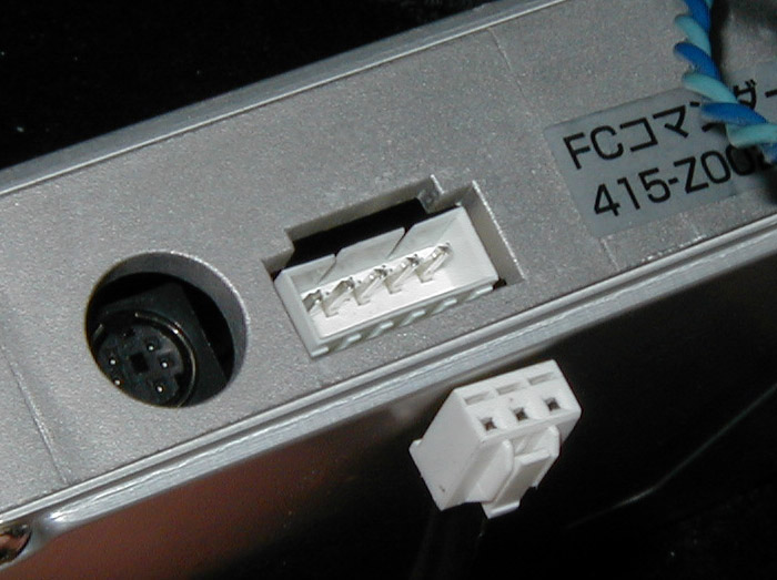
There was an old pic Spyfish007 took a while ago that seems to show a 5 pin plug on the harness.

So it looks like I have a harness, perhaps for a different PFC? In any event, if someone with the boost kit wouldn't mind helping me get the correct pinout so that I could correctly wire this sucker up, I would be most appreciative. Sorry my explanation wasn't clear before.
Thanks,
..Dave
There was an old pic Spyfish007 took a while ago that seems to show a 5 pin plug on the harness.
So it looks like I have a harness, perhaps for a different PFC? In any event, if someone with the boost kit wouldn't mind helping me get the correct pinout so that I could correctly wire this sucker up, I would be most appreciative. Sorry my explanation wasn't clear before.
Thanks,
..Dave
Thread Starter
Joined: Mar 2001
Posts: 1,124
Likes: 0
From: Woodbine, MD
I bought it third-hand. I doubt they'll do much for me but tell me to return it fro where I bought it... anyway I really don't mind making a new end for the harness, I just need a willing participant to snap a pic of their 5 pin plug.
Guess I'll have to start stalking boost kit users now...
Guess I'll have to start stalking boost kit users now...
Trending Topics

Full Member
Joined: Mar 2001
Posts: 222
Likes: 1
From: Okinawa, Japan
I'm pretty sure it is red/green/black starting closest to the commander plug. I had a five prong plug harness and an older pfc with the 3 prong plug, but it was like 4 yrs ago when I modified it.
Thread Starter
Joined: Mar 2001
Posts: 1,124
Likes: 0
From: Woodbine, MD
Thanks, Igy. I played with it a little today.. I tried it like you suggested, and in different positions. It didn't seem to make a difference. At rest, the PFC reads like -20 mmHg.. which is just as close as my stock sensor read.
I was under the impression (hoping) that by hooking up the stock sensor it would do an altitude correction and compare to ambient air pressure. Oh well, close enough.
I was under the impression (hoping) that by hooking up the stock sensor it would do an altitude correction and compare to ambient air pressure. Oh well, close enough.
Yellow Dragon is no more
Joined: Apr 2001
Posts: 1,687
Likes: 1
From: Knoxville, TN
My adapter harness was 5pin. You can test the PFC for two the pins. Look for GND and 5V. Use a multimeter to test for continunity to GND. Once you locate that, test for 5V. That will leave only 3 pins available for the return signal. Oh course red=+5V, green=signal, & black=GND.
Thread Starter
Joined: Mar 2001
Posts: 1,124
Likes: 0
From: Woodbine, MD
I haven't crawled down there yet. I've been running with the stock map sensor disconnected since the 3-bar doesn't read too far off by itself. It's been inconveniently cold and rainy up here in MD lately, and in a one-car garage I just don't have the room to do it. I'll see if I can get to it on Thursday.. It should be warming up soon. 
I'll report back..
I'll report back..
Thread Starter
Joined: Mar 2001
Posts: 1,124
Likes: 0
From: Woodbine, MD
Well, I played with this a little today. Didn't find what I was expecting so maybe my expectations are incorrect.
I found the ground pin first. Next came the +5v and +12v pins. No problem. Looking at the pic of the 5-pin harness you can make out that all 3 leads are together, so I have to assume that the second pin is actually the map signal. For grins I also tried connecting the signal out to the last pin as well. No dice. I get -35mmHg with it hooked up each way. Incidentally that's what I get when the stock map sensor is completely disconnected.
Perhaps it doesn't factor readings in while the car is not actually running? Perhaps it doesn't do jack ****. I expected that some how I'd get to see 0 mmHg. Oh well, I'll just hook it back up like Igy suggected and pretent to be ignorant. I am suppsed to use Option 1 in the PIM settings, correct?
Thanks for the help guys...
O Commander Plug
- +5v
- ?? map signal
- ground
- +battery volts
- ?? Seems to be some other input?
FYI.. I got a few ohms between the second pin and ground, and a trickle of voltage. No resistance between the 5th and ground, but I did see a little voltage here.
Yellow Dragon is no more
Joined: Apr 2001
Posts: 1,687
Likes: 1
From: Knoxville, TN
Option 1 in PIM is correct.
I don't remember seeing any change on my commander when I was running this setup either. I think that just reports the main MAP sensor. I wouldn't be surprised if this correction factor is applied more internally in the PowerFC. Hooking up the datalogit and running basic boost verses advance boost would be an interesting test-that is with and without the stock sensor connected.
I don't remember seeing any change on my commander when I was running this setup either. I think that just reports the main MAP sensor. I wouldn't be surprised if this correction factor is applied more internally in the PowerFC. Hooking up the datalogit and running basic boost verses advance boost would be an interesting test-that is with and without the stock sensor connected.
Rebreaking things
Joined: Jun 2001
Posts: 2,586
Likes: 0
From: 1 foot in Boston 1 in NJ
Are you running this with the stock twins? I am curious to hear if it effects the way the power comes on. A friend of mine recently started using an aftermarket boost controller instead of the PFC and noticed a huge difference in the rate the power/boost came up.
One thing I've always wondered about is how the apexi kit and the AVC-R can control the stock twins with one solenoid. I assume the stock WG/precontrol solenoids are retained, otherwise I don't see how each turbo could be regulated individually.
One thing I've always wondered about is how the apexi kit and the AVC-R can control the stock twins with one solenoid. I assume the stock WG/precontrol solenoids are retained, otherwise I don't see how each turbo could be regulated individually.
Thread Starter
Joined: Mar 2001
Posts: 1,124
Likes: 0
From: Woodbine, MD
Nope, no more twins. T04S.
I'm not sure how it's supposed to work with the twins though.. The AVC-R docs up on the apex'i site illustrate a couple of ways to hook it up..
I'm not sure how it's supposed to work with the twins though.. The AVC-R docs up on the apex'i site illustrate a couple of ways to hook it up..
Originally posted by CCarlisi
Are you running this with the stock twins? I am curious to hear if it effects the way the power comes on. A friend of mine recently started using an aftermarket boost controller instead of the PFC and noticed a huge difference in the rate the power/boost came up.
One thing I've always wondered about is how the apexi kit and the AVC-R can control the stock twins with one solenoid. I assume the stock WG/precontrol solenoids are retained, otherwise I don't see how each turbo could be regulated individually.
Yellow Dragon is no more
Joined: Apr 2001
Posts: 1,687
Likes: 1
From: Knoxville, TN
On twins it would just run the wastegate like it supposed to do. You change the MAP sensor setting and then leave it alone. You don't have to put the car in non-seq mode to run the boost kit. Let the factory solenoid run the precontrol door.

Thread
Thread Starter
Forum
Replies
Last Post
trickster
2nd Generation Specific (1986-1992)
25
Jul 1, 2023 04:40 PM