
Power FC inovative wideband o2


Originally Posted by HYDOUKEN
- hey rotarypower101 I was curious as to what you are using the other Inputs for.....
- Klaus, what rotarypower101 is trying to accomplish is it possible with the LC-1. Also Matt or Klaus.....with me connecting a ground wire directly to AN2...will that affect anything...besides making a more accurate WB02 reading. Also I was concidering soldering all the wires (White/Green/XD-1 Ground/ground wire to ecu braket) together and then putting it into AN2...would this be a cleaner way of doing it....basically so one wire doesnt fall out of the AN2 by accident
- Klaus, what rotarypower101 is trying to accomplish is it possible with the LC-1. Also Matt or Klaus.....with me connecting a ground wire directly to AN2...will that affect anything...besides making a more accurate WB02 reading. Also I was concidering soldering all the wires (White/Green/XD-1 Ground/ground wire to ecu braket) together and then putting it into AN2...would this be a cleaner way of doing it....basically so one wire doesnt fall out of the AN2 by accident
Originally Posted by Matt Hey
Setup Datalogit menu Setup->Auxiliary with 0V=7.35, 5V=22.39 and Delta AN1-AN2 checked)
Does this part make sense to you?
It is just simple relationship parameters.
Joined: Sep 2004
Posts: 3,258
Likes: 9
From: South Florida
Originally Posted by HYDOUKEN
ok now that I have the stuff almost hooked up....what do I put into the FC Edit program to make it read the LC-1 correctly?
Should be under setup, auxiliary
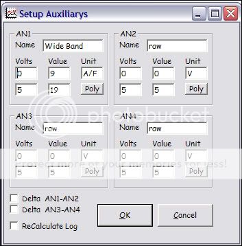
Cant load a pic to show where parameters go, but look at my other pic posted.
Under volts it will be 0 and 5 in the same places, and value will be 7.35 where my 10 is, and 22.39 where my 20 is

Cant load a pic to show where parameters go, but look at my other pic posted.
Under volts it will be 0 and 5 in the same places, and value will be 7.35 where my 10 is, and 22.39 where my 20 is
Joined: Oct 2001
Posts: 414
Likes: 0
From: South Carolina
Thanks rotarypower101 pictures make things look so much easier 
Since I am also hooking up the ground to AN2 ....do I need to change anything there..or just leave it like you have it in the picture, volts at 0 and 5 , value 0 and 0, unit is V
Since I am also hooking up the ground to AN2 ....do I need to change anything there..or just leave it like you have it in the picture, volts at 0 and 5 , value 0 and 0, unit is V
^
I think these would be irrelevant to him as he is using the LC1, and it sounds like the parameters are 7.35 and 22.39, from post by other members and directly from Klaus himself.
The LM1 on the otherhand can be programmed to any parameters you wish within the LM1s operating range whether it be 9-19 or 10-20 like mine, it should all work and is the end users choice for resolution.
Originally Posted by klatinn
On both LC-1 types:
- Red is switched 12V power
- Yellow is Analog out 1, with the default programming simulating a NBO2 sensor. Leave open and insulated if not used
- Brown is Analog out 2. with the default programming it outputs a linear voltage from 7.35 AFR (Lambda 0.5) at 0 Volt to 22.4 AFR (Lambda 1.523) at 5V. Leave open and insulated if not used.

Originally Posted by HYDOUKEN
Yes, thankyou Matt and klatinn for all the input....I got it straight now, but still curious as to why there is two different versions (6 wire and 7 wire LC-1....I have the 7 wire version). So basically to sum it all up.....
- Red goes to switched power
- Blue goes to a good ground
- White/Green/XD-1 Ground wire should all be tied together and connected to the AN2 on the datalogit
- Yellow is used to simulate a NBO2
- Brown goes to AN1 (0v=7.35 & 5v=22.39 or 22.4 ?)
- Black is used for calibration but not needed if the XD-1 guage is hooked up
So this is the picture I have in my head....please tell me that I am finally right

Old School
Joined: Mar 2001
Posts: 473
Likes: 0
From: Baldwin City, KS
Originally Posted by rx74evers
How would you simulate NBO2 using the yellow wire? do you hook it to the datalogit or do you have to cut and splice it to the stock o2 sensor wire?
using the datalogit
Hey so with the LC 1 (7wire) I connected the Brown wire (anolog 2) to the an1 terminal at the Datalogit. So when I try to log Map Watch and log my AFR I see all 0 and no reading of the AFR. What am I doing wrong? I know the Blue wire (heater ground) I fully grounded but not sure where to ground the white and Green (system ground and anolog ground) I am thinking it is related to my reading of 0 on my Map Watch. Anyone have had zeros on there map watch log? please help
Old School
Joined: Mar 2001
Posts: 473
Likes: 0
From: Baldwin City, KS
Did you setup the AFR info in the Setup->Auxiliary menu? You should still be able to log the voltages but no AFR readings even if you didn't. Do you have a voltmeter? Hook one lead to the brown wire and the other to the chassis and see if there is a voltage while the LC-1 has power. If you don't get more than a few milivolts then you may have a bad LC-1 and will have to contact Innovative. Read through this whole thread again carefully as well as the manual again and give us some more info on what you have and haven't done.
Joined: Oct 2001
Posts: 414
Likes: 0
From: South Carolina
Hey Klaus or Matt.....once you program the lc-1 and the xd-1 with a computer to my personal preferences....will my personal preferences stay after the battery dies or the battery is disconnected?
Banned. I got OWNED!!!
Joined: Jul 2004
Posts: 1,766
Likes: 1
From: ft. collins, colorado
for those that have had this for a minute, what is the best set-up as far as the o2 sensor? install it in the mid-pipe after where the MP and DP meet up, on top? what about the heat bung extender, does that reduce the wear on the sensor dramatically? I am trying to determine what is the best way for length of life and accurate readings? thanx to whoever can clear this up for me.
RX-7 Alumni
Joined: Oct 2002
Posts: 1,140
Likes: 1
From: Spacecenter Houston
I have a Corksport downpipe on an S4 T2 engine. I put the WBO2 sensor 3" from the flange that meets up with the cat or midpipe at the 12 o'clock position. After 3 weeks of driving with it I have had no problems so far.
I have also measured EGTs in the 1300-1400 deg f range just aft of the turbo, so I would not recommend mounting close to the turbo--stay as far away from the turbo as you can.
HTH,
Scott
I have also measured EGTs in the 1300-1400 deg f range just aft of the turbo, so I would not recommend mounting close to the turbo--stay as far away from the turbo as you can.
HTH,
Scott
Old School
Joined: Mar 2001
Posts: 473
Likes: 0
From: Baldwin City, KS
Originally Posted by HYDOUKEN
Hey Klaus or Matt.....once you program the lc-1 and the xd-1 with a computer to my personal preferences....will my personal preferences stay after the battery dies or the battery is disconnected?
Old School
Joined: Mar 2001
Posts: 473
Likes: 0
From: Baldwin City, KS
I installed my WBO2 in the midpipe just below the front of the drive shaft. This allowed me to more easily go up through the shifter plate above the transmission. Be careful that the wires can't get torn by the drive shaft u-joint. The end of the downpipe is fine also, just keep away from the turbo and in front of any cats.

Joined: Oct 2001
Posts: 414
Likes: 0
From: South Carolina
Hi Klaus I just finish setting up my LC-1 unit and XD-1 guage. But for some reason after the free air cali the XD-1 guage only shows 20.9 afr. (car is not running just with key in the on position and o2 sensor is just sitting out in the open) I thought it was suppose to show 22.39 afr? on the guage. I double checked all the settings in the LC-1 unit to make sure that 0v= 7.35 afr and 5v= 22.39 afr, also checked all settings for the xd-1 guage....and basically left both of them to the default setting. Is this normal?

Junior Member
Joined: Sep 2003
Posts: 33
Likes: 0
From: CA
Hi,
The XD-1 is digitally connected to the LC-1. The analog out settings are independent of that (and not used by the XD-1). What the XD-1 shows in your case is 20.9% O2 content if the sensor is in free air. Notice that the % light (not AFR light) is lit, and the display switches between o2 and 20.9, as it should. In free air AFR (and Lambda) is infinite. Above about 88 AFR the LC-1, like the LM-1, sends O2 content in % instead of AFR on the digital serial link, because AFR numbers that lean don't make sense anymore. As the O2 content of clean fresh air is 20.9% everywhere in the world, it allows you to check if the LC-1 is still calibrated. Recalibrate if it shows less than 20.4% in fresh clean air.
The analog outs will top out at whatever max AFR is programmed.
Regards,
Klaus

Senior Member
Joined: Oct 2002
Posts: 526
Likes: 5
From: Atlanta
What a fantastic and helpful thread! Christmas has come and I now have the lc-1 / xd-1 kit and the datalogit, and thanks to this thread a pretty darn good idea of how to hook it all up and make it work! If someone is still reading this thread, let me ask one more (really dumb?) question. As I hook all of this up and need to run/splice additional wires (to power source, ground, etc., what gauge wire should I use? All the wires with the lc-1 / xd-1 seem pretty small and with all the ground differential and other electrical stuff I thought that might be important? Thanks.

Junior Member
Joined: Apr 2003
Posts: 32
Likes: 0
From: Marlborough, CT.
Here is a tutorial for hooking up an LM1, and tuning with map tracer.
http://www.innovatemotorsports.com/r...1_Tutorial.pdf
let me know if you guys have any feedback!
- Justin
http://www.innovatemotorsports.com/r...1_Tutorial.pdf
let me know if you guys have any feedback!
- Justin
Hey guys,
Sorry to wake this thread up from the dead, but I wanted to get a little more LC-1 information that I haven't been able to find by searching here or in the LC-1 forums.
Anyone know how much current the LC-1 heater draws and how much the XD gauge draws?
I'd like to put inline fuses in place for each of them. I saw in a different thread that Klaus recommended a 5A fuse for the heater, so for now I'll just go with that. However, I haven't been able to find the current draw for the XD gauge. Anyone?
- Andy
Joined: Oct 2001
Posts: 414
Likes: 0
From: South Carolina
The LC-1 heater requires a minimum 5A fuse
The XD guage requires a minumum 2A or 1.5A fuse (cant remember)
I intially used a 10amp fused power wire (from the fuse panel box) that "Y" off into two seperate power source with a 5A fused wire going to the LC-1 & 2A fused wire going to the XD-1 guage
The XD guage requires a minumum 2A or 1.5A fuse (cant remember)
I intially used a 10amp fused power wire (from the fuse panel box) that "Y" off into two seperate power source with a 5A fused wire going to the LC-1 & 2A fused wire going to the XD-1 guage