
Power FC inovative wideband o2

Registered Abuser
Joined: Sep 2001
Posts: 633
Likes: 0
From: Louisville, KY
HYDOUKEN,
Any issues with sensor damage due to the heat of the sensor and condensation in the exhaust as discussed earlier in the thread? Did you ever wire up a switch or relay to the heater wire?
-Scott
Any issues with sensor damage due to the heat of the sensor and condensation in the exhaust as discussed earlier in the thread? Did you ever wire up a switch or relay to the heater wire?
-Scott
Joined: Oct 2001
Posts: 414
Likes: 0
From: South Carolina
hey skotx I havent had any problems with heat or condensation in the exhaust system. The WB is about 12 inches away from the turbo, Sean at A-Spec has been running them like this with no problems on their WB so I figured he would know better than I. And actually i never did wire up a switch or relay because it is not needed. The reason being is because you actually want the car to run for a few seconds before the sensor starts to heat up.....so that all the condenstation/moisture is blown away from the sensor. Imagine if you heated the sensor all the way up and then cranked the car...if one little drop of water hit the sensor just right, it would run a good chance of cracking the ceramic element inside (main cause of WB sensor failure). But with all that said and done I will probably install a heatsink on the sensor to be on the safe side 
Registered Abuser
Joined: Sep 2001
Posts: 633
Likes: 0
From: Louisville, KY
Originally Posted by HYDOUKEN
And actually i never did wire up a switch or relay because it is not needed. The reason being is because you actually want the car to run for a few seconds before the sensor starts to heat up.....so that all the condenstation/moisture is blown away from the sensor...
Perhaps someone knows where to tap into a 12v source that is only energized when the car is running? Any condensation should be blown out fairly quickly, I would think.
-Scott
Joined: Oct 2001
Posts: 414
Likes: 0
From: South Carolina
"Perhaps someone knows where to tap into a 12v source that is only energized when the car is running? Any condensation should be blown out fairly quickly, I would think."
Condensation is blown away fairly quickly....so once you stick the key in...crank the car (the sensor doesnt really have any time to start the warm- up process, will notice if you move the key to accessory...it takes the lc-1 and xd-1 a few seconds to even begin the warm up process) While the car is "cranking" the lc-1 doesnt get any power,(so far sensor has not even begun the heating process) and while the car is running the sensor will start the warming up process. If for some reason you move the key to the accessory position and didnt crank the car immediately and the senor has already warmed up fully...then turn the car back off and wait 1 minute (sensor cools down fast).
Condensation is blown away fairly quickly....so once you stick the key in...crank the car
(the sensor doesnt really have any time to start the warm- up process, will notice if you move the key to accessory...it takes the lc-1 and xd-1 a few seconds to even begin the warm up process) While the car is "cranking" the lc-1 doesnt get any power,(so far sensor has not even begun the heating process) and while the car is running the sensor will start the warming up process. If for some reason you move the key to the accessory position and didnt crank the car immediately and the senor has already warmed up fully...then turn the car back off and wait 1 minute (sensor cools down fast).

Senior Member
Joined: Oct 2002
Posts: 526
Likes: 5
From: Atlanta
I think the relay issue has been pretty well discussed. . .I did find a nifty little fuse holder at Pep Boys. It just plugs right into one of the existing fuse slots, holds the fuse that was originally in that slot, but also holds an additional fuse (several included in the kit) and has a lead wire coming off of that fuse to go wherever you need it. Very clean and works great!
Addicted to Track
Joined: Jan 2002
Posts: 903
Likes: 0
From: NC
I'll vouch. Been running direct-wired and no relay for over a year. Sensor in 12:00 position right before, well, where the cat USED to be.  Sensor still reads perfectly calibrated. Made it through winter and summer now, no problems. Maybe it'd be different in other parts of the country, but it's survived from 0 degrees to 100 degrees outside temps, with of course plenty of rain, so I don't know how much more you'd throw at it. I'm personally not worried about it. The sensors are only $40 from the VW store, so if they'd just last me a few months it's not worth fooling with a relay. Hell a tank of gas costs more than the sensor now.........
Sensor still reads perfectly calibrated. Made it through winter and summer now, no problems. Maybe it'd be different in other parts of the country, but it's survived from 0 degrees to 100 degrees outside temps, with of course plenty of rain, so I don't know how much more you'd throw at it. I'm personally not worried about it. The sensors are only $40 from the VW store, so if they'd just last me a few months it's not worth fooling with a relay. Hell a tank of gas costs more than the sensor now.........

Newbie
Joined: May 2006
Posts: 4
Likes: 0
From: ct - arghh
ive trolled around this forum (non rotary owner)for some time now and have learned some really great info for my power fc/datalogit combo that i couldnt find anywhere else, and i thank you guys for it a real lot.
ive got a problem with my xd16 though, for some reason it displays very very low numbers. ie 3-7:1 af while driving normally, it will still display 20/o2 when in air though (from calibration i guess). thanks to this thread, i can verify that the sensor and lc1 are working properly scince i got the computer to datalog them.
for the life of me i cant figure it out! ive looked all over the innovate forums and done some searching, updated the drivers on the guage, and re installed logworks (which got things a little better).
any insight would be appreciated
I have to recalibrate my sensor after 30-1hour of run time. I get a e-1 or e-2 then it starts reading really rich like 8's and 9's. After I remove in recal. it reads fine again for the next 30-60 min. I think the very hot air off the turo is causing it. Before I had it located at the end of the DP now it is up top. Any ideas?

I have to recalibrate my sensor after 30-1hour of run time. I get a e-1 or e-2 then it starts reading really rich like 8's and 9's. After I remove in recal. it reads fine again for the next 30-60 min. I think the very hot air off the turo is causing it. Before I had it located at the end of the DP now it is up top. Any ideas?
http://www.innovatemotorsports.com/x...cat=250&page=2

Joined: Aug 2004
Posts: 4,786
Likes: 146
From: Colorado Springs, CO
Hi,
Seems there is a lot of confusion about grounding the LC-1. First some background:
Any current flowing through a wire causes a voltage on that wire. If the wire is a ground wire, that voltage is invisible to the device at the other end (LC-1) and it would reference that point as ground. This means that another devive on the other end of the wire will reference a different ground point and there is a voltage offset between the devices. This is called ground offset. The bigger the current, the bigger that voltage. Because the heater of the sensor draws a relatively large current, it would correspondingly create a large offset. Therefore the LC-1 has multiple grounds. The heater ground (blue wire) can be connected to any convenient chassis ground, because the only thing in the LC-1 that references to it is the heater, and it is not critical.
On a 7-wire LC-1:
The system ground (white) and analog out ground (green) should be connected together and to the ECU or datalogger ground. This way the ground offsets are minimized. If an analog AFR display is used on one of the analog outs, IT's ground should ALSO be connected to the same ground point where system (white) and analog out (green) ground are connected.
On a 6-wire LC-1:
The system/analog out ground (metallic) should be connected to the ECU or datalogger ground. This way the ground offsets are minimized. If an analog AFR display is used on one of the analog outs, IT's ground should ALSO be connected to the same ground point where system/analog out ground (metallic) is connected.
On both LC-1 types:
- Red is switched 12V power
- Yellow is Analog out 1, with the default programming simulating a NBO2 sensor. Leave open and insulated if not used
- Brown is Analog out 2. with the default programming it outputs a linear voltage from 7.35 AFR (Lambda 0.5) at 0 Volt to 22.4 AFR (Lambda 1.523) at 5V. Leave open and insulated if not used.
- Black is the calibration wire. Connect momentarily to ground to calibrated, otherwise leave open. Alternatively you can connect a LED between this and ground to show the LC-1 status.
If an XD-1 is used, it should be grounded ALSO to the same point where the system and analog out grounds are grounded.
Hope this clears it up.
Regards,
Klaus


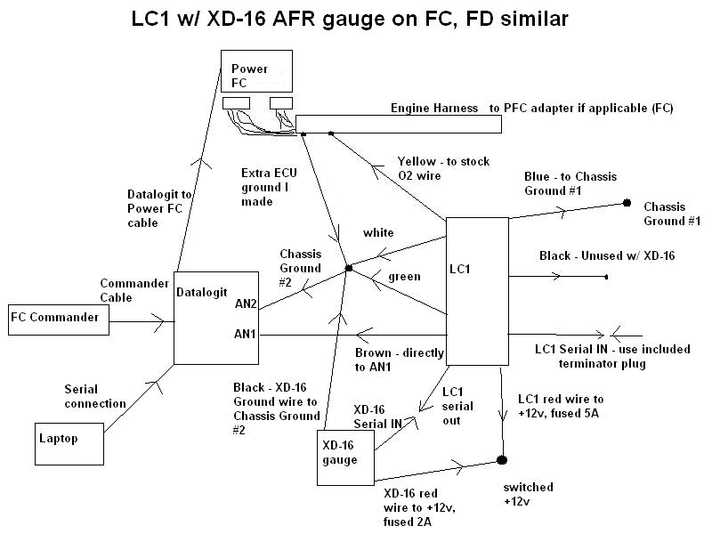
see https://www.rx7club.com/power-fc-forum-47/my-power-fc-lc-1-xd-16-datalogit-wiring-diagram-707298/ for more info. this setup has worked fine for me so far with no electrical noise or any of those kind of problems. I have a 7 wire unit but I believe you should separate the blue heater ground wire from the other grounds on both. With the key in the on position and the car off the datalogit should read full lean (once the sensor has warmed up. I think it reads full rich while it is warming up for a few seconds iirc, but I might be wrong).
or without a DL (again, FC and FD wiring are pretty much the same)
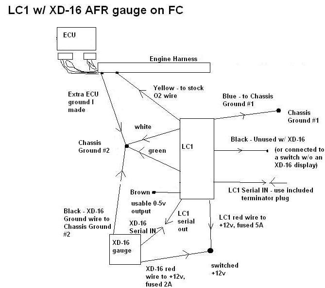
or without a DL (again, FC and FD wiring are pretty much the same)
Last edited by arghx; Mar 22, 2008 at 05:22 PM.
i just show 0 when i do a map watch for the AFR with the dattaloggit and the sensor fully warmed up.. though i checked the voltage with a voltmeter and it showed 4.96 volts so im thinking i dont have something checked in the dataloggit, i do have the an1 an2 setup right with 0 volt being 9 and 5 volt being 16. and i have the box checked so that an1 and an2 show up in the same box together as shown on the innovative website
I just took a closer look at the diagram. So the terminator plug stays in? i thought that was just when u calibrate it with a computer? I dont have the gauge... is the terminator plug only used for the gauge?
I just took a closer look at the diagram. So the terminator plug stays in? i thought that was just when u calibrate it with a computer? I dont have the gauge... is the terminator plug only used for the gauge?
Last edited by Dudemaaanownsanrx7; Mar 24, 2008 at 03:17 PM.

Senior Member
Joined: Oct 2002
Posts: 526
Likes: 5
From: Atlanta
--Jeff
http://www.innovatemotorsports.com/r...t_tutorial.pdf Read this tutorial. It explains a lot
The 0-5v output settings in the LC-1 need to match the scale in the 0-5v input setting in the DL. When I installed mine, I set the scale from 9:1 to 16:1 in both the LC-1 (using LM programmer) and the DL. And the terminator plug needs to be in during normal operation.
The 0-5v output settings in the LC-1 need to match the scale in the 0-5v input setting in the DL. When I installed mine, I set the scale from 9:1 to 16:1 in both the LC-1 (using LM programmer) and the DL. And the terminator plug needs to be in during normal operation.
Senior Member
Joined: Oct 2002
Posts: 526
Likes: 5
From: Atlanta
http://www.innovatemotorsports.com/r...t_tutorial.pdf Read this tutorial. It explains a lot
The 0-5v output settings in the LC-1 need to match the scale in the 0-5v input setting in the DL. When I installed mine, I set the scale from 9:1 to 16:1 in both the LC-1 (using LM programmer) and the DL. And the terminator plug needs to be in during normal operation.
The 0-5v output settings in the LC-1 need to match the scale in the 0-5v input setting in the DL. When I installed mine, I set the scale from 9:1 to 16:1 in both the LC-1 (using LM programmer) and the DL. And the terminator plug needs to be in during normal operation.
i also changed mine from 9- 16. i just did the same as innovative showed in their how to document for the lc-1 and dataloggit. I understand the idea is it gives you a better resolution. 9 should be fine as you dont need anything richer then that. i didnt know ppl were running afr's that much over 14.7:1 which is why 16 made sence to me. well all that can be changed very easily anyways with the serial cable. My lc-1 match the dataloggit values so that wont be an issue in my case..

I have the LC-1 and XD-1 integrated with the DL.
Unfortunately, I can't the the displayed AFR to match the logged ones via "map watch" on the DL.
They are about 3-points off.
Both the LC-1 analog outputs and the XD-1 are programmed for a scale of: 9 AFR (0v) and 16 AFR (5v).
I have tried it in both differential (AN1-AN2) and AN1 only (against ground hooked-up to 0v on DL), and get the same values.
I'm thinking my a,b,c values for poly are off.
I'm currently running: a=0, b=1.4, and c=9
I've also tried: a=0, b=1, and c=0.
What a,b,c values are people running and with what AFR range (9-22, or 9-16, etc.) ?
Thanks,
:-) neil
FWIW: SlvrRexx never got this answered:
I changed LC-1 analog output to 0vdc=9 and 5vdc=19
Then on the FC-Edit, Aux Setup, I changed the poly values for the wideband channel to:
a=0, b=2, c=9,
and now I'm within 0.3 of the XD-1 display.
Anyone have different values for poly ?
Thanks,
:-) neil
Then on the FC-Edit, Aux Setup, I changed the poly values for the wideband channel to:
a=0, b=2, c=9,
and now I'm within 0.3 of the XD-1 display.
Anyone have different values for poly ?
Thanks,
:-) neil