
Power FC Fires up / shut down

Fires up / shut down
Looking for ideas...Just installed PFC, DL, A/F gauge, boost gauge, LC-1. Car running V-mount, Greddy G20 turbo, 50m wastegate, 550/850's, Jacobs Ign.box, Blitz turbo timer,
On old/oem computer, car idled nicely....once I put in new items and downloaded map I got from Kam at Pettit, car fires up...stays on for 2-3 seconds then shuts down. Got spark, assuming fuel (no gauge for pressure yet), could it be something on map?...cut wrong wires from oem harness?...sensors?...hooked up LC-1 incorrectly?....
Any help is appreciated, thanks in advance.
Ruben
OK, I think I did everything I needed. At first, it stayed running a few seconds longer like it was learning the idle…then it shut down. Trying to fire it up again, back to what it was doing. Fires up…then shuts down.
My commander display is as follows: @ = blackened circle for sensor
PIM: 4.87v ! STR: 0 ! HWL: @
VTA1: .72v ! A/C: 0 ! FPD: 0
VTA2: 1.7v ! PWS: @ ! FPR: 0
VMOP: .91v ! NTR: @ ! APR: 0
WTRT: 2.83v ! CLT: 0 ! PAC: @
AIRT: 2.82v ! STP: 0 ! CCN: @
FUEL: 4.17v ! CAT: @ ! TCN: 0
O2S: .11 ! ELD: 0 ! PRC: 0
My wire hook up is as follows: maybe you see something I did wrong:
LC-1 WIRES:
Red: 12v switch
White: Ground / same as blue on LC-1
Blue: Ground
Brown: AN1 on DL
Black: To Calibration button/LED…have not got the LED to light up.
Yellow: To OEM O2 wire.
DL WIRES:
Ground wire to AN2
FC commander cable in / Cable to Power FC
Serial cable in to DL from Laptop
AN1 = Brown wire from LC-1
Gauge:
Red: Same 12v switch as LC-1
Black: Ground / same as blue & white
Yellow: ?
White: Spliced in to Brown wire from LC-1 to AN1 ?
Any more help would be appreciated. Thanks again.
Car is still shutting down almost immediately after starting up.
On the OEM computer, it idles nicely.

I dont know anything about PFC but I had the same problem with megasquirt. turned out I had the fuel pump trigger wired wrong. I had it going to the resistor relay instead. Check your pump voltage as someone starts it and see what happens


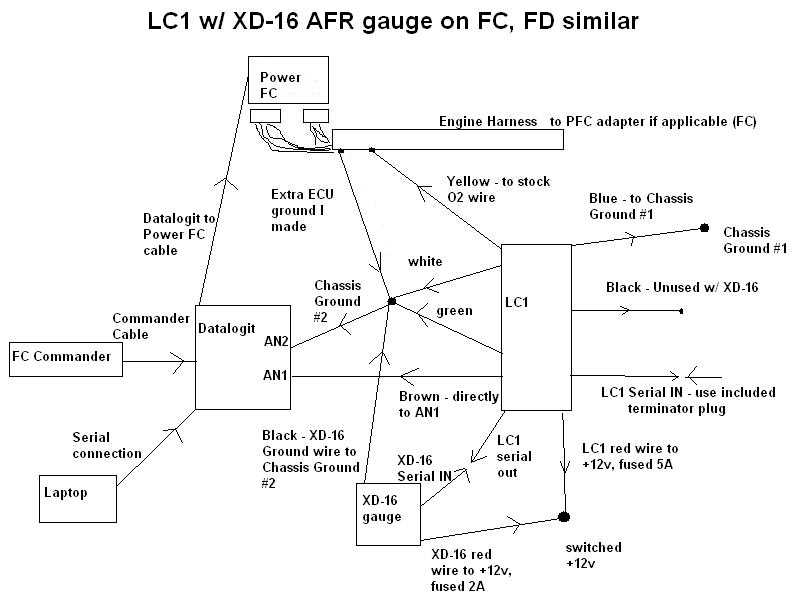
that's for those with the XD-16, which doesn't require a calibration switch. But the basic wiring is the same.
see this thread for greater detail: https://www.rx7club.com/power-fc-forum-47/my-power-fc-lc-1-xd-16-datalogit-wiring-diagram-707298/
LC-1 WIRES:
Red: 12v switch
White: Ground / same as blue on LC-1
Blue: Ground
Brown: AN1 on DL
Black: To Calibration button/LED�have not got the LED to light up.
Yellow: To OEM O2 wire.
Red: 12v switch
White: Ground / same as blue on LC-1
Blue: Ground
Brown: AN1 on DL
Black: To Calibration button/LED�have not got the LED to light up.
Yellow: To OEM O2 wire.
White should not be grounded in the same location as blue. Blue is a heater ground and can cause electrical noise. Yellow wire is pointless, you will have to disable the O2 sensor in the PFC anyway ("O2 Feedback" in settings 1 of the Datalogit). With the wiring I am suggesting, you have to enable the "Delta AN1-AN2" under the aux setup in the PFC. And you may want to use the Innovate software to adjust the Innovate signal output range. The LC-1 and the PFC have to agree.
I've never hooked up the analog Innovate gauge, but I think it needs to see a specific voltage scale to work right. You could probably use the brown output wire on the LC1 for both the DL and the gauge, but you have to make sure that the DL and the LC1 agree. The other option is to run the brown wire to the gauge, and run the yellow wire to the DL. Then adjust the yellow wire's output from a narrowband signal to a wideband signal (this is adjustable in the LC1 software). It sounds complicated, but really all you are doing is making sure that the input devices expect the same signal that the output device (LC1) is sending.
On old/oem computer, car idled nicely....once I put in new items and downloaded map I got from Kam at Pettit, car fires up...stays on for 2-3 seconds then shuts down.
The first thing that I notice is that your PIM voltage is about maxed out. The PFC thinks you are on almost max boost, and this is at idle!
Check you Map Sensor wiring.
The next thing is your TPS voltages are high.
Check you Map Sensor wiring.
The next thing is your TPS voltages are high.
If the fast idle cam has not disengaged (engine cold), the TPS voltages will read high. In this case if the car won't stay on it's likely those are cold voltages. That's why the factory TPS set procedure is to be done on a warm engine.

argxh,
the innovate manual says to ground ALL the grounds together at the same point. in fact they have a dedicated instruction on why you want to ground all at the same point.
what i am missing here?
"The BLUE and WHITE wires should all be grounded to the same ground source.
Optimally, these (and any other MTS device ground) will be soldered to the same lug, and
connected to a single point. When this isn’t possible, connect each one to a separate lug,
and attach in close proximity. Multiple lugs on the same bolt is not optimal, and can result in
unwanted signal “noise.” When possible, soldering is always better than crimping. Please
see chapter 2.3 for more information on Electrical Grounding Concerns.
6. Optionally, the YELLOW (Analog out 1) and/or BROWN (Analog out 2) can be connected
to the analog inputs of other devices such as data loggers, ECUs, or gauges. If either one or
both of these wires are not being used isolate and tape the wire(s) out of the way. The default
analog outputs are as follows: Analog output one is 1.1V = 14 AFR and .1V = 15 AFR. This is
a simulated narrowband signal. Analog output two is setup as 0V = 7.35 AFR and 5V = 22.39
AFR. Note: The LC-1’s heater ground and system ground wires should share the same
grounding location of the analog input’s ground. Refer to chapter 2.2 for recommended
wiring schematics."
Trending Topics
The blue wire is a heater ground, and it makes no difference in it's opperation where it's grounded. It's been recommended to keep it separate because it pulls a higher current and could skew the readings when connected to the system ground. The innovative instructions is about clear as mud in many areas, it also contradicts itself in a few spots.
Basically keep any datalogger and system grounds together. Keep the heater ground separate and you'll be good to go.
Basically keep any datalogger and system grounds together. Keep the heater ground separate and you'll be good to go.
I made that diagram over two years ago. I am looking back through my source information (manuals and various threads)
https://www.rx7club.com/showpost.php...7&postcount=76
in hindsight... the exact placement of the blue one doesn't matter so much I guess. Maybe I've been making a big deal about it and I apologize if that has caused problems or confusion. Again, that was two years ago.
The more important stuff is common grounding between the Datalogit, the ECU, and the display gauge. You will notice how meticulous I was in the diagram about that. My main ECU ground wires have been run to the same ground as the LC-1 white and green wires, as well as the ground for the display gauge. The ECU extra ground probably isn't necessary but grounding the display gauge to the same place as the Datalogit and the LC-1 I think is important.
https://www.rx7club.com/showpost.php...7&postcount=76
Hi,
Seems there is a lot of confusion about grounding the LC-1. First some background:
Any current flowing through a wire causes a voltage on that wire. If the wire is a ground wire, that voltage is invisible to the device at the other end (LC-1) and it would reference that point as ground. This means that another devive on the other end of the wire will reference a different ground point and there is a voltage offset between the devices. This is called ground offset. The bigger the current, the bigger that voltage. Because the heater of the sensor draws a relatively large current, it would correspondingly create a large offset. Therefore the LC-1 has multiple grounds. The heater ground (blue wire) can be connected to any convenient chassis ground, because the only thing in the LC-1 that references to it is the heater, and it is not critical.
On a 7-wire LC-1:
The system ground (white) and analog out ground (green) should be connected together and to the ECU or datalogger ground. This way the ground offsets are minimized. If an analog AFR display is used on one of the analog outs, IT's ground should ALSO be connected to the same ground point where system (white) and analog out (green) ground are connected.
On a 6-wire LC-1:
The system/analog out ground (metallic) should be connected to the ECU or datalogger ground. This way the ground offsets are minimized. If an analog AFR display is used on one of the analog outs, IT's ground should ALSO be connected to the same ground point where system/analog out ground (metallic) is connected.
On both LC-1 types:
- Red is switched 12V power
- Yellow is Analog out 1, with the default programming simulating a NBO2 sensor. Leave open and insulated if not used
- Brown is Analog out 2. with the default programming it outputs a linear voltage from 7.35 AFR (Lambda 0.5) at 0 Volt to 22.4 AFR (Lambda 1.523) at 5V. Leave open and insulated if not used.
- Black is the calibration wire. Connect momentarily to ground to calibrated, otherwise leave open. Alternatively you can connect a LED between this and ground to show the LC-1 status.
If an XD-1 is used, it should be grounded ALSO to the same point where the system and analog out grounds are grounded.
Hope this clears it up.
Regards,
Klaus
in hindsight... the exact placement of the blue one doesn't matter so much I guess. Maybe I've been making a big deal about it and I apologize if that has caused problems or confusion. Again, that was two years ago.
The more important stuff is common grounding between the Datalogit, the ECU, and the display gauge. You will notice how meticulous I was in the diagram about that. My main ECU ground wires have been run to the same ground as the LC-1 white and green wires, as well as the ground for the display gauge. The ECU extra ground probably isn't necessary but grounding the display gauge to the same place as the Datalogit and the LC-1 I think is important.
hi,
what exactly do you mean by the "ecu ground" ?
the pfc and factory harness have grounds only on the engine block. there is a small ground wire inside the cabin by the ecu but this grounds the sheilding of the crank sensor wires.it have nothing to do with ecu ground.is that what you mean by the "ecu ground"?
what can i do to ground the ecu and datalogit-lc1 together? run a cable to the engine block where the ecu ground is?
i simply ground the lc1 and datalogit on an ecu mouting bolt (the pfc is also bolted on there with metal brackets)
is it enouth?
thanks for any info and help!!
?
What is the "factory TPS set procedure? Can I do this?
Another concern of mine is, the LED for the LC-1 and calibration wire has not lit up yet....
it's a common mod on 2nd gens with hesitations on stock ECU, that's why I did it. There are four ground wires on the 2nd gen harness that come together to two wires at factory crimps near the ECU. Then the two factory wires ground under the UIM in the stock location. I took a wire and ran it through those two crimp points (didn't disturb the factory crimps) in series, then grounded it to a bolt near the ECU. I ran my LC1 ground wires to that same point. It's probably not necessary. 2nd gen owners know what I'm talking about. I don't think you could easily do that on the FD harness but I could be wrong, I have messed with FD harnesses but I've never unwrapped one.
Notice how in my diagram it says "extra ECU ground I made," which was meant to imply that it is an redundant thing that I did on my car. I guess in my previous post I made it sound more important than it is.
workshop manual, fuel and emissions control section. you really need to become familiar with this section.
Notice how in my diagram it says "extra ECU ground I made," which was meant to imply that it is an redundant thing that I did on my car. I guess in my previous post I made it sound more important than it is.
What is the "factory TPS set procedure? Can I do this?
Yeah i figured there was a reason. You don't seem like the type to arbitrarily add stuff without a reason. I was just stating for the lc1 it's not required for proper opperation since he was asking how to add the ground.

Thread
Thread Starter
Forum
Replies
Last Post
ls1swap
3rd Generation Specific (1993-2002)
17
Jun 3, 2024 03:25 PM
LongDuck
1st Generation Specific (1979-1985)
12
Oct 7, 2015 08:12 PM