
Help with 91' headlights


Thread Starter
Junior Member
Joined: Sep 2013
Posts: 6
Likes: 0
From: California
Hello everyone,
My name is Spencer, and I'm from California. This is my first thread on the forums, so hopefully this all makes sense, I read the instructions fairly carefully and think I managed to comply with all the instructions!
I have a question regarding the headlight function on our family's stock '91 NA convertible rx7. It's completely stock but not in great condition. The main issue we have with it currently is it's headlight operation.
When the headlight switch (Left hand column switch) stopped working we purchased a couple of replacements that performed only one or two operations (ie lights up but not down, lights off but not on etc.) However, between the number of switches we have obtained, we have one that will perform each of the major functions needed to make the headlights operate. Utilizing the different switches i can confirm that both headlights and headlight motors all do work, but not always in a predictable manner (likely due to the switches).
One of the switches will perform the desired operation only when the wiring harness is plugged into it initially (i.e. if lights are set to up and on when you plug it in, the car will respond appropriately). After the initial plug in, it does nothing. The other switches perform similarly.
I have consulted a number of other websites in my search for a solution, here are some of my resources:
How To Add Daytime Running Lights
https://www.rx7club.com/3rd-generati...-lights-87264/
http://www.rotaryheads.com/PDF/2nd_g...cal_system.pdf
I've attempted to probe the switches with a multi-meter in order to determine if they are functional, but my probes haven't sat well in the connectors, so i can't tell if my issue is really at the switch level.
Based on what i understand from the wiring diagram, there are a number of switches that directly connect two wires to perform an operation, and perhaps if I could wire these together with switches i could bypass the switch entirely. I don't care much about the resale value or stock appearance, so wiring in a few toggle switches/ relays is fine. From what i understand i could either attempt to connect wires at the switch level or patch into the 12 volts somewhere along the system (perhaps at the ignition) and use this to drive the headlights and pop-up motors with fuses inline along the lines of this video:
If someone could guide me in the right direction to fixing the problem it would be much appreciated!
Thread Starter
Junior Member
Joined: Sep 2013
Posts: 6
Likes: 0
From: California
Joined: Sep 2005
Posts: 25,581
Likes: 136
From: Smiths Falls.(near Ottawa!.Mapquest IT!)
Unfortunately I am not a wiring guru or an S5 guy( 2 strikes right there..lol!
But there is a SEC GEN Spceific section and a Guy named SATCH that may be able to help you..( 2 homeruns..!)
But there is a SEC GEN Spceific section and a Guy named SATCH that may be able to help you..( 2 homeruns..!)

The Red wire in the Headlight harness provides constant voltage to the switch and is powered by the Head fuse. There are two wires specifically related to the retractors and they are Red/Yellow and Red/Blue also found in the Headlight harness. When R/Y has voltage and R/L does not the lights will go down. When the opposite is true the lights will go up. And there is a fourth wire to the retractors which is a ground wire and it is Black. If this wire were iffy it could cause an issue w/the lights popping up when they should. But if this wire were sound then the issue is likely found within the switch.
As far as turning on the lights when the **** is turned fully the switch places a ground on the Red/White wire in the harness. This wire connects to a White/Blue wire that runs to the Headlight Relay. If you locate this relay (has four wires: two red, one WL and one Red/Green) and place a ground on the W/L wire then the lights should turn on (not pop up but turn on). If this were the case then the problem of the switch is it obviously is not placing the ground on the R/W wire. So, if you were to bypass this aspect of the relay then connecting the R/W wire to a toggle switch such that the other wire connected to the toggle has a ground to it should allow you to manually control when the lights are to turn on and when to turn off.
As far as turning on the lights when the **** is turned fully the switch places a ground on the Red/White wire in the harness. This wire connects to a White/Blue wire that runs to the Headlight Relay. If you locate this relay (has four wires: two red, one WL and one Red/Green) and place a ground on the W/L wire then the lights should turn on (not pop up but turn on). If this were the case then the problem of the switch is it obviously is not placing the ground on the R/W wire. So, if you were to bypass this aspect of the relay then connecting the R/W wire to a toggle switch such that the other wire connected to the toggle has a ground to it should allow you to manually control when the lights are to turn on and when to turn off.
Last edited by satch; Sep 16, 2013 at 04:18 PM.
Thread Starter
Junior Member
Joined: Sep 2013
Posts: 6
Likes: 0
From: California
Thanks for your detailed and immensely helpful reply! Before I go around sticking wires into my rx7, i wanted to ask a few clarifying questions and confirm i'm looking at the right wires.
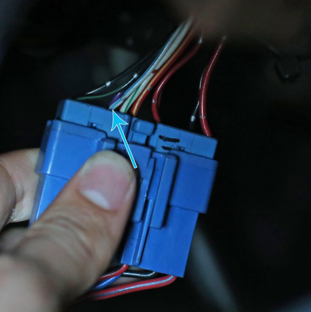
1) I know this sounds silly but lets confirm we're talking about the same wiring harness here.
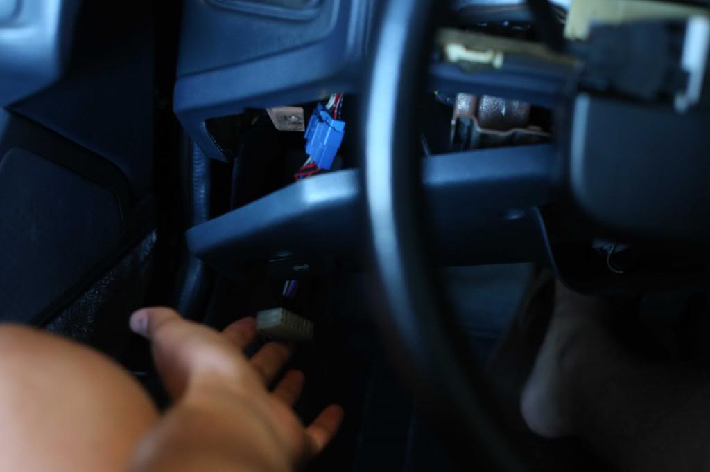
Good? Good.
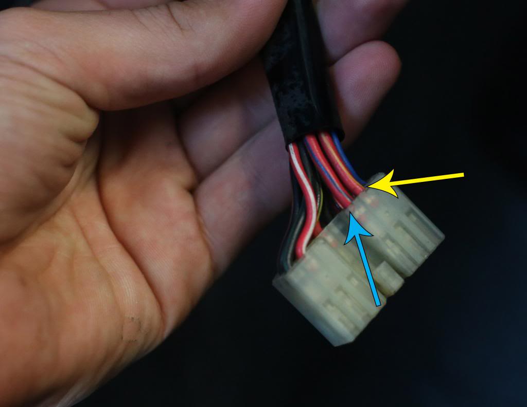
2) Let's make sure the Red + Yellow Wire and Red + Blue wires are the ones i think they are. Additionally, when you say "When R/Y has voltage and R/L does not the lights will go down" I'm assuming you mean R/B instead of R/L, correct me if I'm wrong
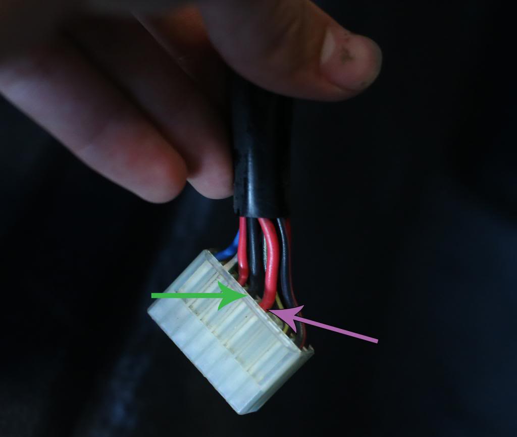
3) Can we confirm that the wires I think are VCC and Ground are indeed those? Pink being 12v source and green being ground
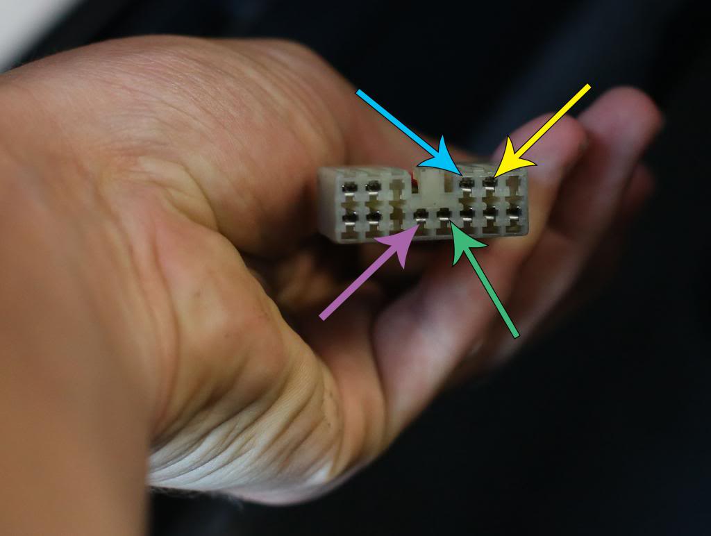
4) Lets make sure I'm understanding the harness positions correctly, because they contradict the manual i found online. Would you agree with all these positions as the correct places? Colors correspond to the previous images.
5) As far as I understand, I won't need to tinker with the White/Blue wire, but in case i do let's confirm that this is the one while we're at it.
Now for my more wordy questions:
If I understand correctly, I could put the 12v source into the center of a SPDT switch, and then flipping it would cause the lights to go up or down. Should the two pins stay connected or once the motor moves the lights does it need to be disconnected? Additionally, how many amps should the switch be rated for?.
Pardon my ignorance, but a google search has failed me, what does WL stand for? And in order to place a ground should I connect to a chassis bolt and then the relay?
How would you check if this wire is iffy? I have a multimeter so I could check continuity in a couple of places (like ground wire to chassis ground) if that's helpful? Where exactly should i being checking for aforementioned iffy-ness (switch, harness, etc.)?
Many thanks for your wisdom, sorry for asking so many questions, but I'd rather not blow something up and regret it afterwords. I'm happy to gift you a drink via pay-pal if you want it
1) I know this sounds silly but lets confirm we're talking about the same wiring harness here.

Good? Good.
2) Let's make sure the Red + Yellow Wire and Red + Blue wires are the ones i think they are. Additionally, when you say "When R/Y has voltage and R/L does not the lights will go down" I'm assuming you mean R/B instead of R/L, correct me if I'm wrong

3) Can we confirm that the wires I think are VCC and Ground are indeed those? Pink being 12v source and green being ground

4) Lets make sure I'm understanding the harness positions correctly, because they contradict the manual i found online. Would you agree with all these positions as the correct places? Colors correspond to the previous images.

5) As far as I understand, I won't need to tinker with the White/Blue wire, but in case i do let's confirm that this is the one while we're at it.

Now for my more wordy questions:
Many thanks for your wisdom, sorry for asking so many questions, but I'd rather not blow something up and regret it afterwords. I'm happy to gift you a drink via pay-pal if you want it
B=Black and L=Blue as you can't have B equal Black at certain times but Blue on other occasions as it would be rather confusing.
The Red/Yellow wire at the Headlight Switch eventually mates at connector X-17 w/the White/Blue wire (W/L). You would have to look in the FSM for the location of X-17 but it's not necessary because R/W would be found at the switch harness.
A bit of education tip here. A continuity test would tell you if by chance that W/L wire is the W/L found at the Headlight Relay.
Last edited by satch; Sep 16, 2013 at 09:03 PM.
Trending Topics
Thread Starter
Junior Member
Joined: Sep 2013
Posts: 6
Likes: 0
From: California
B=Black and L=Blue as you can't have B equal Black at certain times but Blue on other occasions as it would be rather confusing.
The Red/Yellow wire at the Headlight Switch eventually mates at connector X-17 w/the White/Blue wire (W/L). You would have to look in the FSM for the location of X-17 but it's not necessary because R/W would be found at the switch harness.
A bit of education tip here. A continuity test would tell you if by chance that W/L wire is the W/L found at the Headlight Relay.
The Red/Yellow wire at the Headlight Switch eventually mates at connector X-17 w/the White/Blue wire (W/L). You would have to look in the FSM for the location of X-17 but it's not necessary because R/W would be found at the switch harness.
A bit of education tip here. A continuity test would tell you if by chance that W/L wire is the W/L found at the Headlight Relay.
Excellent stuff! The L designation makes way more sense now

Would you mind confirming this question for me? Thanks so much!
If I understand correctly, I could put the 12v source into the center of a SPDT switch, and then flipping it would cause the lights to go up or down. Should the two pins stay connected or once the motor moves the lights does it need to be disconnected? Additionally, how many amps should the switch be rated for?.
Another telling factor is what does the W/L wire mate with? If it mates with a Red/White wire then chances are you have the correct plug.
When the car is just sitting there minding its own business the voltage from the Red wire in the harness is passed on to the Red/Yellow wire to keep the headlight in the down position so if you want the lights to stay down then you must have voltage running to the R/Y wire. Again, as previously stated, the voltage from the Red wire is constant voltage (24/7 as powered by the Head fuse).
When the lights are required to be in the up position the voltage currently found on the R/Y wire must cease and this voltage must then be passed to the Red/Blue wire (R/L).
You can validate this process by unplugging the retractor 4 wire plug which each retractor has and place voltage on the R/L wire and a ground on the Black wire and if the lights are in the down position they should pop up. And the White/Green wire at each retractor plug should be powered by the Retractor fuse (constant voltage).
And the Black wire in the plug w/the W/L wire is a ground. Jumper a wire from one wire to the other and the lights should come on.
If you pull the voltage off of the R/L wire and the lights continue to stay up then place voltage on the R/Y wire and the lights should retract downward (I'm talking about one headlight here as both have their own 4 wire plug). Since the Red wire powered by the 30 amp Head fuse has 30 amps then a maximum of 30 amps should be used. And you can use the Red wire for the throw switches.
Last edited by satch; Sep 16, 2013 at 09:41 PM.
In theory you can take two wires and crimp them together to a spade. Take the spade and shove it into the back of either side of X-17 and you then have constant voltage on two separate wires which can be ran to a couple of throw switches. Next step would be to depin/remove the R/Y and R/L wires from the front side of X-17 which is the side w/the White/Blue wire. Once removed one wire goes to the other side of one throw switch and the remaining wire goes to the other throw switch. If the switch w/the R/Y wire is in the on position then the lights should be in the down position. Flip this switch to the off position and do the opposite to the other throw switch and the lights should retract.
Another switch which is connected to the Black wire in X-17 and the W/L wire connected to the other side of the throw switch and w/the switch placed to the on position the lights should be turned on.
And you never mentioned if the Headlight Switch operates the dash lights as well as the running lights in a proper fashion.
Thread Starter
Junior Member
Joined: Sep 2013
Posts: 6
Likes: 0
From: California
Many thanks for the extremely helpful advice! I have a toggle switch all wired in and everything works great! I'll post some photos and possibly video in case anyone needs to repeat the process in the future.

Thread
Thread Starter
Forum
Replies
Last Post
renjiv2
3rd Generation Specific (1993-2002)
57
Jan 25, 2024 03:34 AM
FC3S Timmy
2nd Generation Specific (1986-1992)
16
Oct 3, 2015 01:08 AM