
Cat/Air Pump schematic


Thread Starter
Junior Member
Joined: Jan 2011
Posts: 35
Likes: 0
From: New London, CT
Cat/Air Pump schematic
Can someone provide me with a diagram for the emissions control systems on an 89 NA? Poking around online and through my Haynes manual didn't yield a clear picture of what's going on.
The short of it is that I bought the car not realizing most of the emissions stuff was removed, and in order to pass emissions and register, and I need to replace (at least) the catalytic converter and the air pump.
Now, I know those are the 2 major parts I need, but I need to figure out all the little things that go along with it. The various hoses, belts, split air pipe, ACV, etc. Things I've heard mentioned and don't know exactly what they look like or where they should go (some of the stuff might still be hanging out in there and disconnected, but I'm not sure what to look for). Unfortunately, looks like the previous owner is ducking my calls so I can't ask exactly what he removed, making this whole thing into an ugly mess.
Alternate question: rather than spend time trying to figure out how Mazda had wired the air pump and various valves together to supply the cat with air under such and such conditions, is there something like some kind of electric air pump that I can basically plug in 12V on one side, and put a hose to the cat on the other?
The FSM is what you want. There are links in the FAQ, or you can go here: http://mazdarx7.iougs.com/emissions.shtml. This page also has some diagrams (from the FSM) and explanation of the emissions system. This is for an S4 NA, but it is nearly identical. The biggest difference is S5s do not have EGR valves.
If the previous owner left the emissions rack in place, you'll just need an ACV, air pump, cat, and some time scouring the vacuum diagram in the FSM. The split air pipe is useful for passing visual inspection, but it is actually not the primary source of air delivery to the main cat. In any gear but 5th, the split air path only has a 1/16" opening feeding it inside the ACV, while the port air path is about a 1" hole. The port air path (as in exhaust ports) is the more important of the two.
In other words, hooking up an electric air pump directly to the main cat would not be as effective as running it to the exhaust ports like the stock system does.
Thread Starter
Junior Member
Joined: Jan 2011
Posts: 35
Likes: 0
From: New London, CT
Well, reading through the FSM and poking around a bit more has helped me understand more about it. If I'm understanding it right, all (right...all) I need to do is replace the straight pipe with a cat, install the air pump on the top side of the engine, connect a belt, install the ACV on the lower intake manifold, and connect all the junk together with vacuum hose.
This leaves me with a few questions:
1) What kind of hose do I use for all the connections? Googling didn't yield any result for specialized exhaust system vacuum hose or anything like that.
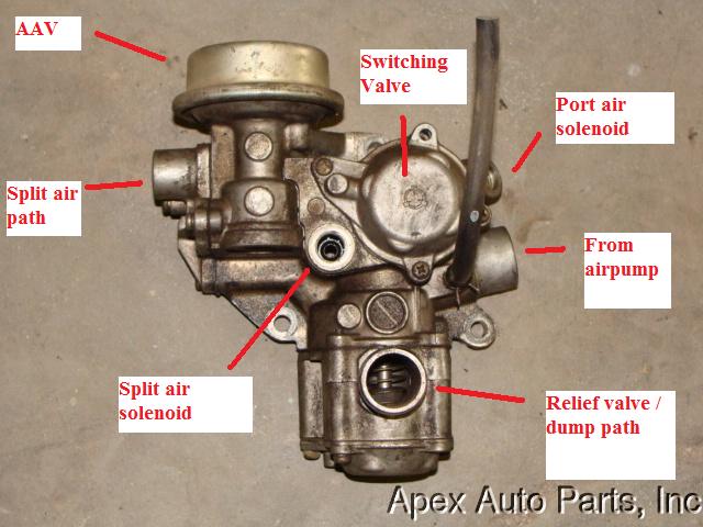
2) I had actually already stumbled on the link you provided, which seemed to leave more questions than answers. After staring, it's making a bit more sense, but one question stands out. The first picture on the page lists the ACV the top, above the AAV. Are they trying instead to show that the whole big assembly is considered the ACV? While ebaying up parts, I found this ACV http://imagehost.vendio.com/bin/view...&vsid=87&vgp=1
which, with some artistic license, looks kinda like that whole mishmash of AAV and the various solenoids and relief valves.
3) An obviously green question, what is the "emissions rack" you referred to? I have no idea what to look for to know whether or not it's there.
Thanks for the help.
This leaves me with a few questions:
1) What kind of hose do I use for all the connections? Googling didn't yield any result for specialized exhaust system vacuum hose or anything like that.
2) I had actually already stumbled on the link you provided, which seemed to leave more questions than answers. After staring, it's making a bit more sense, but one question stands out. The first picture on the page lists the ACV the top, above the AAV. Are they trying instead to show that the whole big assembly is considered the ACV? While ebaying up parts, I found this ACV http://imagehost.vendio.com/bin/view...&vsid=87&vgp=1
which, with some artistic license, looks kinda like that whole mishmash of AAV and the various solenoids and relief valves.
3) An obviously green question, what is the "emissions rack" you referred to? I have no idea what to look for to know whether or not it's there.
Thanks for the help.
1) For the handful of ACV connections, use standard 3.5mm vacuum hose. Nothing special. To hook up a split air pipe, you can use some generic emissions/heater hose.
2) The AAV is just part of the ACV. The diagram at the top of the page in that link is a blown up view of the ACV, and the things it connects to. The relief valve, switching valve, split air valve & port air valve are all inside the ACV. The split air and port air solenoids are on the outside of the ACV, and have plugs that connect up to the harness. I've labeled the picture you linked to, but I can already see the split air and port air solenoids are missing. You could thread some bolts into the openings and still pass smog. Their use is limited; however I think you'll end up with the check engine light coming on: http://www.johnr.com/cpucodes.html. This could fail you.
3) The emissions rack is just what's attached to the top of the block (under the intake manifold), that has all of the vacuum lines and fuel lines routed through it. There would be something like 5 large black solenoids with colored plugs attached.
Now something else to consider...
With no air pump and no ACV, your S5 NA is almost definitely suffering from a severe lack of power. The auxilliary intake port actuators and VDI (variable dynamic intake) actuator are activated by solenoid using air pump pressure. They're responsible for approx. 40HP. There's the possibility that someone "wired" everything open, which means low RPM torque will suck.
Thread Starter
Junior Member
Joined: Jan 2011
Posts: 35
Likes: 0
From: New London, CT
Thanks for clearing a lot of things up. Since they kept referring to the "air control VALVE", I assumed it was a single valve and not the whole assembly. I have a clearer picture now of what is going on, and that labeled diagram you provided is a major help.
I'll have to see about that emissions rack when I get home. Hopefully it's intact, because I've got about 2 weekends to get my car through emissions and don't want to have to reassemble too much.
You mentioned originally that the port air path is the most important for the emissions test, so wouldn't the port air solenoid be important to have?
And, you hit the nail on the head about the ports. I believe they were wired open, and since I intended to turn this into an autox car, that low end torque issue is no bueno. My primary concern is getting through emissions at the moment, but that's definitely a priority once she's passed emissions and been registered. I'm going to have to hunt down exactly how he opened them and put them back to the way they were, unless there's some other alternative to getting that power back.
Why is it that so many people opt for this emissions system/air pump removal stuff when it seems to have little to no benefit? I could understand removing a cat trying to get a few additional hp, but I can't imagine reducing a bit of pull on the engine by removing the air pump makes up 40 hp of lost low-end torque...
The port air solenoid is an odd one. After the car has 20,000 miles, the solenoid will always be in the open position. This allows a little bit of extra air to flow to the port air path, but it's not the main source. If you take a look at that FSM diagram, you'll see the primary source for port air is much larger & regulated by the switching valve/solenoid (and indirectly by the relief valve/solenoid). If you haven't looked through the S5 FSM yet, take a look here for more pictures and explanations: http://www.rotaryheads.com/PDF/2nd_g..._non_turbo.pdf
Too many people get it in their head that they can somehow make the car lighter and faster by removing everything possible. But unfortunately most of those people don't bother to read up on the purpose of those things they want to remove. There are a lot of things that get confused with the emissions equipment (like idle control systems: BAC & thermowax).
With your 6PI wired open, you lose some torque under 3800 RPM. With your VDI wired open, your intake manifold will permanently be a short-runner design, which saps torque under 5200 RPM. So if you plan to always be between 5200 RPM and redline, it's unnoticeable . But for those of us that live in the real world, it's a stupid modification.
Too many people get it in their head that they can somehow make the car lighter and faster by removing everything possible. But unfortunately most of those people don't bother to read up on the purpose of those things they want to remove. There are a lot of things that get confused with the emissions equipment (like idle control systems: BAC & thermowax).
With your 6PI wired open, you lose some torque under 3800 RPM. With your VDI wired open, your intake manifold will permanently be a short-runner design, which saps torque under 5200 RPM. So if you plan to always be between 5200 RPM and redline, it's unnoticeable
. But for those of us that live in the real world, it's a stupid modification.
Thread Starter
Junior Member
Joined: Jan 2011
Posts: 35
Likes: 0
From: New London, CT
Alright, got a magnaflow cat in hand, and an ACV and pump on the way. Just need to track down a belt and some 3.5mm vacuum line and I should hopefully be able to get through emissions with some work. So, unless there's something else you think I should know, I will just spend the next several nights in bed cuddling with the FSM and next weekend I will hopefully have parts in hand and the time to install them.
Haven't yet tried to remove the intake manifold to look for that emissions rack, so hopefully it's there and I'll find it when I open her up next week.
Haven't yet tried to remove the intake manifold to look for that emissions rack, so hopefully it's there and I'll find it when I open her up next week.
Trending Topics
Thread Starter
Junior Member
Joined: Jan 2011
Posts: 35
Likes: 0
From: New London, CT
Well, an update of sorts. So, the emissions rack, is that what people keep referring to as the rat's nest? If so, that's gone. Is there a more proper name that it goes by? Can't find any mention of it on ebay and need to get a replacement somehow. Starting to get nervous that this may be a bit of a technical leap for me. Hopefully it'll be clearer once I've got parts in hand and the manual in front of me, and I can start matching pictures to things...
This should be helpful:
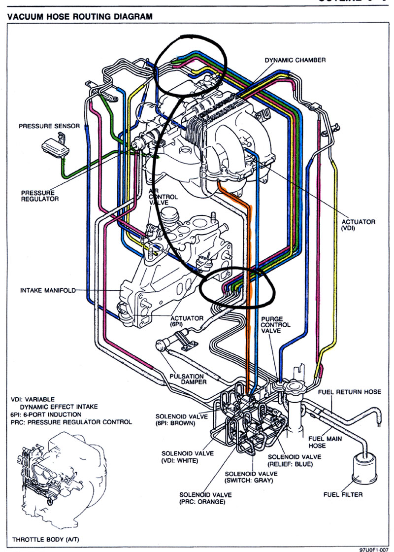
From this thread: https://www.rx7club.com/showthread.p...vacuum+diagram.
The emissions rack is all of the metal hardlines for vacuum & fuel routing, as well as the mounting locations for all of the solenoids (FPR, Relief, Switching, 6PI, VDI). On an S5 NA, there are also a couple smaller sections of hardlines, which are near the throttle body and near the ACV.
Thread Starter
Junior Member
Joined: Jan 2011
Posts: 35
Likes: 0
From: New London, CT
Cool. I've seen that picture in my manual, but the added colors help a lot. From the sounds of it, removing the emissions rack would require rerouting fuel lines too, which I would hope means that it wasn't done.
Sorry to repeat myself, but I still am not sure what the answer is: is there a more proper name for the rat's nest? Hard to try and find a replacement part for something that I don't know what to call it. All I know is that it isn't there
And once again, I really appreciate all the guidance you're giving me. If I get this thing running through emissions (and with the proper amount of low end torque after fixing the port actuators), I'll owe you at least a drink.
I don't know it by any name other than "emissions rack" or "rats nest". The Rx-7 parts fiche calls it "vacuum pipe". http://www.rotaryheads.com/PDF/2nd_g...0%20ENGINE.pdf (emissions control system section).
Here are the Mazda PNs and names for all 3 pieces:
Vacuum pipe, N350-20-410C (main rack)
Vacuum pipe #2, N350-20-41XA or N350-20-41XB
Air-valve actuator pipe, N350-20-41YA or N350-20-41YB
The postal service doesn't like it when people try to mail alcohol, so you might have to hold off on that one.
Here are the Mazda PNs and names for all 3 pieces:
Vacuum pipe, N350-20-410C (main rack)
Vacuum pipe #2, N350-20-41XA or N350-20-41XB
Air-valve actuator pipe, N350-20-41YA or N350-20-41YB
The postal service doesn't like it when people try to mail alcohol, so you might have to hold off on that one.
Thread Starter
Junior Member
Joined: Jan 2011
Posts: 35
Likes: 0
From: New London, CT
Well, I could just mail you some apple juice, and maybe it'll ferment en route.
After spending all this time trying to figure out how to put my car back to the way it was, I had a realization. My primary goal is to get through emissions before my car becomes illegal to drive, meaning I don't necessarily need a complete system at the moment. Putting it back completely to regain lost low end torque is secondary and can be a spring project. Trying to track down a solenoid rack or rat's nest or any of those spider pipes also proved difficult.
So, I'm wondering, assuming all I wanted to do was get my emissions passed, couldn't I succeed with just a cat, air pump, and ACV with the all the vacuum ports capped with the exception of the air pump intake and the port air path? Or, even crazier, with no ACV and just a hose stuck from the air pump to the exhaust port air path? From all the vacuum diagrams and the 8000 pages I poured over today explaining the operation of the dozen or so solenoids and all the operating regions, it sounds like essentially for what I'm interested in (a few minutes at <3000 rpm) I only need really need air shoved into that one port, and all the other solenoids and air paths are just bells and whistles that make it run better.
Am I insane/way off about something?
I think it would depend on what your emission test consists of. Here in CA we have a visual test, as well as 2-speed (15mph/25mph) dyno tests. Having a bunch of capped off things under the hood is an insta-fail around here. But I do know that some people have succeeded in running a hose from the air pump directly to the main cat. Routing it to the port air path in the ACV should do even better. The relief valve is defaulted closed, and I think the port path is the default for the switching valve. So without their solenoids, they should be in the positions you want.
Thread Starter
Junior Member
Joined: Jan 2011
Posts: 35
Likes: 0
From: New London, CT
So, it's been a while, but I was traveling a lot and never got around to finishing the fix. Got the air pump installed today, and am in the process of trying to get the block-off plates off (what did he use, superglue?). A couple of questions arose, things I wasn't entirely clear on but hoped would reveal themselves to me.
One, the labeled picture you provided above didn't mention the port air path. Is that the just on the back side, the part that mounts on where the block off plate currently is?
Two, when I blow into the intake, air comes out of the relief valve, and seemingly nowhere else. I would guess that means that it defaults to open, and closes at some other point. So, your earlier statement about the thing sitting exactly how I needed it, is that still true?
Three, there is at least one vacuum hose coming out of the back of the motor that has been blocked off. I have no idea what it's for, or whether I need to touch it. From the vacuum diagram I would guess that it maybe goes to the purge valve. Are there any other diagrams that might make it clearer what's what on the motor? I mean, people keep mentioning ports to me, and I don't even know where those are.
1)The port air path is the large, check-valved opening on the back side. It's not labeled because you can't see it in the pic. You might be missing the check valve that sits in the opening & prevents exhaust from damaging the air pump.
2)By intake, you mean the inlet on the ACV? The diagram I linked to in post #2 shows the relief valve in the open position (air dumped out), and with vacuum applied should close. At idle and under 3500 RPM the valve should be closed most of the time.
3)That diagram is about as good as it gets. 2 connections on the back of the TB are for the PCV. One is vacuum (blue), and the other comes out before the throttle plates I believe (yellow or pink).

Junior Member
Joined: Apr 2020
Posts: 21
Likes: 1
From: Florida
1) For the handful of ACV connections, use standard 3.5mm vacuum hose. Nothing special. To hook up a split air pipe, you can use some generic emissions/heater hose.
2) The AAV is just part of the ACV. The diagram at the top of the page in that link is a blown up view of the ACV, and the things it connects to. The relief valve, switching valve, split air valve & port air valve are all inside the ACV. The split air and port air solenoids are on the outside of the ACV, and have plugs that connect up to the harness. I've labeled the picture you linked to, but I can already see the split air and port air solenoids are missing. You could thread some bolts into the openings and still pass smog. Their use is limited; however I think you'll end up with the check engine light coming on: http://www.johnr.com/cpucodes.html. This could fail you.
3) The emissions rack is just what's attached to the top of the block (under the intake manifold), that has all of the vacuum lines and fuel lines routed through it. There would be something like 5 large black solenoids with colored plugs attached.
Now something else to consider...
With no air pump and no ACV, your S5 NA is almost definitely suffering from a severe lack of power. The auxilliary intake port actuators and VDI (variable dynamic intake) actuator are activated by solenoid using air pump pressure. They're responsible for approx. 40HP. There's the possibility that someone "wired" everything open, which means low RPM torque will suck.
2) The AAV is just part of the ACV. The diagram at the top of the page in that link is a blown up view of the ACV, and the things it connects to. The relief valve, switching valve, split air valve & port air valve are all inside the ACV. The split air and port air solenoids are on the outside of the ACV, and have plugs that connect up to the harness. I've labeled the picture you linked to, but I can already see the split air and port air solenoids are missing. You could thread some bolts into the openings and still pass smog. Their use is limited; however I think you'll end up with the check engine light coming on: http://www.johnr.com/cpucodes.html. This could fail you.
3) The emissions rack is just what's attached to the top of the block (under the intake manifold), that has all of the vacuum lines and fuel lines routed through it. There would be something like 5 large black solenoids with colored plugs attached.
Now something else to consider...
With no air pump and no ACV, your S5 NA is almost definitely suffering from a severe lack of power. The auxilliary intake port actuators and VDI (variable dynamic intake) actuator are activated by solenoid using air pump pressure. They're responsible for approx. 40HP. There's the possibility that someone "wired" everything open, which means low RPM torque will suck.

Junior Member
Joined: Jan 2022
Posts: 24
Likes: 0
From: Arizona
1) For the handful of ACV connections, use standard 3.5mm vacuum hose. Nothing special. To hook up a split air pipe, you can use some generic emissions/heater hose.
2) The AAV is just part of the ACV. The diagram at the top of the page in that link is a blown up view of the ACV, and the things it connects to. The relief valve, switching valve, split air valve & port air valve are all inside the ACV. The split air and port air solenoids are on the outside of the ACV, and have plugs that connect up to the harness. I've labeled the picture you linked to, but I can already see the split air and port air solenoids are missing. You could thread some bolts into the openings and still pass smog. Their use is limited; however I think you'll end up with the check engine light coming on: http://www.johnr.com/cpucodes.html. This could fail you.
3) The emissions rack is just what's attached to the top of the block (under the intake manifold), that has all of the vacuum lines and fuel lines routed through it. There would be something like 5 large black solenoids with colored plugs attached.
Now something else to consider...
With no air pump and no ACV, your S5 NA is almost definitely suffering from a severe lack of power. The auxilliary intake port actuators and VDI (variable dynamic intake) actuator are activated by solenoid using air pump pressure. They're responsible for approx. 40HP. There's the possibility that someone "wired" everything open, which means low RPM torque will suck.
2) The AAV is just part of the ACV. The diagram at the top of the page in that link is a blown up view of the ACV, and the things it connects to. The relief valve, switching valve, split air valve & port air valve are all inside the ACV. The split air and port air solenoids are on the outside of the ACV, and have plugs that connect up to the harness. I've labeled the picture you linked to, but I can already see the split air and port air solenoids are missing. You could thread some bolts into the openings and still pass smog. Their use is limited; however I think you'll end up with the check engine light coming on: http://www.johnr.com/cpucodes.html. This could fail you.
3) The emissions rack is just what's attached to the top of the block (under the intake manifold), that has all of the vacuum lines and fuel lines routed through it. There would be something like 5 large black solenoids with colored plugs attached.
Now something else to consider...
With no air pump and no ACV, your S5 NA is almost definitely suffering from a severe lack of power. The auxilliary intake port actuators and VDI (variable dynamic intake) actuator are activated by solenoid using air pump pressure. They're responsible for approx. 40HP. There's the possibility that someone "wired" everything open, which means low RPM torque will suck.


for detailed guidance on emissions control systems and replacements, consult with experts at miracle work pros for accurate and professional advice.

Thread
Thread Starter
Forum
Replies
Last Post
HalifaxFD
Canadian Forum
126
May 9, 2016 07:06 PM
BLK 93
3rd Generation Specific (1993-2002)
11
Sep 9, 2015 10:56 AM