
Installing fender side markers, using as driving lights & turn signals, wiring diagra

Installing fender side markers, using as driving lights & turn signals, wiring diagra
Ok so I posted this in my "build thread" but I didn't get any replies. I think this is the section to post this.
I know there was a thread about doing this awhile back, but IIRC there was something weird about doing it that way - I think the side signal would flash off-sync with the front & rear signals? As in, they would alternate...?
Either way, I am trying to wire in my side markers so I can use only 1 bulb per side, but they will act as both parking/driving lights and also turn signals.
Here is the wiring diagram I came up with. It would use two 12v relays, one for each side:

Here is how I see it:
The turn signal combination switch (X-04) on the steering column controls ignition-source 12v power to the flasher unit (F2-01). I would connect the wiring between these units to the new relays on the 86 terminals. The 85 terminals would connect to a ground. Next, I would tap into the power for the parking/driving running lights and connect that to terminal 87a on both relays. Terminal 87 on both relays will tap into the respective (L or R) power wire for the front turn signals. Terminal 30 on both relays will go to the respective (L & R) side marker bulbs.
When the turn signals are off, the relay closes the circuit between terminals 87a and 30. This means that the side markers will be powered by the parking/driving lights. If the lights are off, the side markers are also off - if you turn on the parking/driving (or headlights), the side markers will turn on. However, the moment you put on either turn signal, the respective side marker will get power, switching the relay so the circuit is closed between terminals 87 and 30, which will cause that side marker to flash in-sync with the other turn signals on that side of the car.
I thought about doing this with a single 8-pin relay, but I already have a handful of these 5-pin relays so I might as well use them.
Looks good? Input?
I know there was a thread about doing this awhile back, but IIRC there was something weird about doing it that way - I think the side signal would flash off-sync with the front & rear signals? As in, they would alternate...?
Either way, I am trying to wire in my side markers so I can use only 1 bulb per side, but they will act as both parking/driving lights and also turn signals.
Here is the wiring diagram I came up with. It would use two 12v relays, one for each side:
Here is how I see it:
The turn signal combination switch (X-04) on the steering column controls ignition-source 12v power to the flasher unit (F2-01). I would connect the wiring between these units to the new relays on the 86 terminals. The 85 terminals would connect to a ground. Next, I would tap into the power for the parking/driving running lights and connect that to terminal 87a on both relays. Terminal 87 on both relays will tap into the respective (L or R) power wire for the front turn signals. Terminal 30 on both relays will go to the respective (L & R) side marker bulbs.
When the turn signals are off, the relay closes the circuit between terminals 87a and 30. This means that the side markers will be powered by the parking/driving lights. If the lights are off, the side markers are also off - if you turn on the parking/driving (or headlights), the side markers will turn on. However, the moment you put on either turn signal, the respective side marker will get power, switching the relay so the circuit is closed between terminals 87 and 30, which will cause that side marker to flash in-sync with the other turn signals on that side of the car.
I thought about doing this with a single 8-pin relay, but I already have a handful of these 5-pin relays so I might as well use them.
Looks good? Input?

Or you can do this. Lot simpler, easier to wire up and will work. The blinkers will work in conjunction to the bumpers one with their respective side. If you really want to use the relays, then get rid of the yellow and green wire you have up there. They will contradict themself I belive. You really need to use four post.
Or you can do this. Lot simpler, easier to wire up and will work. The blinkers will work in conjunction to the bumpers one with their respective side. If you really want to use the relays, then get rid of the yellow and green wire you have up there. They will contradict themself I belive. You really need to use four post.
The way you have edited the diagram won't allow the lights to come on with parking/driving lights. That's easy, I already know how to do that.
The thing is, I want them to function as parking/driving lights also. Meaning that the lights turn on (and stay on, don't flash) when you turn on the parking/driving/headlights.
In your diagram they can't do this.
Unless I'm missing something here.

I think this relay trick will work, maybe I'll just try and see. haha
87 and 87a are your outputs
30 is 12v source
86 ground
85 is your trip wire
So hook up 85 to the turn signal out put from the car (front turn signal)
30 to the parking light
then 87 and 87a to the bulb.
Not sure of this will work though without burning/shorting the relay up.
Another option is to use 2 relays per bulb. One to distribute power between parking light and blinker between the relays and the other one to distribute power for the bulb. Let do a diagram to explain it better.
Trending Topics


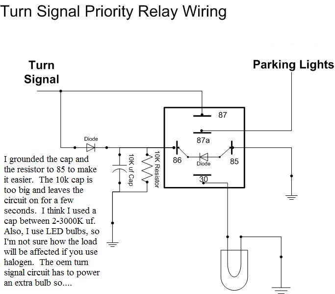
This is what you need to do. The problem with your diagram is that when the turn signal are activated and the light is switching off the relay will revert back to the parking light. So the light will be on at all times pretty much.
http://www.youtube.com/watch?v=qhamYCVm6i4
http://www.yotatech.com/f127/parking...utting-210234/
http://www.youtube.com/watch?v=qhamYCVm6i4
http://www.yotatech.com/f127/parking...utting-210234/
The problem you are speaking of would only happen if the signal for the relay tapped in AFTER the flasher control unit.
The diagram and video that you posted above is another way of doing it - but I don't like that way. There is a slight delay in the light coming on. I don't want that.
I've double checked my diagram and had some other people look at it and it's definitely right.
Good news...my diagram is right, and works perfect, as I suspected. 
I hooked up an LED ring as the test bulb and made a video. The signal flashes exactly the same speed & timing as the front and rear signals. I mounted the L & R relay units right above the flasher control box.
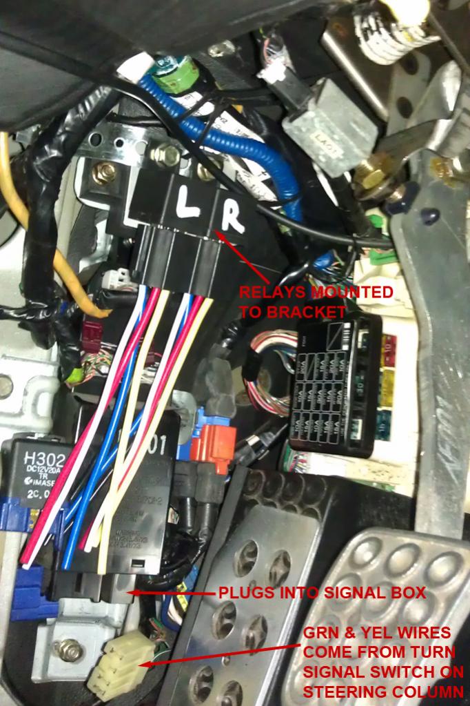
After I mounted them I took a look at the wiring on the harnesses. I decided the wiring was way too small - they look like 12 gauge but they are really only 22 gauge with a lot of insulation. I opted to not use the harnesses and instead make my own wiring with female spade connectors.
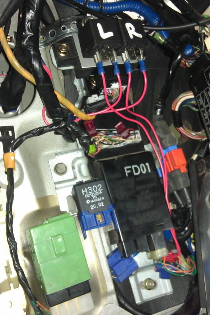
Here's a pic of the relays with the ground terminals attached (#85) and power signal terminals attached (#86):
Here's a video showing the wiring test:
http://www.youtube.com/watch?v=6dPNKSdzvWM
I still need to run the permanent power wires for the parking & signal contacts, and also the wire that will go to the actual side marker. I am waiting on bulb sockets for my side markers to come before anything else so for now the relays will just sit unused where I mounted them.
I hooked up an LED ring as the test bulb and made a video. The signal flashes exactly the same speed & timing as the front and rear signals. I mounted the L & R relay units right above the flasher control box.
After I mounted them I took a look at the wiring on the harnesses. I decided the wiring was way too small - they look like 12 gauge but they are really only 22 gauge with a lot of insulation. I opted to not use the harnesses and instead make my own wiring with female spade connectors.
Here's a pic of the relays with the ground terminals attached (#85) and power signal terminals attached (#86):
Here's a video showing the wiring test:
http://www.youtube.com/watch?v=6dPNKSdzvWM
I still need to run the permanent power wires for the parking & signal contacts, and also the wire that will go to the actual side marker. I am waiting on bulb sockets for my side markers to come before anything else so for now the relays will just sit unused where I mounted them.
Finally got this 100% wired up and the side markers installed.
For parking light power I tapped into the driver's side parking light connector that normally plugs into the side of the stock bumper. I ran it up along (inside) the fender and then passed it though the big rubber grommet that's kind of above the side kidney duct. I ran the power & ground wires for the side markers from the relays and through these same grommets on both sides of the car.
I also wired up the front bumper combo lights so that the outer light (the one with the orange cap inside) is controlled by the respective relay as well.
For the inner lights on the combos, I wired both of them up to the fog light switch since I don't have fogs anymore and I couldn't think of anything else to do with them for the time being. I think I am going to put some super bright white LED bulbs. Don't really need them with the SakeBomb Garage HID projector headlights, but they might look cool. haha
I made a video but it didn't come out well so I'll make another today.
There is a tiny bit of delay on the side markers because they have a normal amber light bulb where as the front turn signals (in the combo lights) have LED bulbs. I've ordered LED bulbs for the side markers though so those should be here soon.
http://youtu.be/T6BHKJMm0u8
Since I didn't have the connector for the bulb socket part, I had to cut it and then solder the wires to the pins:


From a lower angle:

Cheers.
http://youtu.be/T6BHKJMm0u8
Since I didn't have the connector for the bulb socket part, I had to cut it and then solder the wires to the pins:
From a lower angle:
Cheers.

Just thought I would mention that I forgot about something when I came up with this diagram...
The way it's wired according to my diagram the hazard switch won't make the side markers flash.
I checked out the diagram and I think I've figured out how to make this relay setup work so the hazards button makes the side markers flash too (whether the parking lights are on or off).
I'm going to try it out on my owner car and I'll post the updated diagram after I confirm that my idea works.
As I mentioned before, I completely forgot about the Hazard button when I did my first diagram.
The reason the hazards wont function (with the side markers) is because the two 12v relays are not giving the signal to switch over when the hazard button is pressed (because the signal normally comes from the turn signal lever).
I thought I could somehow change the just the wiring but because the hazard switch is only closing a ground (not 12v) it makes it a bit harder. Additionally, the power for L & R relays need to be isolated from each other, otherwise flipping the turn signal switch will activate the flashers on both sides.
To solve this problem I added in a double-pole, single-throw 12v relay. The one I selected is normally used for powered sunroof in a Nissan Altima, and can be picked up for under $20.
Here's the new diagram:
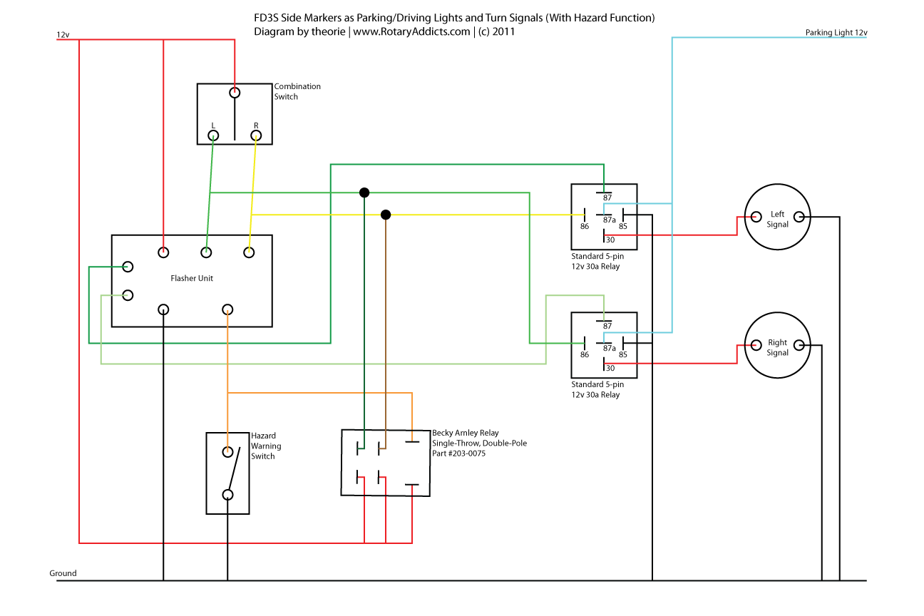
As you can see, the turn signals still function exactly as before, however the added relay will now cause both L & R relays to "switch over" to flashing mode when the hazard button is pressed.
Let me know if anyone sees any problems with this design. Sorry for the crazy diagram - I'm not an electrical engineer so I'm not used to drawing diagrams to any kind of standard. Also, the schematic for the new relay is attached for reference.
The reason the hazards wont function (with the side markers) is because the two 12v relays are not giving the signal to switch over when the hazard button is pressed (because the signal normally comes from the turn signal lever).
I thought I could somehow change the just the wiring but because the hazard switch is only closing a ground (not 12v) it makes it a bit harder. Additionally, the power for L & R relays need to be isolated from each other, otherwise flipping the turn signal switch will activate the flashers on both sides.
To solve this problem I added in a double-pole, single-throw 12v relay. The one I selected is normally used for powered sunroof in a Nissan Altima, and can be picked up for under $20.
Here's the new diagram:
As you can see, the turn signals still function exactly as before, however the added relay will now cause both L & R relays to "switch over" to flashing mode when the hazard button is pressed.
Let me know if anyone sees any problems with this design. Sorry for the crazy diagram - I'm not an electrical engineer so I'm not used to drawing diagrams to any kind of standard. Also, the schematic for the new relay is attached for reference.
