When you click on links to various merchants on this site and make a purchase, this can result in this site earning a commission. Affiliate programs and affiliations include, but are not limited to, the eBay Partner Network.
Hey fellas!
question about some of the wiring, because I'm getting confused
Dpo3 on my harness has 2 wires
In cabin in/outputs has 6 wires
Avi has 4
Manual describes:
"Digital pulsed outputs 1,2,3&4..." with four wires for boost control
"Digital switched inputs 1.." with two wires for launch control
are these wires the in/outputs with 6 wires?
what is dpo3 for?
What is avi for?
And for the grand finale! Lol
How did you guys wire up fuel pump relay control output? Does it go right to that relay under the steering wheel, the black and yellow one?
Sorry if these are super noobish. I'm pretty new to haltech. Been googling my butt off and cant find any good info.
DPO3 should be a single wire (pin A23)
not really understanding your other questions.
Only one DPO is needed for the boost controller, it get power from the other side. (DPO grounds it)
Now this wiring is just an example but shows what the DPO's AVI's and timed inputs can hook up to.
I just used the fuel pump wires to open and close a generic relay. From there you can supply a 12v source to the fuel pump and ground the pump on site.
Thanks bro! Now I just need to figure out how I wanna wire it up.. either back on tge key or toggle switch...
would you also know about those in cabin in/outputs? I'm thinking those are additional dpos and dsi, and the wire bundle marked dpo3 is just the main dpo.
Just trying to be careful because I don't wanna fry my haltech.... or my car...lol
So DPOs are basically a switched ground. You can change what activates the DPOs within the haltech software. For example, Say you hook DPO1 to a relay controlling a cooling fan. You would set DPO1 to "Coolant Switch" in the software, and it will give you an option to set the temperature at which it kicks on. Theres lots of options you can choose to activate the switch. Each DPO is a seperate switch. Trying to explain this the best I can this early in the morning.
You can use the 12v supplied by the DPO harness for the other side of the relay.
Now the DSI is basically a 5v on/off switch. When that wire sees 5v, it triggers whatever you have it set at within the ECU. Do not ever put more than 5v to any 5v input. You will fry the 5v regulator. Ask me how I know.
AVI is a 0v - 5v is for sensors. most sensors like widebands or coolant temp sensors put out values from 0v to 5v. The ECU converts these values into AFR or temperature or whatever youre using it for. For Example, if youre using a wideband that has a range from 7.4AFR to 22AFR, 0v would be 7.4AFR, 5v would be 22AFR, and 2.5v would be somewhere in between like 14.7AFR.
I hope this all makes sense. Anyone please correct me if im wrong.
Last edited by F�hrerT�ner; Nov 8, 2016 at 08:43 AM.
So for wiring up the boost solenoid. I'd use:
Grey/red wire switched 12v supply and
dpo2
And after some reading, use for tach:
Dpo1 using the stock coil signal wire.. right? Lol
im trying to get the old tach to work
avi to wideband O2
Only new question is, for incorporating the launch anti lag switch. I was going to wire to the stock clutch switch. But where would I get a 5v signal/source?
Sorry for all these questions. I'm reading as I'm posting and working on the harness as I go. I really thought this harness was going to be more plug and play than it is lol. Live and learn. Again. Thanks for all the help!
Oh! This just came to mind! Do I need an additional map sensor? Or is the one one the ecu that would go to manifold sufficient?
So for wiring up the boost solenoid. I'd use:
Grey/red wire switched 12v supply and
dpo2
The DPOs are universal. You dont have to use DPO1 for boost control only. But yeah that seems right. May want to get a 2nd opinion, i use an external controller.
And after some reading, use for tach:
Dpo1 using the stock coil signal wire.. right? Lol
im trying to get the old tach to work
should work, theres specific settings you need for the duty cycle, youll have to look that up. Pulses should be at 4.
avi to wideband O2
Only new question is, for incorporating the launch anti lag switch. I was going to wire to the stock clutch switch. But where would I get a 5v signal/source?
youll have to ask someone else on this one.
Oh! This just came to mind! Do I need an additional map sensor? Or is the one one the ecu that would go to manifold sufficient?
The internal map sensor is good for 36 psi
Last edited by F�hrerT�ner; Nov 8, 2016 at 12:19 PM.
DPOs switch to ground. So, for a given device, you'll usually pair a DPO with a switched 12V feed. For example, a boost control solenoid would get 12V and a DPO. Same for an idle control valve. Those two can be controlled directly by the ECU. A fan would need a relay, so the DPO would be connected to terminal 85 of a relay to switch it on/off.
DPO 1 is the only DPO with the correct pull-up (12v) built in to control the tach. So it needs to be dedicated to the run the tach. If you have an FC and will keep the stock trailing coil, which runs the tach, or plan to use a digital CAN based dash, you could use DPO 1 for something else. It's always a good idea though to keep it reserved to run a tach, just in case, unless you are completely out of other options.
DPI are pulsed digitial inputs. Use these for flex fuel and whee speed primarily. Can also be used for switched inputs for things like two step, AC request, etc. Generally, when using as a switched input, you'll connect one side of the switch to signal ground and the other side to the DPI. Inputs are 12V tolerant.
DSI is dedicated digital switched input. Similar to the DPI but can't be used for pulsed inputs like flex fuel and wheel speed. Can only be used as a switched input. DSI will generally change states faster than the DPI so this works well for 2-step, specifically.
AVI are analog inputs. They're generally paired with 0-5V sensors for temp and pressure readings. Can also be used as switched inputs. Two wire temp sensors will require a 1k ohm pull up resistor to 5V ref with the Sport and Sprint ECUs. Elites have a built in selectable pull up.
Tach is 12V pull up, 50% duty, 4 pulses.
Internal MAP sensor on Sport and Sprint is 2.5 bar absolute. So 22 psi max. Elite is 3 bar.
I encourage you to open the software and hit F1. This brings up the manual included in the software. There's most all the information you'll need to properly connect everything in there.
36.75 psia, yes. but 22.05 psig, which is what you're trying to say. It's the difference between absolute and gauge pressure. All MAP sensors are rated in absolute pressure. You're talking gauge pressure. Look it up.
Interesting. So basically you subtract whatever the atmospheric pressure is at your specific elevation, and that would give you psig. The more you know....
Really great info guys!! Thanks alot. Sorry it took a while to reply, to be honest been tied up with a hospital visit. I'll get back to it here shortly with some results. Thanks again. Club saves the day again.
Back with more . Didn't want to make a new post for more of my noob questions lol
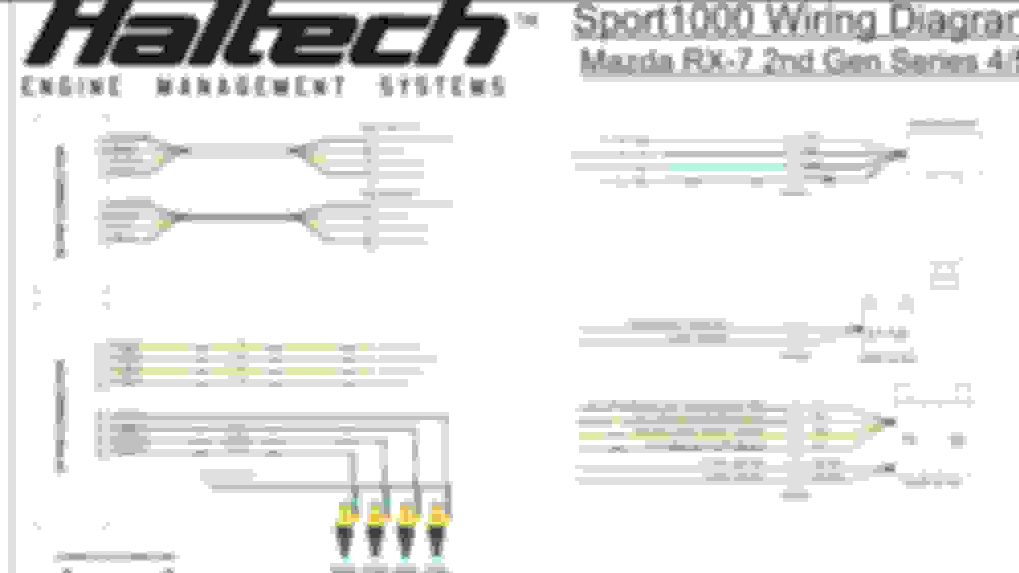
Concerning the ignition coils. Been researching my *** off and I have this info:
S4fc with stock coils will get "tuned" as distributor.
Haltech wires . Fc wires
Ign1. To. Leading 1&2
Ign2. To. Trailing 1&2
Ign3. To. Toggle.....
I imagine both black wires from haltech are just chassis grounds. But not sure how haltech yellow and red connect to the stock coils. And how/what the hell is toggle connected? I read on one post that it goes to trailing. Just not sure how.
If someone were nice enough to draw a kindergarten picture for my crayon eating self that'd be great lol.
Minus that I've got almost everything else figured out or done
For the ground wires, Ludwig correct me if im wrong, but the sensor ground should go to the negative battery terminal, and the ECU ground should go to the stock ground location on the tranny (well thats where i put it anyways).
Ya, I've seen that one a few times. Only issue is, those colors don't match my harness side. I have four sets of four wires. Two blacks yellow and red
so maybe I'm looking at that diagram you put up wrong. But I don't want to wire it up wrong guessing.
Ya, I've seen that one a few times. Only issue is, those colors don't match my harness side. I have four sets of four wires. Two blacks yellow and red
so maybe I'm looking at that diagram you put up wrong. But I don't want to wire it up wrong guessing.
Black yellow are 12v for sure.
I just remembered something is wrong with this diagram. Standby.
I think I left out info. Actually Im Sure I did. . At the end of haltech ignition I have flying lead. I'll just have to trace out what those wires correspond to.
but as of now. I think I understand this:
Haltech yellow/black=ign1 to lead pink
Haltech yellow/red=ign2 to trail pink
Haltech yellow/Oran=ign3 to trail white
Haltech yellow/green=ign4 *not used*
Haltech pink=12v switch to cdi box *not used*
Haltech black= ground.. I assume body
Haltech red/yellow=12v frm relay to... L&T coils light green wires??
Large gauge black goes to chassis ground. Not real important where as long as it's a good connection. Clean the body of paint with a sanding disc if you go to the body. Large black/white goes directly to battery negative. Don't take a short cut on this one and think chassis ground is good enough.
Red/yellow is coil 12V+ plus. Connect as shown above. Their colors may not be right. Reference the diagram below for correct connection.
Pink wire is switched 12V+ ignition. This needs to connect to a switched source that is on when the key is in the run AND start position. This is the turn on signal for the ECU.
I think I got the ignition all wired up correctly. And now I'm nearing the end, but I'm running into what I think is another issue. Before installing the haltech harness, I pulled the dash to eliminate the engine/ECU side of the stock harness. Now when I do system tests to make sure nothing is catching on fire heater/ac fan won't work and starter won't engage or do anything. Should I have left the stock harness inline with the new haltech harness?
I'm out working on it now. If I find any other issues I'll post as soon as I can. Trying to get this done or close to it before surgery tomorrow :/


 . Didn't want to make a new post for more of my noob questions lol