
Haltech Has anybody got the haltech CL boost controller to work .... well?

Thread Starter
Joined: Feb 2006
Posts: 2,897
Likes: 2
From: Renton/Bellevue/Seattle WA
Has anybody got the haltech CL boost controller to work .... well?
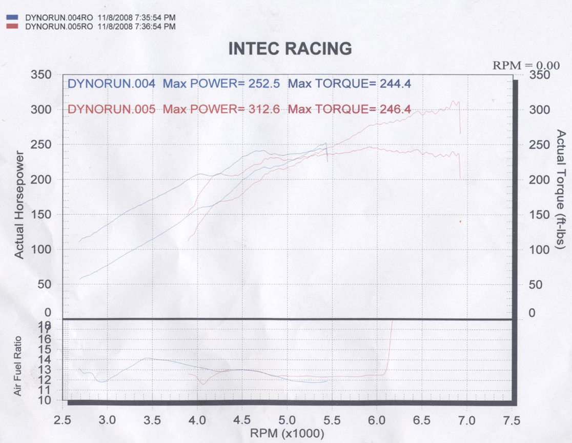
Hi all. Just wondering if anybody had had any success making the haltech closed loop boost controller work? I have fiddled with it for .... ohhh ... 60+ hours, and it seems to ... well suck. I had a dyno this last weekend and Everything went fine at 9.4 psi, but then when I turn it up one more tick to like 9.9 target boost I get what you see below.
(First run: 9.4 psi. then second: 9.9 going 9.9, 5, 9.9, 5 for NO reason. It was going 100, 0, 100, 0 duty cycle.)

I have to go out for a drive on the freeway for another hour to get it tuned so it worked at 11 psi and then did my last dyno run. Going through all the "features" in my head like gear specific boost levels and such just seem like there is NO way someone could get that to work well. Even though I got mine to work and control boost, it controlled it like CRAP, massive drops in boost and such. Maybe I am missing something major here? When ever I change target boost I have to change start duty cycle, and where it starts before target, and then it only works well in that gear in those conditions. If I set it so it works ok in 3rd and then do a second gear pull, it's all screwed up. Does anybody else have the same experiences as me?
(You can still see the massive torque drop after it reaches 11 psi, then falls down to like 9, then back up to 11 SLOWLY)
Thanks.
(First run: 9.4 psi. then second: 9.9 going 9.9, 5, 9.9, 5 for NO reason. It was going 100, 0, 100, 0 duty cycle.)
I have to go out for a drive on the freeway for another hour to get it tuned so it worked at 11 psi and then did my last dyno run. Going through all the "features" in my head like gear specific boost levels and such just seem like there is NO way someone could get that to work well. Even though I got mine to work and control boost, it controlled it like CRAP, massive drops in boost and such. Maybe I am missing something major here? When ever I change target boost I have to change start duty cycle, and where it starts before target, and then it only works well in that gear in those conditions. If I set it so it works ok in 3rd and then do a second gear pull, it's all screwed up. Does anybody else have the same experiences as me?
(You can still see the massive torque drop after it reaches 11 psi, then falls down to like 9, then back up to 11 SLOWLY)
Thanks.
Thread Starter
Joined: Feb 2006
Posts: 2,897
Likes: 2
From: Renton/Bellevue/Seattle WA
At first I used trail and error, then after that I used the non closed loop boost control till I found a somewhat steady one with that. Then I went back to trail and error because it changed every time I changed my target boost .5 psi. O.o
I have tried every pid setting from 0,0,0, to 100,100,0. I have documented and took a screen shot of every log and change in 5 point increments.
I have tried every pid setting from 0,0,0, to 100,100,0. I have documented and took a screen shot of every log and change in 5 point increments.
Set your PIDs to 3,3,0 and put it back to closed loop boost control. Log your A/D output duty cycle and you should see what duty cycle it takes to get stable boost. Then plug that duty in as your start duty cycle.
Good luck.
Good luck.
Thread Starter
Joined: Feb 2006
Posts: 2,897
Likes: 2
From: Renton/Bellevue/Seattle WA
but that stable boost is going to change with every slight target boost change, and or gear change (basically how fast it comes on). What will be stable for target boost 9 in 4th gear, will not be for 11 target psi in 2nd gear.
If you plan on running multiple boost settings use the "start duty map" feature.
Trending Topics
'Tuna'
Joined: Feb 2001
Posts: 4,637
Likes: 3
From: Miami,Fl,USA

Have you actually tried learning how to use the basic open loop boost control?
How about just learning to use the basic boost controller at first. Once you got that figured out and learnt your dutycycle % vs boost then you should move on.
Why is it everyone is always trying to walk before they learn to creep!

FYI. I have perfect boost control on every application I've used it on not to mention boost-by-gear on a certain one.

The way Haltech has their closed loop boost control setup is basically the same many of the other top ECU brands have it also.
They just nailed the gear ratio/speed correct vs say what Amateur Engine Managemant did with their setup!
Last edited by crispeed; Nov 12, 2008 at 01:18 AM.
'Tuna'
Joined: Feb 2001
Posts: 4,637
Likes: 3
From: Miami,Fl,USA
From the Haltech manual latest revision.
The wastegate of a turbo is operated when the manifold pressure acting on the diaphragm within the
wastegate actuator overcomes the return spring allowing exhaust gas to bypass the turbine. With
electronic boost control, the object is to use a pulsating solenoid to bleed off the manifold pressure signal
seen by the waste gate unit so that it can see only a fraction of the manifold pressure. The solenoid
operates at constant frequency and the duty cycle is altered to control the drop in pressure signal through
the device.
The turbo wastegate map allows boost to be increased over the standard boost that the turbo and
wastegate combination provides. The turbo wastegate solenoid will only activate when it sees positive
manifold pressure.
To setup the wastegate map, it will be necessary to iterate through several trial and error runs to ensure
safe boost conditions. Use the following steps as a guide to setting up your Turbo Wastegate map:
Always start with small duty cycle settings and increase until the desired boost level is reached. Start with
a flat map (same duty at all loads and speeds) at low duty settings and drive the car noting any increase in
boost level. Watch you�re A/F ratios very carefully when increasing boost for the first time as this part of
the map will not have been tested if this engine has not been mapped at this boost level.
You can setup a flat map easily by selecting all bars then using �v� to set a fixed value. Then use copy and
paste to copy this range to all other ranges to achieve the flat map shape. Make sure you run the engine
at the engine load and RPM at which maximum boost is typically reached.
Increase the duty of all the bars of the map and test-drive the engine once more. Again, make sure that
your fuel maps are adjusted to ensure safe A/F ratios at every step. Repeat until the desired maximum
boost is reached and not the duty cycle of the bars.
Now that you have set the maximum boost to the desired boost pressure, you can increase the duty cycle
at all engine speeds and loads at which the boost pressure is below the desired maximum boost. This will
help the engine reach its desired boost pressure quicker. This will alter the fuel requirements at these
engine loads and speeds so watch you A/F ratios carefully and adjust your fuel maps to compensate if
required.
Closed Loop Boost Control
Closed loop boost control is a method of controlling boost where the difference between the target
boost level and the current boost level is taken as an input to the controller and used to adjust the
output, the duty cycle of the solenoid, accordingly. An advantage of closed loop boost control is it is
more resilient to outside factors not part of the controller like air temperature making this form of control
more consistent than the wastegate map.
Settings
� TWG Frequency - Frequency (Hz) that the waste gate solenoid will run at. A Typical value for the
Haltech waste gate solenoid is a frequency of 20 � 30 Hz.
� Start Duty Cycle - This is the duty cycle that the waste gate will go to when closed loop boost
control begins. This duty cycle should cause the boost to read somewhere below the target boost
level. If this value is too high then the boost will overshoot the target boost level before it returns to
the target. If too low the boost may dip down a bit before being controlled.
� Control Point Before Target - An offset in kPa or PSI from the target boost level at which boost
control will begin This value maybe increased for applications where boost is made extremely quick
and to give the controller more time to react. E.G. if the boost target is 120 kPa and the �Control Point
Before Target� is set to 20 kPa then boost control will begin at 100 kPa. Default 20 kPa or 3 PSI.
� Delay till Boost Control - Once the boost controller has reached the �Control Point Before Target� it
will hold at the start duty cycle for this amount of time before controlling boost. Default 0.5 sec.
� Start Duty By Map - When checked it will ignore the �Start Duty Cycle� value above and base it off
the Start Duty Map.
� Use Boost Map 2 - Check this box to use �Closed Loop Boost Target Map2� as the target map.
� Start Duty Map - Output Start Duty Cycle vs. Target Boost Level. This map can be used when the
target boost level that the boost controller is aiming for changes each time it goes to control boost.
Such situations where this map is needed are when using the closed loop boost control trim or gear
boost correction.
� Boost Target Map - Output Target Boost vs. RPM. Allow the setting of different target boost levels
over the range of RPM.
� Proportional/Integral/Derivative - Values are used to alter the gains and response of the controller.
Derivative should remain at zero.
'Tuna'
Joined: Feb 2001
Posts: 4,637
Likes: 3
From: Miami,Fl,USA
Boost By Gear
Here's something not explained in the manual.
The theory behind gear boost control is to have varying boost levels depending on gear position.
In the gear ratio chart the first column is for speed. There you enter for each gear what the mph would be at 1000rpm. For example in 1st gear with the motor/engine at 1000rpm let's say the speed would be 10mph. Then in 2nd gear at 1000rpm the speed would be 20mph etc. You basically set the speed for each gear position based on the motor being at 1000rpm in every gear. The first time I did this the car was on a lift so it was easy for me. You could do the same on a dyno or the street if you're carefull.
Next column over would be for the wastegate dutycycle % you got when setting up the boost control in 'open loop mode' Basically you have a certain duty % vs boost level. For example you may have 10 psi at 20%, 15psi at 25%, 20psi at 30% etc.
So if you want 10 psi in 1st gear you enter 20%, 15psi in 2nd gear you enter 25% etc.
The third and final column is where you enter the actual boost correction level. This is where it gets a little tricky to describe.
Each gear position represent a percentage(%) value of the max boost. Let say in 4th gear you're running max boost then you enter 0.
In 3rd gear you want to run 5 psi less then you enter -5, in 2nd gear you want 10 psi less you enter -10.
Hope this helps a liitle.
Thread Starter
Joined: Feb 2006
Posts: 2,897
Likes: 2
From: Renton/Bellevue/Seattle WA
No, so I can set better duty cycle points instead it being linear between 5.44, 10.88, and 16.32 psi. It's great though that I can have it control 87 psi, but I don't see myself doing that any time soon. I would like a little higher definition at the lower psi.
And I will be the first to point out I have no clue what I am doing, but I am willing to learn. I just knew I was missing something major. I am excited to fiddle with this. Hopefully (doubtfully) I can save myself some money by getting this reliable, and not having to buy the ams-500.
I would like a little higher definition at the lower psi.And I will be the first to point out I have no clue what I am doing, but I am willing to learn. I just knew I was missing something major. I am excited to fiddle with this. Hopefully (doubtfully) I can save myself some money by getting this reliable, and not having to buy the ams-500.
Last edited by TweakGames; Nov 12, 2008 at 02:53 AM.
