
Haltech aem smart coils with e11v2

Thread Starter
Full Member
Joined: Oct 2007
Posts: 127
Likes: 0
From: Florida
aem smart coils with e11v2
Im installing these babies on my 3gen. Im a little confused with the wiring
A- signal from haltech
B - ?? Is this another ground?
C- ground
D-ground
E- 12v from haltech
Is A correct?, is B just a ground? All your help is apreciated.
Please feel free to correct me.
A- signal from haltech
B - ?? Is this another ground?
C- ground
D-ground
E- 12v from haltech
Is A correct?, is B just a ground? All your help is apreciated.
Please feel free to correct me.


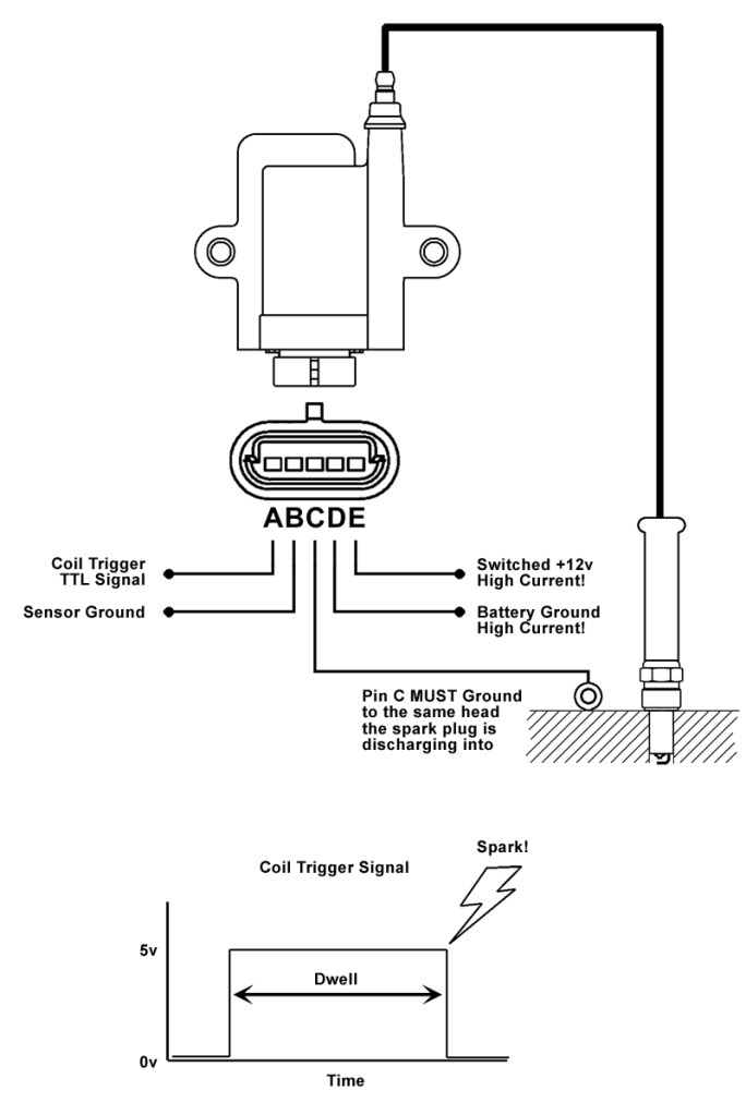
A- TTL signal from ECU (IGN1, IGN2, etc.)
B - Ground
C - Ground
D - Ground
E - 12V+
B, C, D can be ganged together on a single lug. The multiple grounds are for misfire detection that your ECU does not employ. So ground them all. Either to the rotor housing or battery negative. I usually use 20 g wire at the connector and then gang the three wires into a minimum of 16 g for each coil.
E is battery positive. This needs to connect directly to the battery through a fuse and relay. Use a minimum of 14 g for the four coils.
Trending Topics
Thread Starter
Full Member
Joined: Oct 2007
Posts: 127
Likes: 0
From: Florida
chris, i got them installed like u said and they work like a charm. Got in touch with the tuner u recomended which happens to be Chris also. He got the car running smooth andready for fine tuning . Thanks to both Chris'es.
http://static.photobucket.com/player.../VIDEO0017.mp4
http://static.photobucket.com/player.../VIDEO0017.mp4

Originally Posted by Kalle
I have installed my coils in accordance with this thread. However the ignition seems to break up around 7000rpm. Running direct fire and 2.8ms dwell. Any ideas?
Do not gang all grounds together. B+ and power ground shall go directly to the battery, even if the battery is relocated to the interior.
The secondary return must ground to the rotor housing it's firing into for the shortest loop area. Not everyone individually segregates the two housing returns, but that is the ideal way to do it.
The logic ground is supposed to go to sensor ground (I have personally discussed this with Neil, the designer of the coils), but most people and professional harness offerings join this with the secondary return and it usually works alright.
Last edited by DC5Daniel; Apr 24, 2020 at 02:54 PM.

Full Member
Joined: Jan 2006
Posts: 173
Likes: 13
From: VA
Thank you Daniel! Right now I got all 3 grounds from each coil wired to one point on the chassis. To this point I also have a ground wire that goes all the way from the battery (its in the trunk), this ground wire makes a short stop in the footwell where the Haltech is also grounded to. Would this be considered "directly to the battery" or do I need a completely uninterrupted wire that does not have contact with the chassis? Also, to the chassis grounding point I have one more ground wire that comes from the center housing. In my mind, this cris-crossing of ground wires should have had me covered.
So, the solution for me would be to run secondary return L1&T1 ground to No1 housing and L2&T2 ground to No1 housing?
Could it also be a dwell-time issue?
Cheers
So, the solution for me would be to run secondary return L1&T1 ground to No1 housing and L2&T2 ground to No1 housing?
Could it also be a dwell-time issue?
Cheers
Originally Posted by Kalle
Thank you Daniel! Right now I got all 3 grounds from each coil wired to one point on the chassis. To this point I also have a ground wire that goes all the way from the battery (its in the trunk), this ground wire makes a short stop in the footwell where the Haltech is also grounded to. Would this be considered "directly to the battery" or do I need a completely uninterrupted wire that does not have contact with the chassis? Also, to the chassis grounding point I have one more ground wire that comes from the center housing. In my mind, this cris-crossing of ground wires should have had me covered.
So, the solution for me would be to run secondary return L1&T1 ground to No1 housing and L2&T2 ground to No1 housing?
Could it also be a dwell-time issue?
Cheers
So, the solution for me would be to run secondary return L1&T1 ground to No1 housing and L2&T2 ground to No1 housing?
Could it also be a dwell-time issue?
Cheers
https://adaptronicecu.com/blogs/modu...grounding-tips
To directly answer your question above, I would advise you to undo all the ganged grounds, and run your power ground directly to the battery (and only the battery) with a sufficient gauge wire. To give you some perspective on what that would be, 12-14awg is typically acceptable for a bin mounted battery. You're carrying up to ~20A of current all the way from the trunk, round trip
 so same applies to your B+.
Despite the success a lot have with these coils, a lot of people struggle with this symptom (myself included). Usually, not always, wiring these coils properly or "better" than they were before will remedy the issue, assuming it's not something tune related.
Last edited by DC5Daniel; Apr 24, 2020 at 03:56 PM.
Originally Posted by Kalle
Wow what a jungle! Thank you so much for the help.
One more question. What do you mean with B+ ground? Is that sensor ground? What is sensor ground exactly?
One more question. What do you mean with B+ ground? Is that sensor ground? What is sensor ground exactly?
Sensor ground at its most basic form, is exactly what it sounds like; a return path dedicated for sensors. The concept of sensor ground is that it's a low current and low noise return path that serves as a reference for the sensor to ECU interface. The reason it is "required" by the coil designer is because he doesn't want the inherent ground offset through the main ECU ground on the engine to interfere with the logic threshold of the coil trigger. Again, most people get away with this just fine and that's the accepted practice in this community, so take from that what you will.
Mazda actually connected power ground and sensor grounds together externally in the harnesses on earlier cars (S4 FC and NA Miata), only to segregate them in later versions. As an automotive electrical design engineer myself, I'm sure this was a countermeasure to fix an issue discovered late in the design, and was later revised when the original issue was resolved.
So in closing, there is a reason why the coil has 3 discrete ground circuits, they all serve different purposes and by design have different installation requirements for optimal performance. What people can get away with is different from how it "should" be done. You decide where to draw to the line.
Last edited by DC5Daniel; Apr 25, 2020 at 07:26 AM.
This is absolutely correct.
Common problem and usually related to grounding strategy (which has changed in the 8 years since this thread was active). If you read any of the other threads regarding these coils you will find a lot of information. I've also spoken to Chris Ludwig and he changed his strategy since his post here (don't recall if I've seen him post otherwise, but I have communicated with him on the topic since at least 2015).
Do not gang all grounds together. B+ and power ground shall go directly to the battery, even if the battery is relocated to the interior.
The secondary return must ground to the rotor housing it's firing into for the shortest loop area. Not everyone individually segregates the two housing returns, but that is the ideal way to do it.
The logic ground is supposed to go to sensor ground (I have personally discussed this with Neil, the designer of the coils), but most people and professional harness offerings join this with the secondary return and it usually works alright.

Junior Member
Joined: Mar 2016
Posts: 22
Likes: 2
From: Okinawa
Man I hope someone on here can help me out. I have been having some ignition issues with my ign1a coils, that no one can seem to figure out including myself. I have had a sakebomb harness, and then modified it, like the way below since they originally had b/c grounded together and I thought this was the issue. Nope. And now the coils will randomly overheat and literally melt, with just the key in the on position. I have wired them up following the specific directions from aem.
A is from haltech ignition output
B is from haltech sensor ground (all 4)
C is on each rotor housing as it should be (2 each 18awg spliced to a 12awg wire grounded by terminal to housing)
D is wired directly to battery ground with 12 gauge wire
E is from battery positive (12 gauge), which goes to a relay (pin 30) pin 85 on relay is to battery ground, pin 86 comes off 12v switched ign (off spade connector from fuse box driver side) and then of course pin 87 is 12 gauge spliced to x4 18awg wires that go out to each ignition coil.
Grounds on the car, battery is in bins in rear
negative battery cable goes to bare chassis ground
Negative 2awg runs from rear of negative, to front of car, grounded to chassis
Alternator grounded to same front point on chassis
Engine/trans grounded to same front point on chassis.
So have 0awg from negative grounded in the trunk. 2awg negative battery to front frame, with alternator case grounded, engine, and transmission.
This has been a on going issue that occurred out of the blue. Thought it was a bad coil, but no luck. Swapped, with new coils. Then it happened again. And it is just random on which coil it is. It�s never a constant coil. This has been happening for going on a year now. I just rebuilt my motor. Re did the wiring. Only thing I did use was the same sakebomb connectors. I do have 6 of the new aem ign1a plugs I was considering trying to fully re wire and see. But I am at a loss. I was hoping you had some in-site/could possibly help. Before I was running a adaptronic modular. Thought it was the ecu that was the problem. Swapped to haltech elite 2500. Same issue. I am at a loss. I�ve been through the wiring, it all checks out fine unless I�m missing something. I have even tried the whole stacking grounds for pin b/c/d and same issue no matter what configuration. I have tried 3 different sets of ignition coils. I�m sick of frying coils and am lost at this point. no wiring is going to the oem chassis anymore. Haltech elite trigger outputs go to the ignition coils. Then of course it�s just switched ignition that triggers the relay to allow the 12vdc to go to the coils on pin E. It is fused at the battery as well with a 20amp fuse that hasn�t blown. So I�m at a loss. Any information will be greatly appreciated. I�m lost at this point and just want to have my fd running.
Funny enough, I ran into the same issue this week with my haltech after burning through a few coils myself. I was talking to another ecu mfr in passing and they recommended taking a look at the +b to the coils. How it was explained to me is that if the coils are left too long with 12v constant and no discharge, they will store that charge until they melt themselves. One way to avoid this is using a rpm activated output to the relay powering the coils that activates at 50 or so rpm. This way the coils are not left getting a steady stream of 12v with nothing to send it to. I tried this strategy with success on a different ecu and will look at doing the same with my haltech unless theres some better input from guys with more expertise.
Cheers

Junior Member
Joined: Mar 2025
Posts: 5
Likes: 0
Good day everyone.
I know this is an old thread, but what i would like to find out with the new Haltech R3 with the HCO connection which give 25A on the power line, do you still need a relay and fuse for the IGN-1A Coils?
Kind Regards
I know this is an old thread, but what i would like to find out with the new Haltech R3 with the HCO connection which give 25A on the power line, do you still need a relay and fuse for the IGN-1A Coils?
Kind Regards