When you click on links to various merchants on this site and make a purchase, this can result in this site earning a commission. Affiliate programs and affiliations include, but are not limited to, the eBay Partner Network.
I have block the oem oil filter position (I have relocate my oil filter).
Can I use a line(an 8 fitting) from the relocation filter adaptor to front iron?
Another way you can increase oil flow to the rotor bearings is to limit oil cooling flow by putting in the Mazdacomp restricted oil cooling jets or the Webber jet mod to restrict flow.
Stock
Restricted
Are these the Mazda Competition oil cooling jets you were talking about? If so what size are the normal cooling jets?
I dont have a great way to measure for you, so I stuck the shanks of drill bits into the stock and Mazda Comp rotor cooling jets.
Stock jet was ~2.5mm or 0.098"
Mazda Comp jet 8553-11-411 was ~2mm or 0.079"
The Mazda Comp jet 2mm corresponds to Weber 200 jet recommended by Racing Beat for pressing into the rear of stock 2.5mm jets for NA race cars and Racing Beat recommends 220 Weber jets (2.2mm) for Turbo race applications.
I also looked over old threads by rotary guru Lynn E. Hannover and my measurements correspond exactly to what he wrote then.
I have no idea where the 0.200 size comes from in Mazda Trix description. Who measures in 10ths of MMs? Who doesnt include units with measurements? They do include the Mazda SKU now so you dont have to reconfigure the MazdaTrix part numbers anymore.
its not funny, but worth pointing out that the stock jet is bigger, but doesn't flow as much because its got a check ball and spring.
so the competition mod is essentially to get rid of that, but 2.5 mm is too big, so they went smaller.
the ball and spring keep it from oiling the rotor at low RPM, which is why the race stuff isn't recommended in a street car, your idle oil pressure will be really low
No, the stock jet is bigger and flows more oil into the rotor.
The oil flows through the square openings around the check ball with no restriction when the check ***** are extended by centripedal force.
The whole point of the Mazda Comp rotor jets is to LIMIT oil flow out into the rotors so there is more oil pressure for the rotor bearings.
Eliminating the check ***** is just a race reliability mod like locking the distributor and will have some benefit in regards to heatsoaking rotors in the pits.
The Mazda Comp jets do flow more oil than the stock jets with the check ***** closed off at low rpm- that is why oil pressure is lower at idle with Mazda Comp jets.
______________
Lynn E. Hanover , 05-03-2004 08:47 PM
Fabricator
Quote:
Originally Posted by BDC' date='Feb 8 2004, 03:46 PM The outlet on the stock jet is larger by about 1.5 to 2 times. I think just removing the ball and spring and using the jet alone would make the oil pressure at idle drop to nearly zip. That's my theory on it, atleast.
B
The stock jet hole is in excess of .100" the 200 weber jet is smaller than that. So the recomendation in the Racing Beat book is suggesting that you reduce oil flow to the rotors for high power applications. It is not well explained in the Racing Beat book.
However,
This is a racing only change that will get you poor oil pressure at idle and just off idle. The object is to control the amount of oil going to the rotors at high speed.
If you add the 115 pound pressure relief valve for racing, once the oil is hot, you will be adding oil to the rotors in buckets per second quantities, with the stock setup. For turbo cars, rotor temperature is a bigger problem, but even then if you are not running flat out across Nevada at night with all of your ECM gear running, then what is your problem?
The added amounts of oil is of no value at all to the rotors, and you want a bunch more of that oil to be going to the bearings to move out superheated oil lest the bearings start to loose overlay. Rotor cooling in turbos is to prevent detonation.
Not a problem in NA engines (OK if you climb Pikes Peak in 5th gear it's a problem)
but for the most part not a problem.
So why do that?
If you have the good pump, and shim the front relief so it cannot open, and add the 115 pound rear relief then your full throttle oil pressure will be 115 pounds hot. You could squirt hot oil through the stock jet (over .100") over your house. And there are two of those holes in your oil system. The weber jets cut down these two (leaks) to something reasonable, like enough to cool 4 rotors. But it ain't for the street. At 60 to 80 pounds of oil pressure the flow through the stock jet (the hole in the screw) is much reduced. And therefore ideal for street use.
The oil hole in the rotor bearing throw has a slight centrifugal force advantage over the oil jet, so in theory, the pressure at the rotor bearing is higher even though the is no restriction at all in front of the cooling jet hole.
At any rate (pun) the ball and spring offer no restriction to oil flow, because the oil goes through the square opening behind the spring.
If you want to do this anyway, you can braze the stock jet shut and redrill it to match a .200 Weber jet.
So there you have it. The jets restrict oil flow to the rotors when high oil pressure is used. Weber main jets fit the taper at the bottom of the jet well better than the Weber air correctors, but it matters not what you use. If you do this you need more than stock oil pressure. There is no need to glue the jet into the holder. It cannot go anywhere, and if the jet screw comes out, the jet will definitely not be your problem. They used to take a three corner punch, and stake a bit of crank material into the screw driver slot in addition to the Locktite or simular on the threads.
If you have done this and have not added the high pressure relief valve, there is no shame in that. There is also not much oil pressure at idle. If you don't run it real hard, it won't matter, and the oil pressure comes up with RPM, so it won't hurt you there. But don't add the high pressure relief valve thinking that it will cure the low idle oil pressure. It will not. Those oil holes are now open all of the time, and at idle there is just not much oil flow, thus no oil pressure.
On the other hand, the bearings are huge and just need a few drops of oil at idle to survive. So tape over the bottom of the range on the gage and forget about it.
so just bumping this, and without going into the details on the why part of it, which is inconsequential to the inquiry.
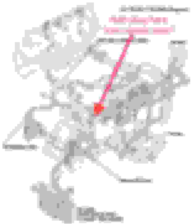
If someone wanted to physically seal or block off the oil galley flow to the dowel position in the REW front iron, is it feasible to simply press or drill/tap/thread a plug there from the dowel hole opening side?
maybe it’s not clear what I’m asking; I’m referring to internally blocking the oil galley to the dowel pin. Most people using a solid dowel would just rely on the dowel and O-ring there to block it. I actually want to physically block off the oil galley there rather than rely on the dowel/O-ring. If nobody has the answer then I’ll likely have it myself tomorrow when the new front iron arrives. Likely nobody else ever cared enough to bother with it and just let the solid dowel serve that purpose instead.
.
it's still going to be pressurized if blocking the front, the flow comes from the oil filter down into the galley, why not block it at the rear iron instead?
that end is easily addressed. So no need to either mention or discuss it.
However, I inspected and assessed a new front iron today. There’s only maybe 1/4” between the dowel opening end-stop and the oil galley diameter going to the front stationary bearing. Thats not a lot of meat to work with, but we only need to stop flow and the pressure relative to the area won’t require much thickness to hold against the resulting force upon it.
looking in the dowel hole from the rotor housing side.
It appears that if it was tapped and a threaded plug with thread sealer was used there, that the opening going straight through to the stationary bearing can be expanded in the other directions to provide an equivalent flow entrance area if the plug protruded through some to block the side into the dowel entrance. Or that the plug face itself could be ground into the main galley opening shape, but that’s going to depend on how deep the allen hex hole is relative to the thickness.
Otherwise it may require either using a thicker plug and machining down the excess on the dowel side to be flush with the dowel opening end-stop, or applying the same process using a plug that has an external hex/square protrusion for tightening it down. My assessment is that it can be accomplished by a reasonably skilled machinist.
ps: I love the smell of fresh cosmoline in the morning
.
i.e. recently manufactured irons arriving from Japan.
.
bumping this to ask if anyones knows or can verify the solid 1pc dowel length for a 13B REW?
just measuring the total length on the oil galley dowel position with machined ends, I’m coming up with 234mm (12mm+80mm+50mm+80mm+12mm) as the total available length. The other galley-less dowel position without the machined ends seems to accept a longer total length.
As far as I’m aware, everyone is using the same single dowel length in both ends though. I’m just not sure what that length is though. Ran a bunch of searches and haven’t found it mentioned or discussed.
Obviously 12A, 20B, 26B etc. are different lengths, but haven’t found any lengths ever listed. Kind of like looking for the proverbial needle in the haystack given how old this forum is. Assuming anyone ever did list them.
bumping this to ask if anyones knows or can verify the solid 1pc dowel length for a 13B REW?
just measuring the total length on the oil galley dowel position with machined ends, I�m coming up with 234mm (12mm+80mm+50mm+80mm+12mm) as the total available length. The other galley-less dowel position without the machined ends seems to accept a longer total length.
As far as I�m aware, everyone is using the same single dowel length in both ends though. I�m just not sure what that length is though. Ran a bunch of searches and haven�t found it mentioned or discussed.
Obviously 12A, 20B, 26B etc. are different lengths, but haven�t found any lengths ever listed. Kind of like looking for the proverbial needle in the haystack given how old this forum is. Assuming anyone ever did list them.
TIA.
.
Used my sketchy POS 12" calipers on a set of Pineapple 1-piece solid dowels I have, so the result is a little questionable. With the fudge factor, I think it's made to a nominal dimension of 230mm in length.


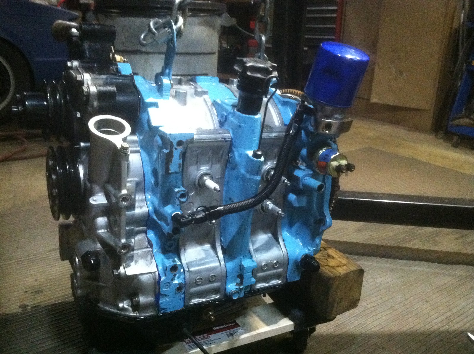 IMG_1561 by thomas telesco, on Flickr