When you click on links to various merchants on this site and make a purchase, this can result in this site earning a commission. Affiliate programs and affiliations include, but are not limited to, the eBay Partner Network.
Hey everyone, I've been hunting around, trying to find the information needed to do the external oil line modification. It's the one where oil is routed in/out the side galleys of the front iron and bypasses the front cover and the dowel pin running between the oil filter pedestal and the front stationary gear. I generally have a good idea of how to accomplish this now, but I haven't found much about sizing of the -AN fittings. A lot of the pictures in threads detailing how it's done are also missing, so it's hard to even ballpark them. I've seen someone mention (probably Banzai Racing) that they put -8AN fittings in the center iron of a 20B, but looking at my S4T2, that looks a bit large for the side oil galleys in the front iron. What size fittings did you all use for this modification?
I would not use pipe fitting bends (tight radius bend) since you are specifically doing this mod to decrease the pressure drop of the oil going to the front bearing.
Straight off the oil filter pedestal adapter, between the oil dipstick tube and the housing and down to the front oil plug galley and then a 90 deg hose end fitting (longer radius mandrel bend).
Tap the side housing with straight threads (instead of tapered pipe threads) and seal with a crush washer so you don't crack the cast iron.
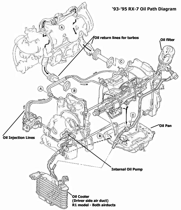
Digging this up again. My question is more on the actual line routing. My plan is to plug the front cover feed and use solid dowels. I've looked at pics of only one line in front cover and also two. I can't find a definite answer on routing tho and all threads the pics are gone. I am planning on front oil pump out iron to cooler, cooler out to remote filter mount, filter mount to rear iron, then a oil filter adapter of some sort feeding front bearing through front iron and also adapter feeding turbo. Does that sound like proper routing? Thanks
-6an oil into the front bearing and -10an oil out to the oil cooler.
If you see one with one line they are using the (convoluted) front cover's oil cooler outlet still.
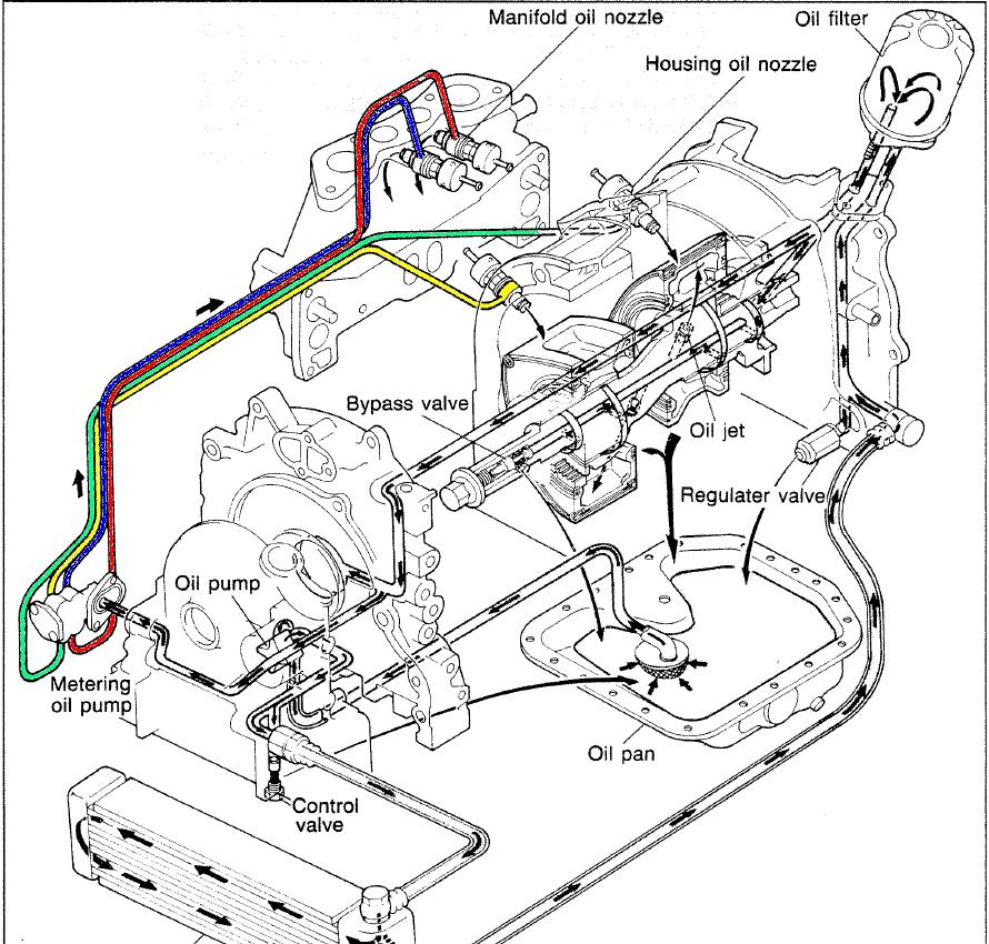
If you block oil flow to the front cover you lose your cold start oil pressure relief valve, oil to the CAS gear and oil to the oil metering pump.
I used a hollow dowel between the front cover and stock oil pump outlet to keep the o-ring in place (it kept popping out) and just blocked front cover oil cooler outlet.
I almost feel like I shouldn't tell anyone how it is done because if one can't reason out the system they probably shouldn't be doing the modifications...
I used a hollow dowel between the front cover and stock oil pump outlet to keep the o-ring in place (it kept popping out) and just blocked front cover oil
Doesn't a metal front cover gasket eliminate the
Téflon o-ring ?
And also,
I'm no expert by if the oil pressure doesn't go to the front cover (if installed) isn't it enough for the teflon o-ring to NOT to fall , since pressure is by-pass.
Last edited by 7krayziboi; Mar 14, 2017 at 11:48 AM.
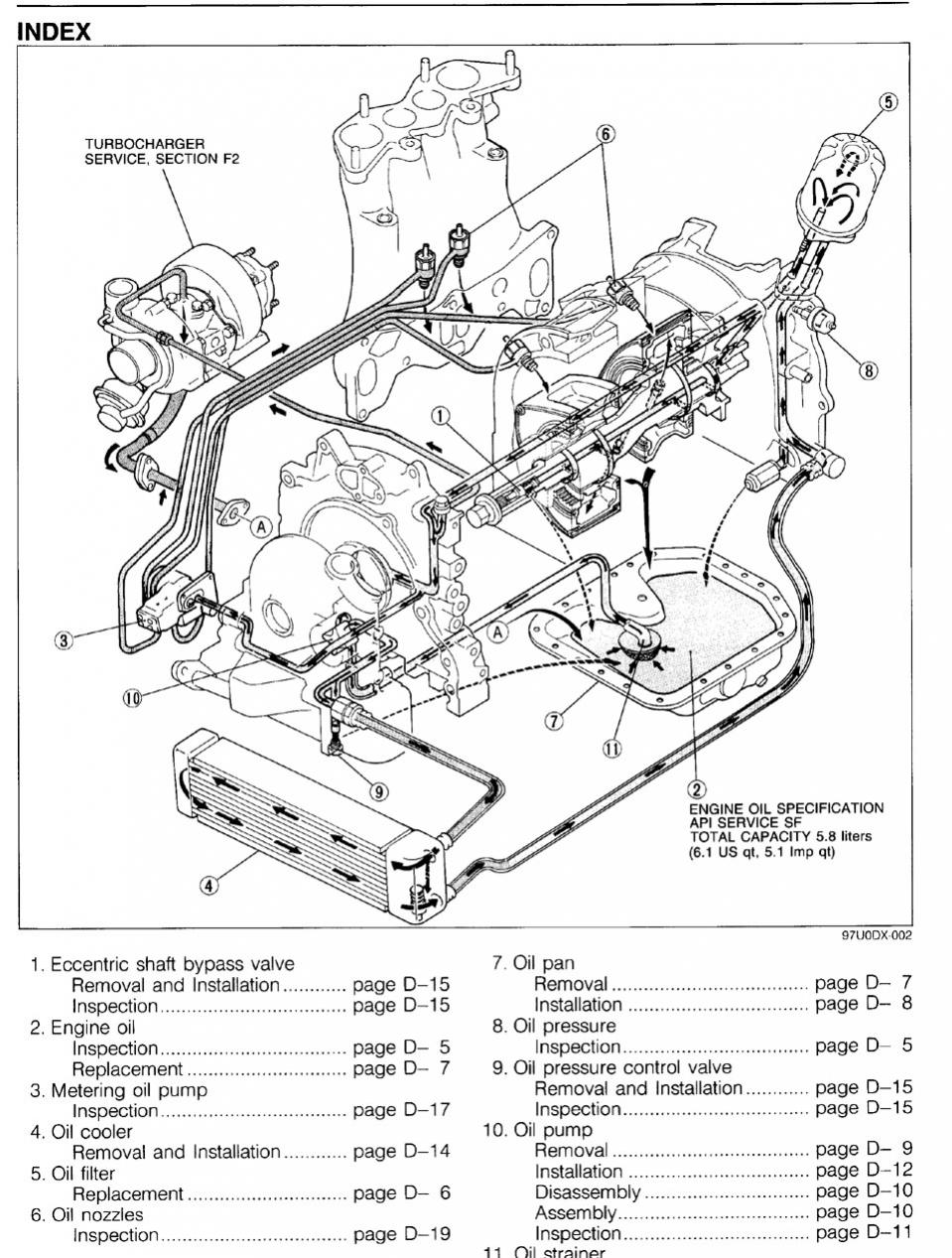
What diagram is that for, BLUE_TII? It looks EFI, but has a distributor. IIRC, FCs have an oil thermostat in the oil cooler and the front pressure regulator bypasses straight into the pan, not through the bottom of the engine to rear pressure regulator. Early euro 13B, or GSL-SE engine?
And to be fair to siguy2k, I had troubles figuring out this modification until I actually cracked open a 13B. It's a bit hard to understand when there's no pictures left anywhere. When I asked this question, I hadn't ever seen the inside of a 13B until now, and didn't really have the means of doing so (I didn't have irons to spare lying around). Now that I have, I could go back into the threads without pictures and actually understand what they're saying.
Also, to 7krayziboi, the metal front cover gasket is all inclusive. If you use it, you won't need to worry about the teflon ring or the o-ring, and since they're built into the gasket, they won't fall out (unless the gasket falls down too, but then you have other problems to worry about as well). I'm not sure what you mean, with the whole pressure bypass preventing the o-ring from falling. The hollow dowel comment was just to keep a means of preventing the o-ring from falling without blocking oil flow.
The hollow dowel comment was just to keep a means of preventing the o-ring from falling without blocking oil flow.
Keeping the o-ring in place and also leaking less than o-ring or metal gasket when the oil pressure does push the front cover away from the front side housing.
Mazda just missed putting a boss and bolt there next to the oil pump outlet when they designed the engine. In the '60s they must not have imagined how high they would jack the pressure up on the 13B-REW.
Here's the 13B-REW iron I got from some big time drag racers in PR. Identical irons from the builder have been low 7s in the 1/4 .
It looks like they slipped a piece of tubing into the galley and ground it flush. This way, if the dowel casting broke, you wouldn't lose oil pressure and could finish the pass.
If anyone's interested, this iron is for sale :?
What size fitting are you running in the front iron?
As for using the compressor, You have to either use a sharp 90 bend fittings straight in the front iron or space out the AC compressor last time I checked.
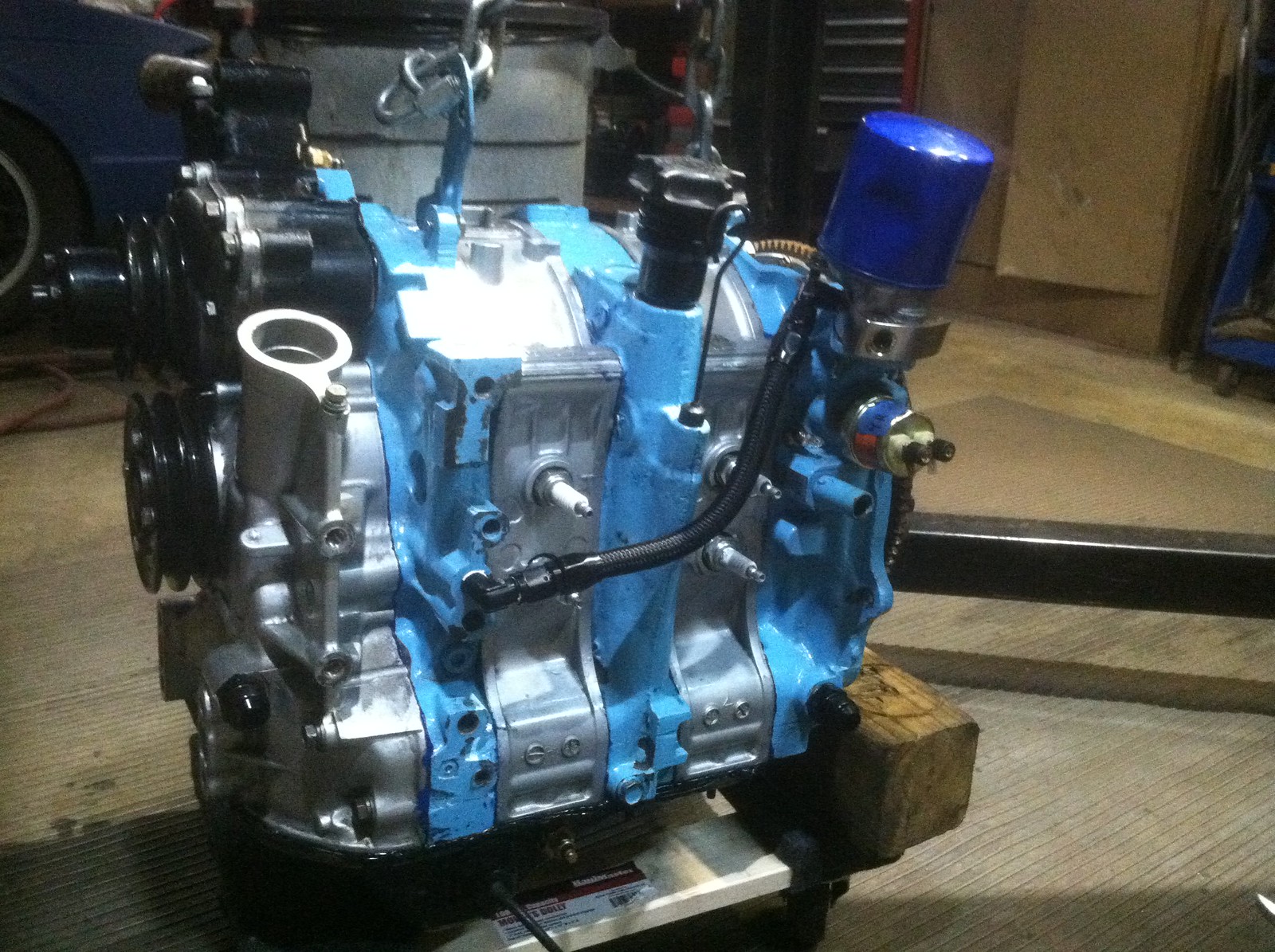
Sorry for the poor quality pics but here is how I did mine. all -6 size and an NPT to AN adapter into the front housing. Also if your going this far, I would suggest port matching the opening in the stationary gear to the opening in the iron. I'm no scientist but during my research for oil modifications I found that walls in the system are bad and most of the ports in the oiling system don't match up very well.
Sorry for the poor quality pics but here is how I did mine. all -6 size and an NPT to AN adapter into the front housing. Also if your going this far, I would suggest port matching the opening in the stationary gear to the opening in the iron. I'm no scientist but during my research for oil modifications I found that walls in the system are bad and most of the ports in the oiling system don't match up very well.
Your engine bay looks sweet. I'll check on the port alignment when I get to that hurdle.
I'm going to try a steel M16x1.5 to -8AN fitting with a crush washer, to see if I can't squeeze a larger fitting in there than the usual -6AN. -8AN ORB looks too scary for the lower front iron passage.
Bringing an old thread back to life. I understand the concept and the idea behind it. I understand reasoning behind it (Due to running a solid one piece dowel in the upper dowel location.) Just have one question for it. You end up using the oil galley passage in the front iron lower section to supply oil from the rear of the engine via a pedestal. On the Turbo, you supply oil to the turbo via the front iron top port, with the solid dowel is this location blocked as well or does it still function? I'm no fluid dynamics person, but even looking at the oem flow path, I don't see how well it would work in the first place as it has to flow backwards and up. Any input from people who have done it?
Correct , the flow change direction from the top of the front iron (blocked by solid dowel) to the center of it where the new oil feed is.
The main direction of the oil coming from the pedestal will be to the front bearing as it's now in a straight path to it , (compare to the 2 extra 90• angle the OEM system use).
On the OEM setup , the oil has to go up the front iron (just a little) to feed the the turbo through the oil galley from the rear iron.
This mods basically eliminates 3 90•angle in the the OEM oil system (or 5 if use straight Feed/Return fitting)
But the loop line mod was not created to make the oiling system work with solid dowels (though it does work for that purpose) it was created to increase and balance oil flow into the front and rear of the eccentric shaft for the rotor bearing and rotor cooling.
The factory eccentric has some efforts to balance the flow by having just one oil entry hole in the rear main bearing journal while providing two oil entries on the front main bearing journal (to make up for all the oil pressure and flow loss from the convoluted oil path to the front main bearing.
The loop line mod is to make a smooth passage for oil directly into the front main bearing area for the highest possible pressure and flow.
Then you can go ahead and add the second oil entry onto the rear main bearing journal.
Balance is important because the oil flow will follow the path of least resistance. Too much flow in the rear and you could starve the front (and vice versa).
Another trick you can do to increase oil flow into and out of the eccentric shaft to feed the rotor bearing and rotor cooling jets is to relive the entry and exit holes.
Another way you can increase oil flow to the rotor bearings is to limit oil cooling flow by putting in the Mazdacomp restricted oil cooling jets or the Webber jet mod to restrict flow.
Stock
Restricted
But the loop line mod was not created to make the oiling system work with solid dowels (though it does work for that purpose) it was created to increase and balance oil flow into the front and rear of the eccentric shaft for the rotor bearing and rotor cooling.
The factory eccentric has some efforts to balance the flow by having just one oil entry hole in the rear main bearing journal while providing two oil entries on the front main bearing journal (to make up for all the oil pressure and flow loss from the convoluted oil path to the front main bearing.
The loop line mod is to make a smooth passage for oil directly into the front main bearing area for the highest possible pressure and flow.
Then you can go ahead and add the second oil entry onto the rear main bearing journal.
Balance is important because the oil flow will follow the path of least resistance. Too much flow in the rear and you could starve the front (and vice versa).
Another trick you can do to increase oil flow into and out of the eccentric shaft to feed the rotor bearing and rotor cooling jets is to relive the entry and exit holes.
Another way you can increase oil flow to the rotor bearings is to limit oil cooling flow by putting in the Mazdacomp restricted oil cooling jets or the Webber jet mod to restrict flow.
Stock
Thank you both for the information. These are both things I haven't been able to find using google searches. I understood the loopline mod being needed for the solid dowel to be able to feed the front rotor as you blocked the path when installing both solid dowels. I did not know that there was added benefits for doing it without the solid dowels, as I am sitting here doing research for the next build and attempting to make a motor that will outlast the turbo for that time when I decide my current setup is not enough.
So, if you where to solid dowel it in both locations with the loopline mod, would it be necessary to add the additional inlet to the rear main bearing as you had mentioned?
So, if you where to solid dowel it in both locations with the loopline mod, would it be necessary to add the additional inlet to the rear main bearing as you had mentioned?
I have no experience with solid dowels. You would have to take the localized oil pressure readings before and after adding the loop line mod to find out. You also have the variable of what size and shape AN fittings/hose you use for the loop line. -8AN is the norm and usually there are two 90 deg mandrel bend AN hose ends used, but it could be done with bigger hose and straight AN fittings with a big loop in the hose.
In my mind dowels with some give would be "stronger" than solid dowels. If the engine is detonating and the rotor housings are deforming and wrenching the side housings through the dowel pin I would rather have a dowel pin with give to dampen the shock loads. I would drill out the side housings and put in a soft metal bushing for the dowel pin to ride in to help prevent cracking of the side housings under detonation hammering before I would make the dowel pins more rigid. Or better, machine the dowels down so a soft metal sleeve fits over the ends that will be in the side housings.
I guess the drag idea is to finish the pass with the cracked side housing and without oiling down your rear tires, so solid dowels is like a couple second bandaid.


 IMG_1561 by thomas telesco, on Flickr