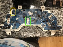
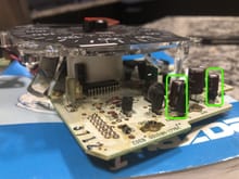
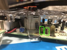
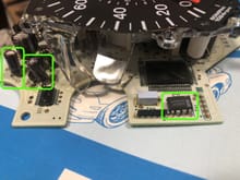
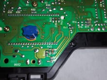
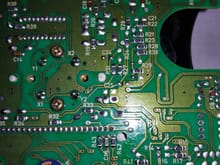
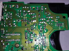
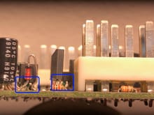
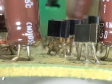
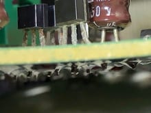
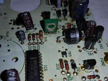
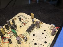
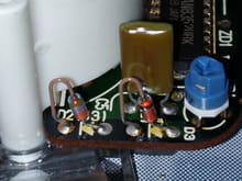
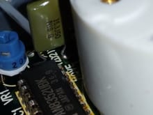
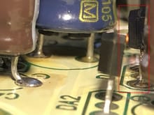
Take a closer look at these 2 capacitors, C4 and C6. Their tops look bulged out, which is a sign of replacement. Take a closer photo then post.
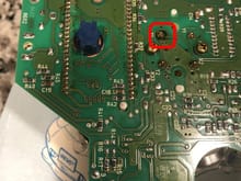
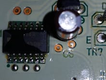
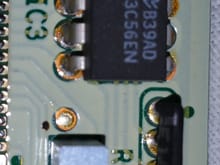
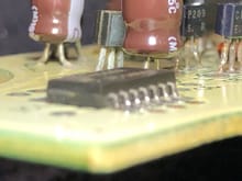
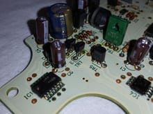
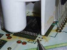
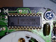
Take another look at IC3. It looks crooked. Make sure that each leg does not touch one another. This chip stores the odometer reading.