
Electromotive **!**The Offical ELECTROMOTIVE TEC Install thread**!**


Eh, turns out my used Tec3r is DOA. Beware the used engine management system.  Guy that sold it to me made it sound like it had a nice harness too. Yeah, that went in the trash. Hopefully Electromotive will treat me nicely and kiss me before they fix this thing.
Guy that sold it to me made it sound like it had a nice harness too. Yeah, that went in the trash. Hopefully Electromotive will treat me nicely and kiss me before they fix this thing.
Thread Starter
Joined: May 2003
Posts: 7,831
Likes: 2
From: Hagersville Ontario
Some small updates.
I'm rolling on it pretty heavy now, have most of the harness figured out. Just taking my time planning all of the circuits for the rest of the car (redoing all wiring to EVERYTHING I've ever installed in the car)
Here's some pics:
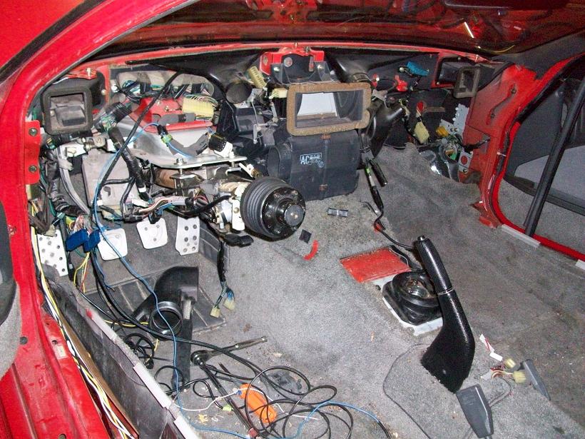
Current state of interior, sans dashboard.

Here's a test crimp I made with a weather pack 150 pin. Let me just say, I will never again in my life attempt to build any type of wiring using anything other then **PROPERLY** crimped pins in new connectors....this thing does such a beautiful job that I get a little weepy when I look at it.

TEC harness connector all bundled and divided up. That expandable sleeving is the ****! Don't get you finger in it though, its a chinese finger trap!
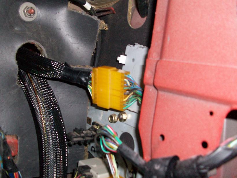
Never took a shot of this before because I couldn't get a good one with the dash in. But the connector pictured here is KEY for any install of a standalone in a 2nd gen. That plug contains the wires for your cruise control (if equipped), stock coolant temp sensor, stock cooling fan sensor, wipers and other "usually kept" feautres. The harness will untangle out ot the factory harness, and unplug there. VOILA - no cutting or rewiring needed.
Just a shot of one of the weatherpack plugs I'm using through out the car. After wiring stuff, and taking thigns back apart, you get extremely frustrated cutting wires and rejoining them. "think ahead" is my motto for '09
Soon to come, engine bay connections, lots of relays and fuses, and much - much more wire!
EDIT: also want to thank Chris Ludwig for the speedy delivery of the connectors for all my engine's sensors. Thanks buddy!
I'm rolling on it pretty heavy now, have most of the harness figured out. Just taking my time planning all of the circuits for the rest of the car (redoing all wiring to EVERYTHING I've ever installed in the car)
Here's some pics:
Current state of interior, sans dashboard.
Here's a test crimp I made with a weather pack 150 pin. Let me just say, I will never again in my life attempt to build any type of wiring using anything other then **PROPERLY** crimped pins in new connectors....this thing does such a beautiful job that I get a little weepy when I look at it.
TEC harness connector all bundled and divided up. That expandable sleeving is the ****! Don't get you finger in it though, its a chinese finger trap!
Never took a shot of this before because I couldn't get a good one with the dash in. But the connector pictured here is KEY for any install of a standalone in a 2nd gen. That plug contains the wires for your cruise control (if equipped), stock coolant temp sensor, stock cooling fan sensor, wipers and other "usually kept" feautres. The harness will untangle out ot the factory harness, and unplug there. VOILA - no cutting or rewiring needed.
Just a shot of one of the weatherpack plugs I'm using through out the car. After wiring stuff, and taking thigns back apart, you get extremely frustrated cutting wires and rejoining them. "think ahead" is my motto for '09
Soon to come, engine bay connections, lots of relays and fuses, and much - much more wire!
EDIT: also want to thank Chris Ludwig for the speedy delivery of the connectors for all my engine's sensors. Thanks buddy!
Thread Starter
Joined: May 2003
Posts: 7,831
Likes: 2
From: Hagersville Ontario
Sailing away on a sea of spahetti
Got some more shots of the progress.
I forgot to take a shot of the whole mess on the bench, but it looked pretty up there!
Here's the business end of the engine harness:
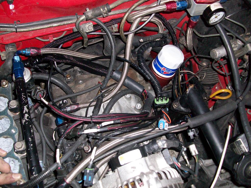
Love using that nylon expandable sleeving. I'm sure there's other better products that exist that I've never seen, but thats a hell of a step up from corrogated loom and electrical tape!!
Here's the coils in their new home. Have to finish the bracket yet, but I needed to rough it in to finish the harness + order custom magnecor wires. Didn't want to be waiting on them
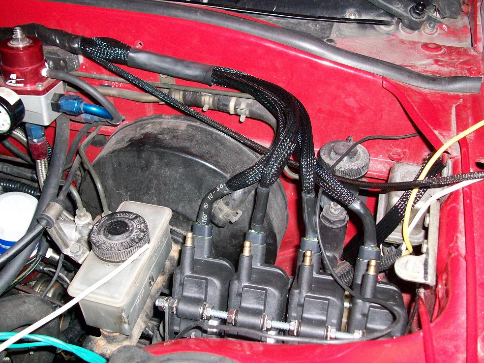
Another shot of the coils:
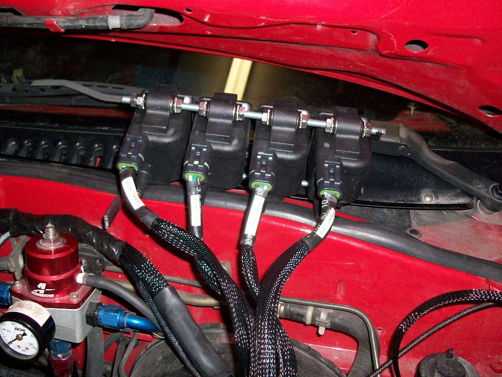
Note the labels. Thanks to the wonderfully brilliant minds around here, I discovered this sweet *** product called clear heat shrink, and I think I'm in love! haha
Firewall grommet. Now - yes, I know I have some fancy schmancy bulkhead connectors to use here, but a few things transpiered:
1) I didn't have enough wires in the bulk heads for everything (gauges, assorted power wires, engine harness, remaining bits of factory harness....)
2) Paranoia surrounding trigger issues, and the two bundles of shielded wires for the coils made it difficult for me to chop that engine harness in half and rejoin it. I'll use them on another car.
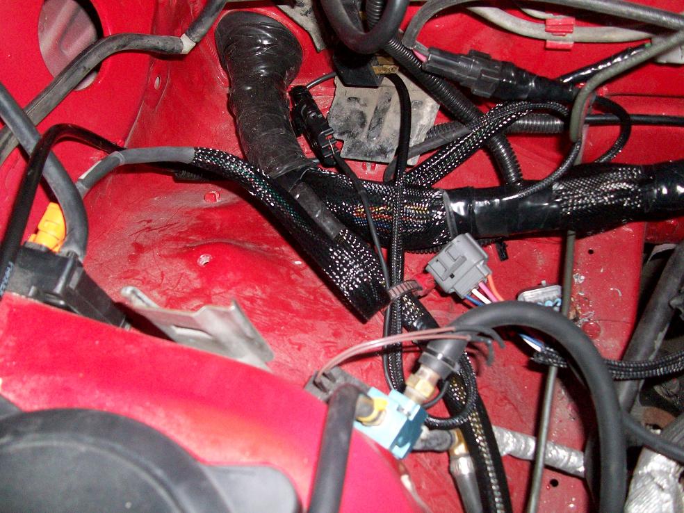
Also, all of the tape used to bind the grommet to the harness (and all other tape on the harness for that matter) is of the silicone, self fusing variety. Myself, I've never used this before now, but would HIGHLY recommend that anyone doing any wiring keep a couple rolls of that stuff around. It seals amazingly well, and *will not* come unravelled.
Lastly, here is what remains to be done on the inside - everything And yeah - they're marked!! haha
 Thats how the inside will stay for a bit. Currently, I've finished the firewall forward portion of the wiring, and have the engine pulled for installation of the (yet to be finished at the machine shop) FD front cover, waterpump etc. When thats all back in, I'll finish the wiring in the cabin and throw some power to that bitch to see what smokes, the wiring or the tailpipe. I've got my fingers crossed for the latter!
Also - sleeper7, in the very near future I'll be looking for an email address I can send you my map on to see if you think it'll work......hopefully you can lend a hand May also get your input on that Chris
I forgot to take a shot of the whole mess on the bench, but it looked pretty up there!
Here's the business end of the engine harness:
Love using that nylon expandable sleeving. I'm sure there's other better products that exist that I've never seen, but thats a hell of a step up from corrogated loom and electrical tape!!
Here's the coils in their new home. Have to finish the bracket yet, but I needed to rough it in to finish the harness + order custom magnecor wires. Didn't want to be waiting on them
Another shot of the coils:
Note the labels. Thanks to the wonderfully brilliant minds around here, I discovered this sweet *** product called clear heat shrink, and I think I'm in love! haha
Firewall grommet. Now - yes, I know I have some fancy schmancy bulkhead connectors to use here, but a few things transpiered:
1) I didn't have enough wires in the bulk heads for everything (gauges, assorted power wires, engine harness, remaining bits of factory harness....)
2) Paranoia surrounding trigger issues, and the two bundles of shielded wires for the coils made it difficult for me to chop that engine harness in half and rejoin it. I'll use them on another car.
Also, all of the tape used to bind the grommet to the harness (and all other tape on the harness for that matter) is of the silicone, self fusing variety. Myself, I've never used this before now, but would HIGHLY recommend that anyone doing any wiring keep a couple rolls of that stuff around. It seals amazingly well, and *will not* come unravelled.
Lastly, here is what remains to be done on the inside - everything
And yeah - they're marked!! haha Thats how the inside will stay for a bit. Currently, I've finished the firewall forward portion of the wiring, and have the engine pulled for installation of the (yet to be finished at the machine shop) FD front cover, waterpump etc. When thats all back in, I'll finish the wiring in the cabin and throw some power to that bitch to see what smokes, the wiring or the tailpipe. I've got my fingers crossed for the latter! Also - sleeper7, in the very near future I'll be looking for an email address I can send you my map on to see if you think it'll work......hopefully you can lend a hand
May also get your input on that Chris
Joe.
What are you using for sheilded wire. I have not purchased any wiring for my autronic install yet. Ideally I want my car running in 4 weeks to make sure everything is good. DGRR2009 will just be around the corner..........
What are you using for sheilded wire. I have not purchased any wiring for my autronic install yet. Ideally I want my car running in 4 weeks to make sure everything is good. DGRR2009 will just be around the corner..........
Thread Starter
Joined: May 2003
Posts: 7,831
Likes: 2
From: Hagersville Ontario
I used what came on the TEC harness. Haven't had to add any (shielded) wiring anywhere.
PM dj55b (sam) he was telling me about some wire he had that he used on his megasquirt install.....might be what you're after.
PM dj55b (sam) he was telling me about some wire he had that he used on his megasquirt install.....might be what you're after.

Banned. I got OWNED!!!
Joined: Jun 2008
Posts: 329
Likes: 0
From: usa
Also, to be honest, I've got a couple other reasons for wanting to use it. The major one being that I'm becoming incresingly disappointed with the dual belt system. Even match pairs I'm finding one will be sloppy after ~5,000kms. I'm not having any slippage trouble, but nonetheless the routing on the FD waterpump is much more ideal in my mind. Some fancy rad piping will need to be made to make up for the different outlet orientaion, but thats simple stuff thats more up my alley fabrication wise.
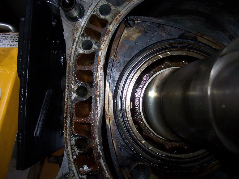
Joe, if you're not going to be running an air pump, can't see why you would, you should look into Chadwicks idler kit over in the GB section if you plan on using the FD wp housing. In the first page he goes into alot of detail about the wear on the main bearings from over tensioning the belts. I can assure you, he isn't lying. My main bearing was pretty trashed after only a few hours with a belt that was way too tight trying to make up for little belt contact.
Also, the only other sna-foo switching to the FD stuff makes, is that there's a *minor* difference in the location of the keyways on the front hub vs an S5. So some marking will need to be made with the engine apart, and the indexing tab on the FD pulley will need to be gorund off so I can rotate the wheel a few degrees to properly align the trailing edge of the 11th tooth with the mag sensor.
Here's some more shots of the "progress" I've made lately.
These are on a J-spec I've torn down for a rebuild and I started mocking up thee trigger stuff.
Here the trigger wheel has been mounted on the original S5 hub. Now, the pic here the engine was rotated slightly advanced, but the second photo shows the engine position when the trailing edge of the 11th tooth is lined up with the mag sensor.

This illustrates the **minor** difference in the S5 and S6 front hubs. This little bit of advance could probably simply be taken into account when laying out the ignition table and be fine........but I'm going to explore a couple options of rotating the wheel, or rotating the hub, or repositioning the sensor slightly to make up for this extremely minor variance.
These are on a J-spec I've torn down for a rebuild and I started mocking up thee trigger stuff.
Here the trigger wheel has been mounted on the original S5 hub. Now, the pic here the engine was rotated slightly advanced, but the second photo shows the engine position when the trailing edge of the 11th tooth is lined up with the mag sensor.
This illustrates the **minor** difference in the S5 and S6 front hubs. This little bit of advance could probably simply be taken into account when laying out the ignition table and be fine........but I'm going to explore a couple options of rotating the wheel, or rotating the hub, or repositioning the sensor slightly to make up for this extremely minor variance.
Well last night I prepared the FD trigger pulley to allow the TEC trigger wheel to be rotated on it (ie. ground off that tab)
But it should be noted that the actual difference in pulley's between S5 and S6 is notable. Looking at the pulleys the difference seems extremely minimal, but when you mount it all up....its pretty big.
I could line the rotor up at a visual TDC, and find my trigger wheel lined up on the trailing edge of the 10th tooth. One tooth, no biggie yes? Well if my math is correct, one tooth on a 60 tooth setup = 6 degrees. So if you left it this way and ran true timing numbers - you'd be 6 degrees advanced across the board.
Wiring coming soon....
 That minor difference of 6* can easily be the difference from a great running engine and a bunch of new parts for powdercoating as show pieces. Nice find on the pulley differences though Joe, very note worth stuff. Personally I went the simpler route - Motec with the CAS. I completely understand and agree with your reasons for going this route though. Kudos for picking up on the *minor* differences.
I've been taking pictures this year of the harnesses I've built and plan to put together a blog about constructing quality harnesses. It's sad to me that so many people a) are scared of wiring a standalone, and b) when they do it 90% of the people do it poorly and that poor install leads to problems and unjust frustration with the system. Not sure when the blog will happen but I'd like to have it up by the end of the year.
Your harness looks great though Ludwig.
Here's a test crimp I made with a weather pack 150 pin. Let me just say, I will never again in my life attempt to build any type of wiring using anything other then **PROPERLY** crimped pins in new connectors....this thing does such a beautiful job that I get a little weepy when I look at it.
 Yeah it is! Where'd you get yours from, Joe? McMaster? I think I need to pick a bunch up for when I put my front chassis harness back together. Screw the split-loom and 3 rolls of Super 33+
Never took a shot of this before because I couldn't get a good one with the dash in. But the connector pictured here is KEY for any install of a standalone in a 2nd gen. That plug contains the wires for your cruise control (if equipped), stock coolant temp sensor, stock cooling fan sensor, wipers and other "usually kept" feautres. The harness will untangle out ot the factory harness, and unplug there. VOILA - no cutting or rewiring needed.
Got some more shots of the progress.
I forgot to take a shot of the whole mess on the bench, but it looked pretty up there!
Here's the business end of the engine harness:
Love using that nylon expandable sleeving. I'm sure there's other better products that exist that I've never seen, but thats a hell of a step up from corrogated loom and electrical tape!!
The ont advantage the expandable sleeve stuff has over the raychem though is the re-using of it. If you wanted to add a wire, you could potentially score the heatshrink and they reheat it, effectively letting it cut itself. Open the expandable stuff up, run your extra wire, and apply some more heat shrink. With a completed Raychem harness..... you almost eff'ed. I got lucky when I had to add a few extra wires to my aux harness as the main joint was pretty close to the bulkhead. If I needed to add something to my engine harness, I'd be screwed... completely.
So how's it looking Joe? Be ready for DGRR? Everything looks great so far.
Thread Starter
Joined: May 2003
Posts: 7,831
Likes: 2
From: Hagersville Ontario
Yep it'll be at DGRR
Got the car running last week and have been putting a few miles on it.
Overall impressions of the system:
Pretty idiot proof if there is such a thing. I had alot of help from some great members (sleeper7, chuck and GTOrx7, logan from Defined Autoworks) to get a base map gathered up, but after a while of tinkering with the car I've found that the software will set you on a pretty good path, save for a pretty bare ignition map. The wizard will generate a map good enough to fire it up, and get you on your way.
As I said though, its pretty idiot proof. Wire up your sensors correctly, and mount you trigger correctly and it WILL work rest assured. I do like the fact that coming from something with trigger issues, this ECU is either going to get PROPER timing and run, or not run at all. The only thing you can screw up is mounting the trigger wheel at anywhere other then TDC - if you DO screw that up, by a tooth or two, you can alter the edge setting in the software and make up for it - but you have to know which tooth it went to thats all.
The biggest thing in setting it up I've found so far, is the HUGE importance of TOG and IOT. You'll beat your head against the wall until those values are set properly, the wizard should get you close.
Also, when you're first starting out then tune, and you're fooling with IOT/TOG, zero out the VE map - but don't load the car up at all. Just do various steady state checks to see where the AFR's are. When I found my current TOG IOT settings (7.9ms and 1ms) with the VE table 0'd out the car would go very lean tipping in the throttle, but that can be taken out with VE adjustments.
I've encountered a couple odd little setting things, but nothing earth shattering - seems like every piece of EMS software has its little "moods". But this one is actually very well behaved. So far, and knock on wood, everything I've setup in the ECU works as far as auxilary stuff. The wideband works and is calibrated, the internal dataloggin works great, the tach (FC) is driven well (and truth be told its slightly more accurate then it was when it was factory!!) the only thing I'm having trouble dialing in is the speed input, but I beleive its related to the rough signal Im tapping into (output from the speedometer).
OH, and so far although I haven't wound out a full boost pass with lots of water AI I believe this iginition system is pretty powerful. Compared to my old setup (stock coils with a haltech) this system has no trouble lighting 9.5 ratios. Sure, its sluggish at those ratios, but with the old system the car would've completely hit a wall. I was able to notice them and correct them without a massive smack in the face when it got drown with gas.
So far, so good - very pleased!
Some setup details for those interested:
Hardware
S5 engine - very very mild intake/exhaust porting (stock overlap)
T04-R
750pri 1600sec (low imp)
Nippondenso pump (38psi base)
stock 9 plugs
Settings
TOG - 7.9
IOT - 1
Minimum turn on time - 0.9
4amp peak
If anyone running this system needs a base map, I'd be more then happy to return the favour that my friends extended me.
I'll link the dyno thread to this one when I get back from the road trip and wring this bitch out!
Got the car running last week and have been putting a few miles on it.
Overall impressions of the system:
Pretty idiot proof if there is such a thing. I had alot of help from some great members (sleeper7, chuck and GTOrx7, logan from Defined Autoworks) to get a base map gathered up, but after a while of tinkering with the car I've found that the software will set you on a pretty good path, save for a pretty bare ignition map. The wizard will generate a map good enough to fire it up, and get you on your way.
As I said though, its pretty idiot proof. Wire up your sensors correctly, and mount you trigger correctly and it WILL work rest assured. I do like the fact that coming from something with trigger issues, this ECU is either going to get PROPER timing and run, or not run at all. The only thing you can screw up is mounting the trigger wheel at anywhere other then TDC - if you DO screw that up, by a tooth or two, you can alter the edge setting in the software and make up for it - but you have to know which tooth it went to thats all.
The biggest thing in setting it up I've found so far, is the HUGE importance of TOG and IOT. You'll beat your head against the wall until those values are set properly, the wizard should get you close.
Also, when you're first starting out then tune, and you're fooling with IOT/TOG, zero out the VE map - but don't load the car up at all. Just do various steady state checks to see where the AFR's are. When I found my current TOG IOT settings (7.9ms and 1ms) with the VE table 0'd out the car would go very lean tipping in the throttle, but that can be taken out with VE adjustments.
I've encountered a couple odd little setting things, but nothing earth shattering - seems like every piece of EMS software has its little "moods". But this one is actually very well behaved. So far, and knock on wood, everything I've setup in the ECU works as far as auxilary stuff. The wideband works and is calibrated, the internal dataloggin works great, the tach (FC) is driven well (and truth be told its slightly more accurate then it was when it was factory!!) the only thing I'm having trouble dialing in is the speed input, but I beleive its related to the rough signal Im tapping into (output from the speedometer).
OH, and so far although I haven't wound out a full boost pass with lots of water AI
I believe this iginition system is pretty powerful. Compared to my old setup (stock coils with a haltech) this system has no trouble lighting 9.5 ratios. Sure, its sluggish at those ratios, but with the old system the car would've completely hit a wall. I was able to notice them and correct them without a massive smack in the face when it got drown with gas.So far, so good - very pleased!
Some setup details for those interested:
Hardware
S5 engine - very very mild intake/exhaust porting (stock overlap)
T04-R
750pri 1600sec (low imp)
Nippondenso pump (38psi base)
stock 9 plugs
Settings
TOG - 7.9
IOT - 1
Minimum turn on time - 0.9
4amp peak
If anyone running this system needs a base map, I'd be more then happy to return the favour that my friends extended me.
I'll link the dyno thread to this one when I get back from the road trip and wring this bitch out!

this has been quite the thread so far. great consumer-oriented info and examples of outstanding work. until earlier tonight, i had my heart set on Autronic for my future REW-build, but i'm really liking the TEC-gt.
thanks.
thanks.
Thread Starter
Joined: May 2003
Posts: 7,831
Likes: 2
From: Hagersville Ontario
****WARNING TO ALL TECgt USERS GPI ISSUE******
Logan @ Defined autoworks has discovered an issue that cropped up on a previous customers car - and showed its face on mine as well.
When wiring the TEC, with the intention of using it on a rotary, DO NOT attempt to use GPI/O 5-7 as if you have GPI/O 5, 6 or 7 enabled at all IT WILL CANCEL OUT THE OPERATION OF YOUR REAR ROTOR'S SECONDARY INJECTOR
As long as you have those GPI's diabled, it will work fine. But do not attempt to wire any of those up for use unless you like popping rear rotors.
Reason behind this is that GPO channel 6 is tied into injector channel 6 - the one running your rear secondary. And although you would think setting it to rotary mode would make any GPO settings you make be cancelled out on that channel, its a small oversight on their part that could cost some engines.
As long as those channels are set to "disabled" the injectors will work fine. Just run your fans, and whatever other thigns you choose on different channels.
Odd software issue, we'll be bringing it to Electromotive's attention and it can hopefully be addressed in a later firmware update.
Thanks
Thread Starter
Joined: May 2003
Posts: 7,831
Likes: 2
From: Hagersville Ontario
Not much to update. Car is running very well.
Only thing thats gone a little south is the operation of my check engine light.
I wired it into the FC idiot light panel along with a shift light and datalog status light. I'm not sure though if the actual input for the CEL is dinked, or if the wiring inside the panel is getting ground from somewhere, but the light just stays on (doesn't blink like it should if theres an error) but I haven't torn it apart to look because Ive been too busy using the car The shift light and datalog status lights work fine. I'm sure the CEL is just getting ground from somewhere inside the panel.......its was a very odd wiring job I did because different lights in the idiot panel get ground from different places............long story.
Solid ECU, very solid ignition and pretty easy to setup.
Only thing thats gone a little south is the operation of my check engine light.
I wired it into the FC idiot light panel along with a shift light and datalog status light. I'm not sure though if the actual input for the CEL is dinked, or if the wiring inside the panel is getting ground from somewhere, but the light just stays on (doesn't blink like it should if theres an error) but I haven't torn it apart to look because Ive been too busy using the car
The shift light and datalog status lights work fine. I'm sure the CEL is just getting ground from somewhere inside the panel.......its was a very odd wiring job I did because different lights in the idiot panel get ground from different places............long story.Solid ECU, very solid ignition and pretty easy to setup.
Water Injection Specialist
Joined: Apr 2003
Posts: 479
Likes: 0
From: UK
Not much to update. Car is running very well.
Only thing thats gone a little south is the operation of my check engine light.
I wired it into the FC idiot light panel along with a shift light and datalog status light. I'm not sure though if the actual input for the CEL is dinked, or if the wiring inside the panel is getting ground from somewhere, but the light just stays on (doesn't blink like it should if theres an error) but I haven't torn it apart to look because Ive been too busy using the car The shift light and datalog status lights work fine. I'm sure the CEL is just getting ground from somewhere inside the panel.......its was a very odd wiring job I did because different lights in the idiot panel get ground from different places............long story.
Solid ECU, very solid ignition and pretty easy to setup.
Only thing thats gone a little south is the operation of my check engine light.
I wired it into the FC idiot light panel along with a shift light and datalog status light. I'm not sure though if the actual input for the CEL is dinked, or if the wiring inside the panel is getting ground from somewhere, but the light just stays on (doesn't blink like it should if theres an error) but I haven't torn it apart to look because Ive been too busy using the car
The shift light and datalog status lights work fine. I'm sure the CEL is just getting ground from somewhere inside the panel.......its was a very odd wiring job I did because different lights in the idiot panel get ground from different places............long story.Solid ECU, very solid ignition and pretty easy to setup.
****WARNING TO ALL TECgt USERS GPI ISSUE******
Logan @ Defined autoworks has discovered an issue that cropped up on a previous customers car - and showed its face on mine as well.
When wiring the TEC, with the intention of using it on a rotary, DO NOT attempt to use GPI/O 5-7 as if you have GPI/O 5, 6 or 7 enabled at all IT WILL CANCEL OUT THE OPERATION OF YOUR REAR ROTOR'S SECONDARY INJECTOR
As long as you have those GPI's diabled, it will work fine. But do not attempt to wire any of those up for use unless you like popping rear rotors.
Reason behind this is that GPO channel 6 is tied into injector channel 6 - the one running your rear secondary. And although you would think setting it to rotary mode would make any GPO settings you make be cancelled out on that channel, its a small oversight on their part that could cost some engines.
As long as those channels are set to "disabled" the injectors will work fine. Just run your fans, and whatever other thigns you choose on different channels.
Odd software issue, we'll be bringing it to Electromotive's attention and it can hopefully be addressed in a later firmware update.
Thanks
Logan @ Defined autoworks has discovered an issue that cropped up on a previous customers car - and showed its face on mine as well.
When wiring the TEC, with the intention of using it on a rotary, DO NOT attempt to use GPI/O 5-7 as if you have GPI/O 5, 6 or 7 enabled at all IT WILL CANCEL OUT THE OPERATION OF YOUR REAR ROTOR'S SECONDARY INJECTOR
As long as you have those GPI's diabled, it will work fine. But do not attempt to wire any of those up for use unless you like popping rear rotors.
Reason behind this is that GPO channel 6 is tied into injector channel 6 - the one running your rear secondary. And although you would think setting it to rotary mode would make any GPO settings you make be cancelled out on that channel, its a small oversight on their part that could cost some engines.
As long as those channels are set to "disabled" the injectors will work fine. Just run your fans, and whatever other thigns you choose on different channels.
Odd software issue, we'll be bringing it to Electromotive's attention and it can hopefully be addressed in a later firmware update.
Thanks
electromotive
Installed this system into a 1993 fd and cannot get veh to idle under 1400 rpms starts to run on one rotor then shuts off , any one have any ideas before we rip it out. also cranks long on first start up backfires and then has a tip in problem goes lean for a second

Thread
Thread Starter
Forum
Replies
Last Post
Jeff20B
1st Generation Specific (1979-1985)
73
Sep 16, 2018 07:16 PM
[For Sale] Scratch & Dent, Used, and Open-Box Sale!
SakeBomb Garage
Vendor Classifieds
5
Aug 9, 2018 05:54 PM
t-von
3rd Generation Specific (1993-2002)
9
Sep 10, 2015 01:56 PM

