
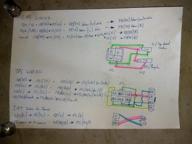
Jap Spec Series 5 FC3S - Twin turbo rew conversion!


Joined: Mar 2001
Posts: 31,851
Likes: 3,239
From: https://www2.mazda.com/en/100th/

Thread Starter
Full Member
Joined: Feb 2011
Posts: 186
Likes: 5
From: Australia
Thread Starter
Full Member
Joined: Feb 2011
Posts: 186
Likes: 5
From: Australia
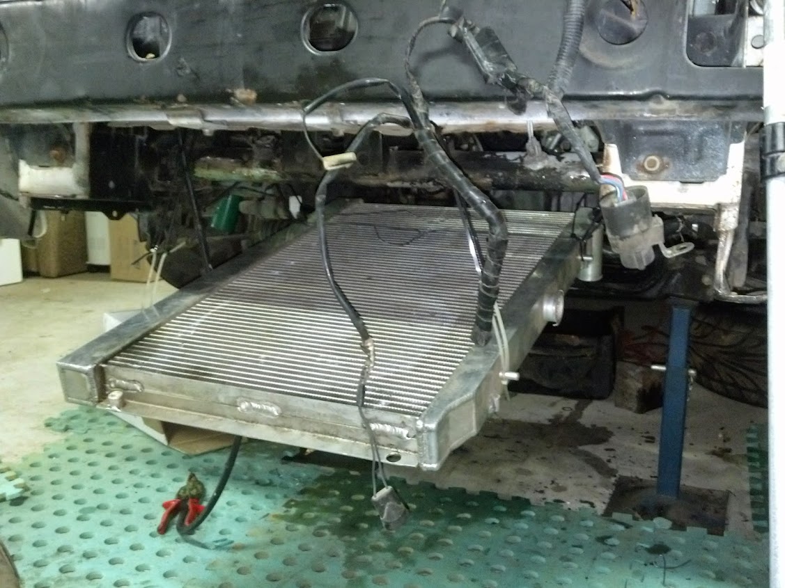
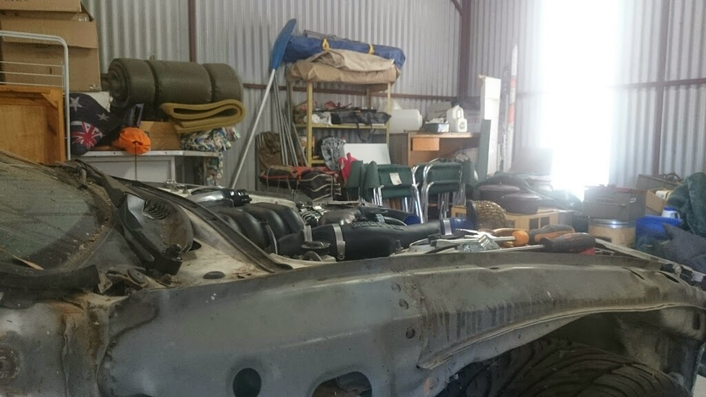
Have started to fab the vmount now,
I'm not really happy with the intercooler i got but it will do in terms of fabbing the mounts, i want the intercooler to sit at a 45 or 30 degree angle this should make the piping really easy and efficient.
I also acquired a cheap alloy rad which i believe to be a nissan r32 or s14 item. This shows the first attempt to mount the radiator length ways unfortunately it then stuck out way too far.


Waiting to be pulled up into place i was using cable ties as it makes it nice and easy to adjust slowly where things will sit

[img]https://lh6.googleusercontent.com/-Pho8E4I4fpU/U4M9bOxZIqI/AAAAAAAACmY/w4iMBlyCA5c/w1127-h845-no/IMG_20140521_173516_613.jpg[img]
[/img]https://lh4.googleusercontent.com/-M6vOIxXY2Rg/U4M9btaRAnI/AAAAAAAACmU/2bJgRQN61B8/w634-h845-no/IMG_20140521_173526_229.jpg[/img]
I had already removed the oil cooling mounts

Round 2
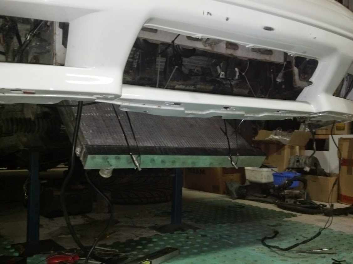
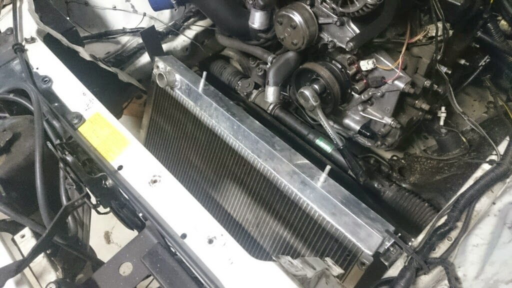
Mounting the radiator the other way, fortunately the rad does fit within the chassis rails unfortunately just!


I'm not really happy with the intercooler i got but it will do in terms of fabbing the mounts, i want the intercooler to sit at a 45 or 30 degree angle this should make the piping really easy and efficient.
I also acquired a cheap alloy rad which i believe to be a nissan r32 or s14 item. This shows the first attempt to mount the radiator length ways unfortunately it then stuck out way too far.
Waiting to be pulled up into place i was using cable ties as it makes it nice and easy to adjust slowly where things will sit
[img]https://lh6.googleusercontent.com/-Pho8E4I4fpU/U4M9bOxZIqI/AAAAAAAACmY/w4iMBlyCA5c/w1127-h845-no/IMG_20140521_173516_613.jpg[img]
[/img]https://lh4.googleusercontent.com/-M6vOIxXY2Rg/U4M9btaRAnI/AAAAAAAACmU/2bJgRQN61B8/w634-h845-no/IMG_20140521_173526_229.jpg[/img]
I had already removed the oil cooling mounts
Round 2
Mounting the radiator the other way, fortunately the rad does fit within the chassis rails unfortunately just!
Thread Starter
Full Member
Joined: Feb 2011
Posts: 186
Likes: 5
From: Australia
The battery was never going to fit in the standard spot with a vmount and always wanted to move it to the boot and now seemed like a good time.
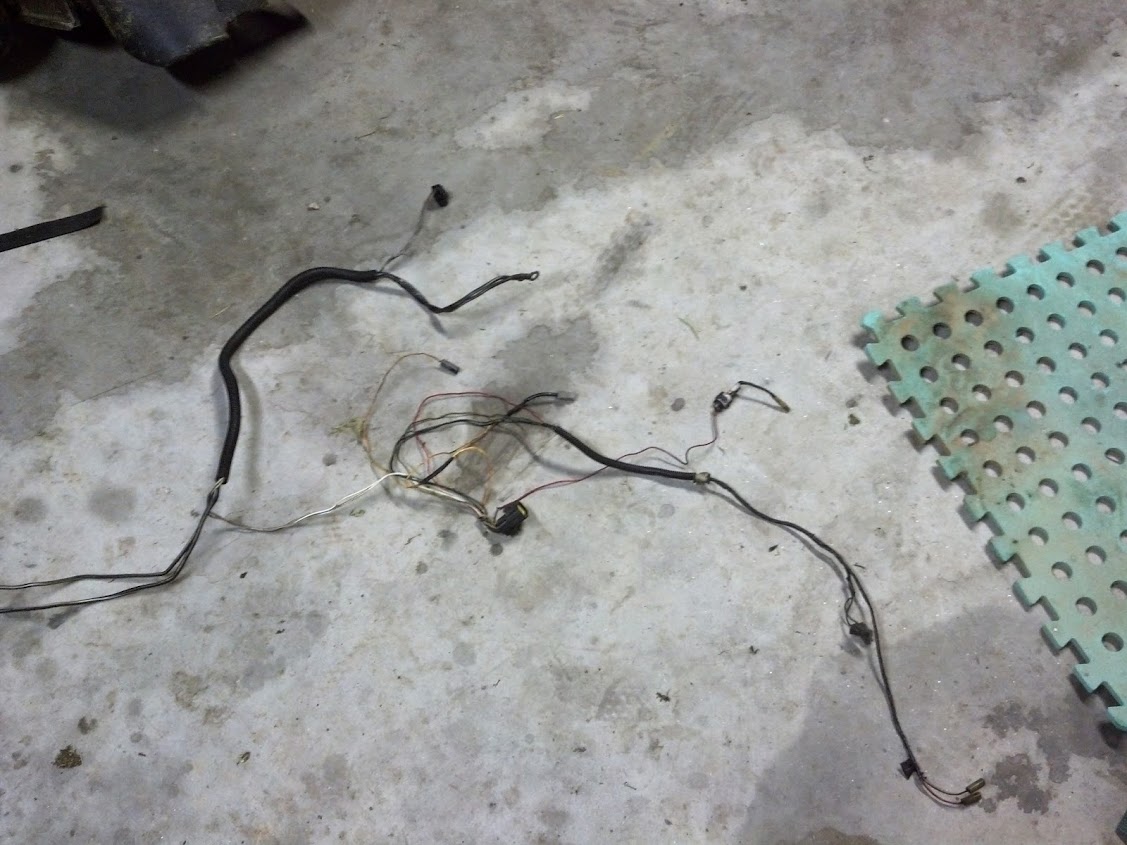
Loom pulled out

Charging loom out
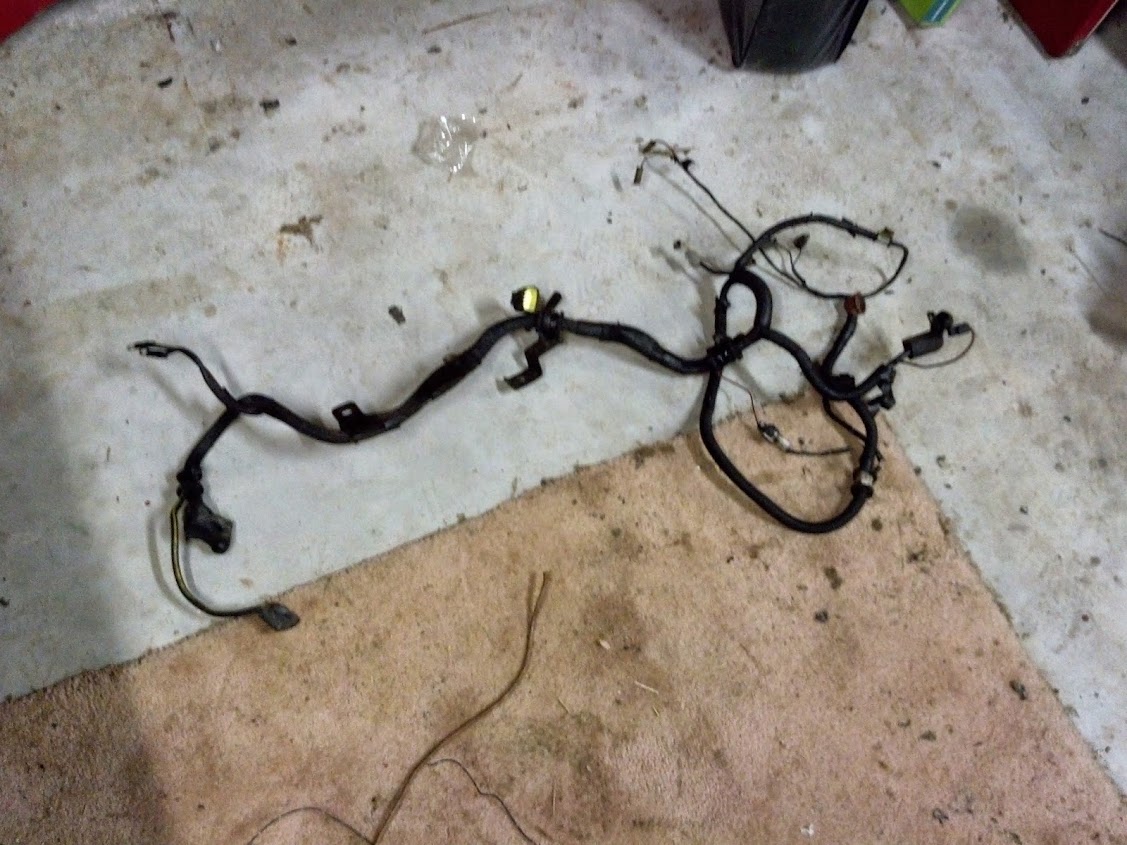
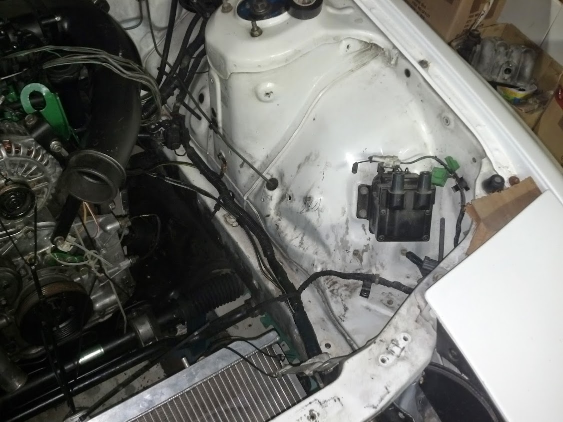
Brown wire is the radiator level,
it was in a terrible spot and needed to be re-located, soo i pulled it further in where the o2 sensor wire is, then conduited them up together and ran them up on top of the motor


Moving back to the charging loom now seperated,

Earth Cable - Black, Yellow line - battery(-) -> chassis -> engine/box
Starter Power - Black - Battery(+) -> Starter
Starter Signal - Black, Red line - Body loom(near other connector) -> starter

Body loom connector middle of picture
Left is the alternator outputs thicker cables
and controller connector
Rest of the connectors are for oil and gearbox sensors
Firstly chopped the earth cable at the chassis terminal as i will reuse both

Then dropped the sensor loom back into the car and tapped the junction points, i also added the starter signal to this section and later removed the output wires of the alternator to clean things up more.

New seperat loom for earth and what will become a jumping point and main fuse power supply using the old power supply cable

Loom pulled out
Charging loom out
Brown wire is the radiator level,
it was in a terrible spot and needed to be re-located, soo i pulled it further in where the o2 sensor wire is, then conduited them up together and ran them up on top of the motor
Moving back to the charging loom now seperated,
Earth Cable - Black, Yellow line - battery(-) -> chassis -> engine/box
Starter Power - Black - Battery(+) -> Starter
Starter Signal - Black, Red line - Body loom(near other connector) -> starter
Body loom connector middle of picture
Left is the alternator outputs thicker cables
and controller connector
Rest of the connectors are for oil and gearbox sensors
Firstly chopped the earth cable at the chassis terminal as i will reuse both
Then dropped the sensor loom back into the car and tapped the junction points, i also added the starter signal to this section and later removed the output wires of the alternator to clean things up more.
New seperat loom for earth and what will become a jumping point and main fuse power supply using the old power supply cable
Thread Starter
Full Member
Joined: Feb 2011
Posts: 186
Likes: 5
From: Australia
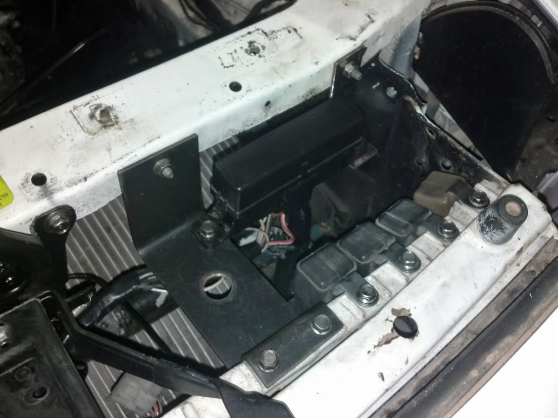
Next went about moving the fuse box to the location of the relays,
fuse wiring exposed at the loom, on the right these 3 wires got extended


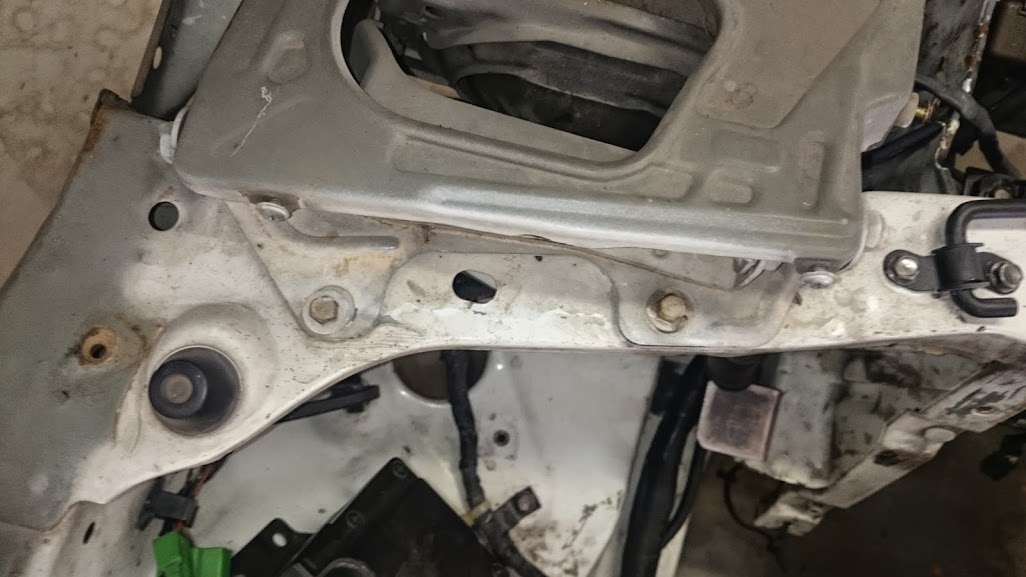
Mounts that i made to relocate the fuse box,
you may also notice the jumping point i was talking about which is original battery power terminal cut and rounded it is insulated from the chassis and should get me out of trouble if ever i needed.


Im really happy with the end result of those brackets i ran out of paint to fix the last one but it is easy enough to remove
fuse wiring exposed at the loom, on the right these 3 wires got extended
Mounts that i made to relocate the fuse box,
you may also notice the jumping point i was talking about which is original battery power terminal cut and rounded it is insulated from the chassis and should get me out of trouble if ever i needed.
Im really happy with the end result of those brackets i ran out of paint to fix the last one but it is easy enough to remove
Thread Starter
Full Member
Joined: Feb 2011
Posts: 186
Likes: 5
From: Australia
After many hour sitting infront and laying under the car i've found where the location for the radiator,
This is it again pulled up into place with cable ties.
The intercooler will sit where the radiator used to, this will also mean it will clear my intake.


I will most likely flip the radiator too, there is a nice cutout for where the oil lines used to run where the pipe could then come out, but not entirely sure as it really doesnt hang very low at all.

And a few more shots of the fuse box relocation, im also really wishing i had of painted the bay now...
This is it again pulled up into place with cable ties.
The intercooler will sit where the radiator used to, this will also mean it will clear my intake.
I will most likely flip the radiator too, there is a nice cutout for where the oil lines used to run where the pipe could then come out, but not entirely sure as it really doesnt hang very low at all.
And a few more shots of the fuse box relocation, im also really wishing i had of painted the bay now...
Thread Starter
Full Member
Joined: Feb 2011
Posts: 186
Likes: 5
From: Australia
Wiring is now hopefully finished,
I cut some holes above that support beam and ran through loom through that.

Definately wouldnt suggest holes any smaller then what i did.

And passenger side
I cut some holes above that support beam and ran through loom through that.
Definately wouldnt suggest holes any smaller then what i did.
And passenger side
Thread Starter
Full Member
Joined: Feb 2011
Posts: 186
Likes: 5
From: Australia
I know i said i'd completed the wiring but i decided to buy a whole bunch of waterproof quick release connectors these are super neat and pretty easy to use.
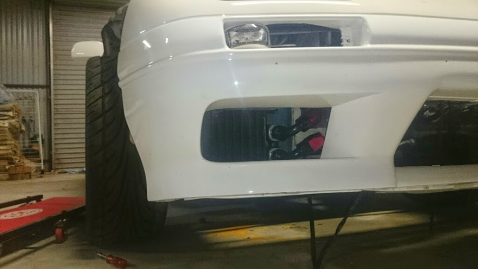
Also added the resistors for the led indicators and the connectors to the front bar

And connectors installed on the fans

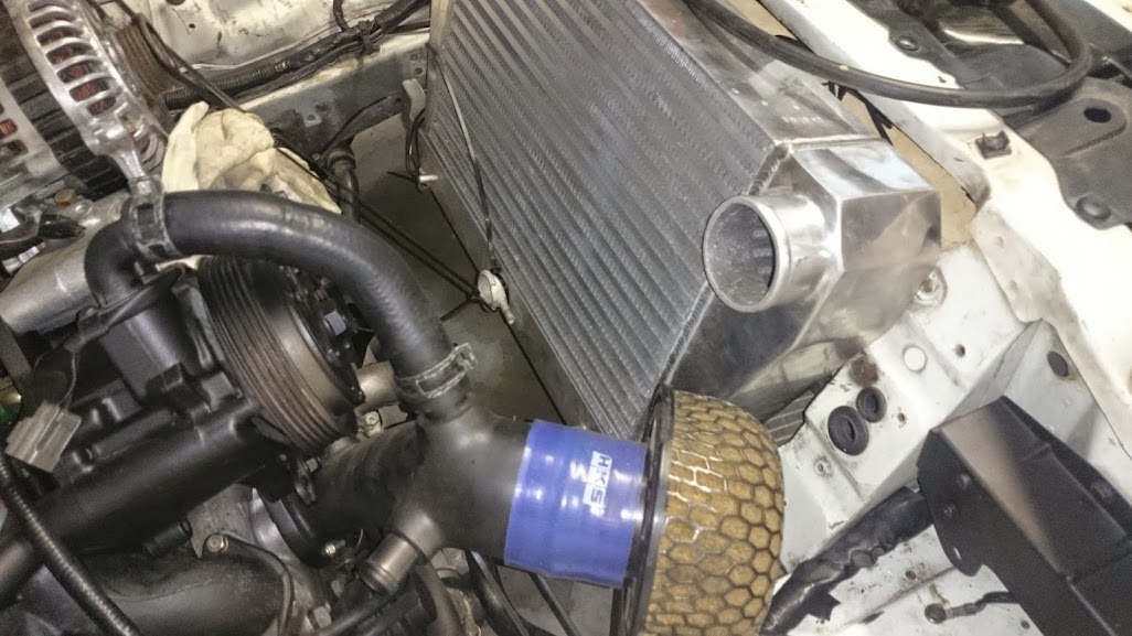
Sold the old intercooler and now have a much better fitting unit, starting to really take shape now


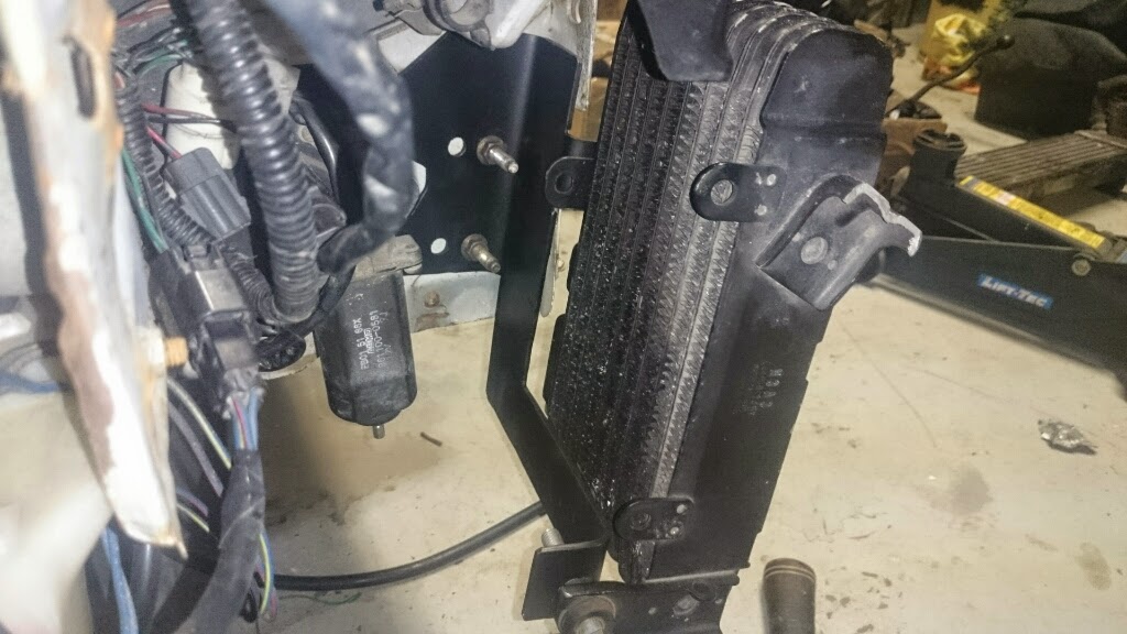
And have worked out oil cooler placement,
It requires one mounting point to be removed but will have nice neat plumbing, clears everything and lines up well with standard vents on the front bar


Also added the resistors for the led indicators and the connectors to the front bar
And connectors installed on the fans
Sold the old intercooler and now have a much better fitting unit, starting to really take shape now
And have worked out oil cooler placement,
It requires one mounting point to be removed but will have nice neat plumbing, clears everything and lines up well with standard vents on the front bar
Thread Starter
Full Member
Joined: Feb 2011
Posts: 186
Likes: 5
From: Australia
My water gaskets were all cracked and and broken, so i've got an order from mazdatrix on the way.
in the mean time decided the water pump housing should get a clean and paint also.


and got my Fc-Hako tuning cable, laptop can now sit in the passenger seat and tell me when theres "danger to manifold"

in the mean time decided the water pump housing should get a clean and paint also.
and got my Fc-Hako tuning cable, laptop can now sit in the passenger seat and tell me when theres "danger to manifold"
Thread Starter
Full Member
Joined: Feb 2011
Posts: 186
Likes: 5
From: Australia
I think the radiator belongs to an r32,
I was actually playing with having the radiator flipped today,
I'll have the whole radiator sitting upside down and back the front, the cap will be cut off and welded.
The IC wont be able to sit in the centre but should hopefully line up better with the turbo outlet and manifold inlet.
Ill attach a bit of right angle aluminium pipe near the top radiator outlet that will then link the bottom outlet to the engine.
This will leave the other side free for the oil hoses and will hopefully line the intercooler outlets up with the motor outlets as i said.
I've got my CAD stuff installed on my laptop soo ill do up some drawings of the proposed setup tomorrow for some pictures.
Now picture updates!
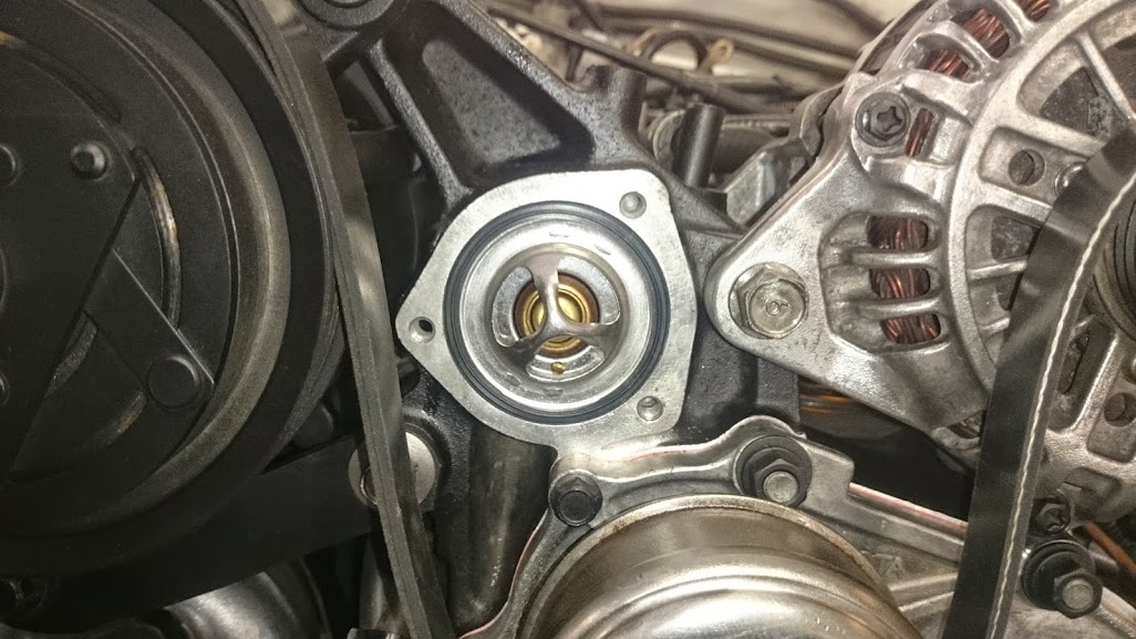
Mazdatrix order arrived, well packed and didnt take that long really however the thermostat with gasket that i ordered did not have a gasket. annoying but i just ordered another from my local mazda parts shop twice the price as listed on mazdatrix but at only $10 still.

So went a ahead and installed the new gaskets and a new shim


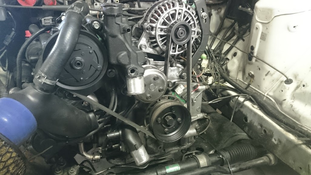
Another milestone moment was having a belt back on the motor again
Another cool little ebay part i found was these battery terminals, makes for adding heavy load circuits very neat!
and really easy to use.


I was actually playing with having the radiator flipped today,
I'll have the whole radiator sitting upside down and back the front, the cap will be cut off and welded.
The IC wont be able to sit in the centre but should hopefully line up better with the turbo outlet and manifold inlet.
Ill attach a bit of right angle aluminium pipe near the top radiator outlet that will then link the bottom outlet to the engine.
This will leave the other side free for the oil hoses and will hopefully line the intercooler outlets up with the motor outlets as i said.
I've got my CAD stuff installed on my laptop soo ill do up some drawings of the proposed setup tomorrow for some pictures.
Now picture updates!
Mazdatrix order arrived, well packed and didnt take that long really however the thermostat with gasket that i ordered did not have a gasket. annoying but i just ordered another from my local mazda parts shop twice the price as listed on mazdatrix but at only $10 still.
So went a ahead and installed the new gaskets and a new shim
Another milestone moment was having a belt back on the motor again
Another cool little ebay part i found was these battery terminals, makes for adding heavy load circuits very neat!
and really easy to use.
Thread Starter
Full Member
Joined: Feb 2011
Posts: 186
Likes: 5
From: Australia
Quick little draft of the V-mount setup.
The green parts are the brackets that will be made,
Also note the 90 elbow which will be supported there aswell,
piping is a rough guide and the bar over the radiator represents the old oil cooler mount bar and support beam.
The front bracket will also function as a skid bar and should protect the radiator reasonably well.
From the front of the car

From the inside the engine bay

The green parts are the brackets that will be made,
Also note the 90 elbow which will be supported there aswell,
piping is a rough guide and the bar over the radiator represents the old oil cooler mount bar and support beam.
The front bracket will also function as a skid bar and should protect the radiator reasonably well.
From the front of the car
From the inside the engine bay
Thread Starter
Full Member
Joined: Feb 2011
Posts: 186
Likes: 5
From: Australia
PARTS!!!!
-10an lines and fittings
an spanner
more electrical connectors
thermostat gasket
heat shrink
dress up bolts

Quick test fit of the fittings on the cooler

Dress up bolt, actually really like them, these were the cheapest i could find on ebay soo i bought a few packs


I've decided i no longer like the green bits in the bay soo im going to give them a red annodized look to match the an plumbing
first little bit ive changed the only problem is this paint requires a lot more prep and a near polished surface

Thermostat installed
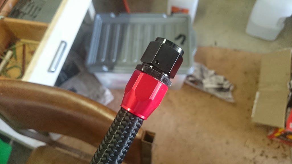
First an fitting installed not bad considering i didnt use a vice and only one aluminium spanner, few little nicks and requires a lot more force then i would have thought
Second

-10an lines and fittings
an spanner
more electrical connectors
thermostat gasket
heat shrink
dress up bolts
Quick test fit of the fittings on the cooler
Dress up bolt, actually really like them, these were the cheapest i could find on ebay soo i bought a few packs
I've decided i no longer like the green bits in the bay soo im going to give them a red annodized look to match the an plumbing
first little bit ive changed the only problem is this paint requires a lot more prep and a near polished surface
Thermostat installed
First an fitting installed not bad considering i didnt use a vice and only one aluminium spanner, few little nicks and requires a lot more force then i would have thought
Second
Thread Starter
Full Member
Joined: Feb 2011
Posts: 186
Likes: 5
From: Australia
More Parts!


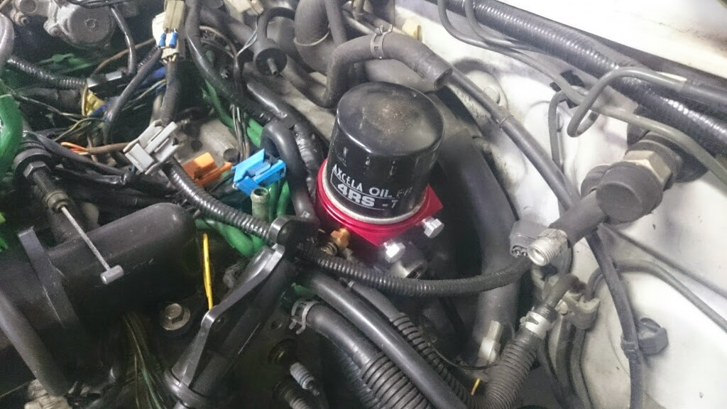
Got a cheap sandwhich plate too, installed.
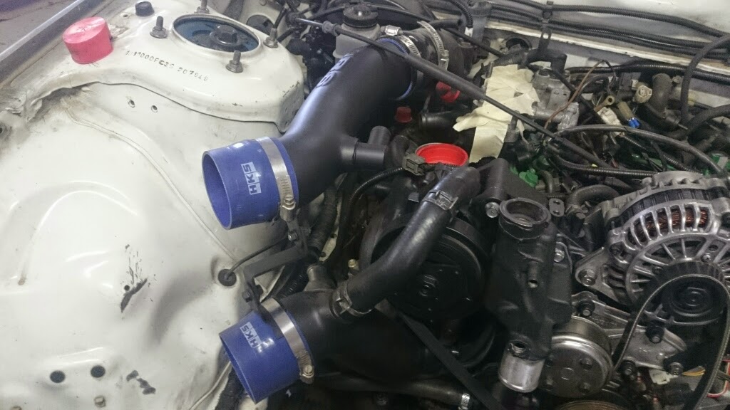
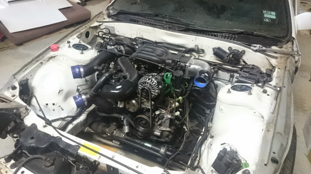
Was finally able to install the top pipe of the HKS intake manifold no pictures to show it but it doesnt look like it'll fit under the bonnet.
ROTARY WORKS IS A JOKE!!!
Have heard terrible things about their products but this one seemed pretty straight forward, intake elbow to suit rew and re intakes, its like they put it on a cosmo and then thought hey lets put a fd plate on it aswell with out even test fitting it!!!
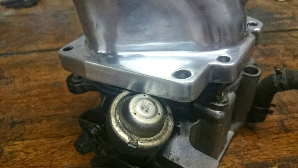

I just removed the throttle dampner, and then took to the water intake with the dia grinder quite a few minutes later came back with this, not really pretty but im happy with the results and still seems quite strong


My new favourite picture! slow progress, is progress!
Got a cheap sandwhich plate too, installed.
Was finally able to install the top pipe of the HKS intake manifold no pictures to show it but it doesnt look like it'll fit under the bonnet.
ROTARY WORKS IS A JOKE!!!
Have heard terrible things about their products but this one seemed pretty straight forward, intake elbow to suit rew and re intakes, its like they put it on a cosmo and then thought hey lets put a fd plate on it aswell with out even test fitting it!!!
I just removed the throttle dampner, and then took to the water intake with the dia grinder quite a few minutes later came back with this, not really pretty but im happy with the results and still seems quite strong
My new favourite picture! slow progress, is progress!
Thread Starter
Full Member
Joined: Feb 2011
Posts: 186
Likes: 5
From: Australia
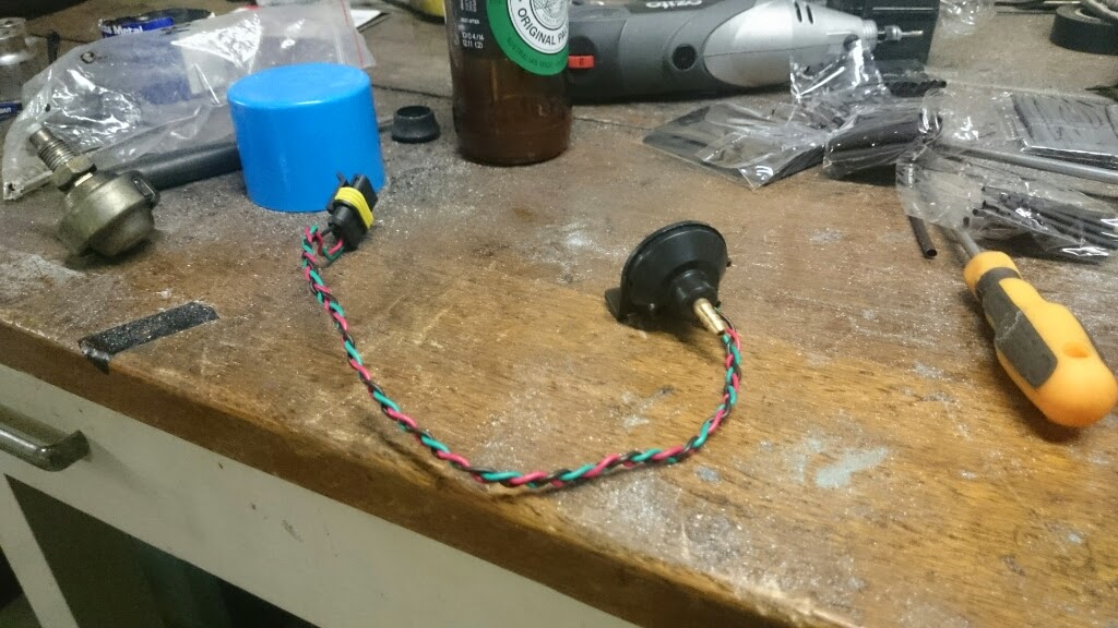
Getting my arts and crafts on, first one wasnt the best should have braided then cut and put the connector on.

Did the pressure sensor too
Gauges Done,


Mounted them on the dash,

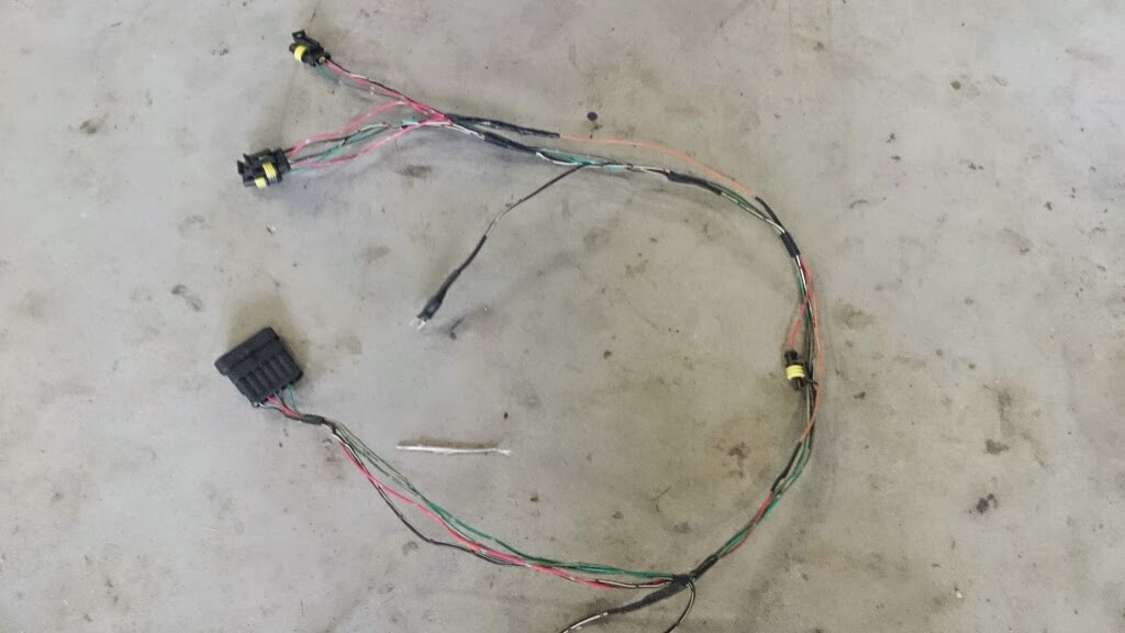
The Interior loom i made for them, one spare signal wire on the connector and several earths. wont wrap it till i get my wideband but have left provisions for it.
Done! for the most part.

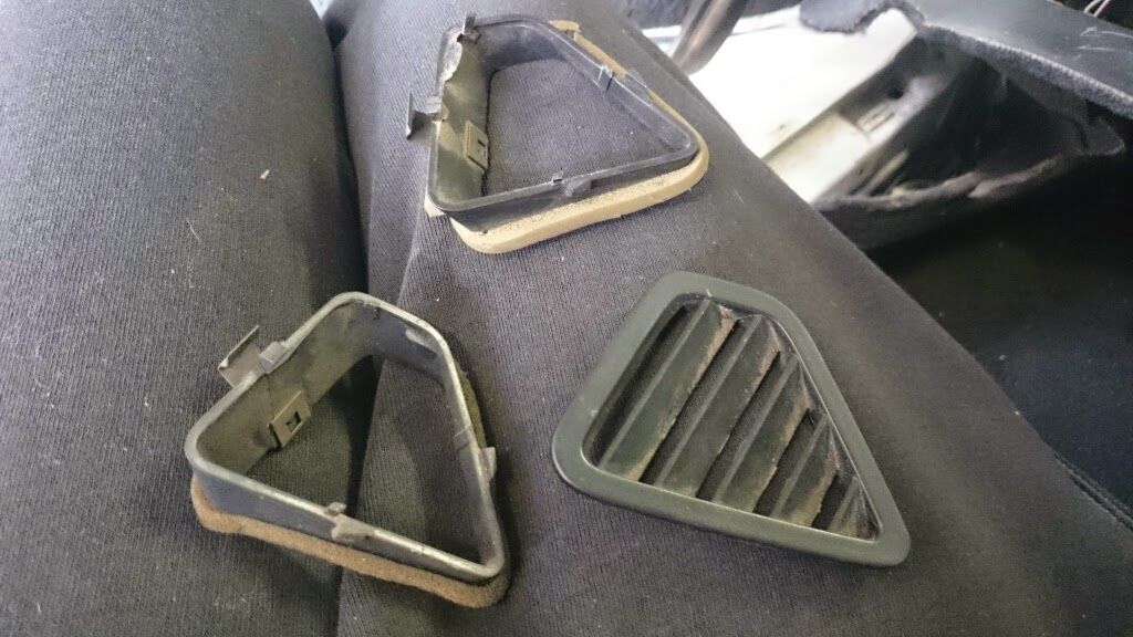
Someone before had thought it must be better to have two sets of clamps for the triangle vents, interesting find.
Did the pressure sensor too
Gauges Done,
Mounted them on the dash,
The Interior loom i made for them, one spare signal wire on the connector and several earths. wont wrap it till i get my wideband but have left provisions for it.
Done! for the most part.
Someone before had thought it must be better to have two sets of clamps for the triangle vents, interesting find.
Thread Starter
Full Member
Joined: Feb 2011
Posts: 186
Likes: 5
From: Australia
finished the intake plumbing,
Lower bov
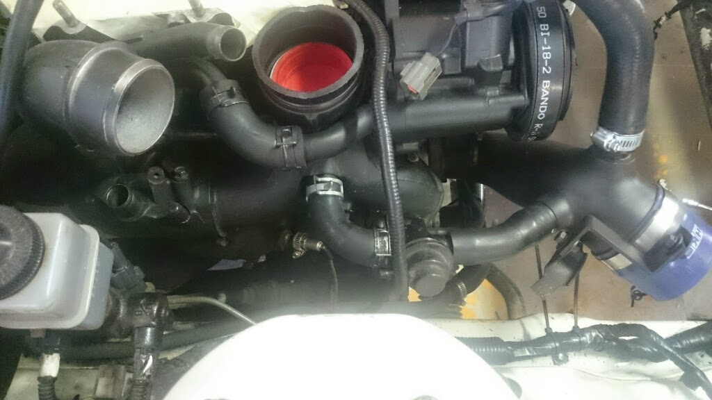
Upper Bov and ACV intake, None of this will be plugged in but for now i want it too look relatively stock

Thats if my bonet closes with this take!
Baby steps

Then Started mocking up the intercooler plumbing, this is roughly where the intercooler will sit, it is off centre to line up with the rotaryworks elbow.

This still leaves room for the oil lines,

And hopefully enough room for both water lines,

Using some poly got a cold side pipe,
The other side is also super simple i just need a right angle piece made up


Added my fans to my drawing if i mount them centered there was barely any clearance, so they will be mounted at the back like so, also added the piping i will need to.

Lower bov
Upper Bov and ACV intake, None of this will be plugged in but for now i want it too look relatively stock
Thats if my bonet closes with this take!
Baby steps
Then Started mocking up the intercooler plumbing, this is roughly where the intercooler will sit, it is off centre to line up with the rotaryworks elbow.
This still leaves room for the oil lines,
And hopefully enough room for both water lines,
Using some poly got a cold side pipe,
The other side is also super simple i just need a right angle piece made up
Added my fans to my drawing if i mount them centered there was barely any clearance, so they will be mounted at the back like so, also added the piping i will need to.
Thread Starter
Full Member
Joined: Feb 2011
Posts: 186
Likes: 5
From: Australia
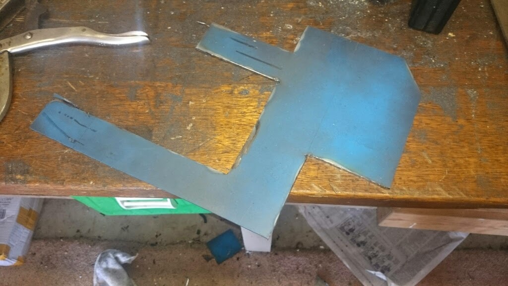
Got sick of waiting for my fabricator soo did my oil cooler brackets myself,
very very crudely

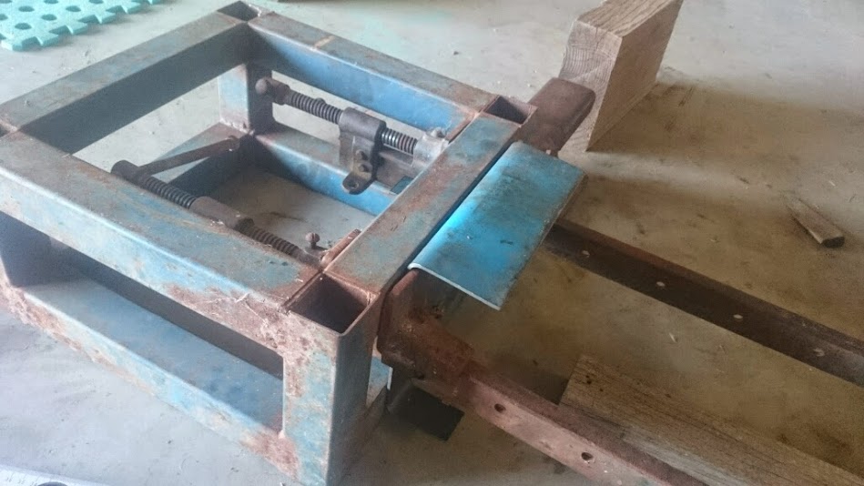
After a bit of bending and cutting got something that resembles a bracket


First set of holes


Was looking good untill

Soo redrilled the holes and cut some off material off the bracket and bam!

Right side bracket painted after some finally trimming


very very crudely
After a bit of bending and cutting got something that resembles a bracket
First set of holes
Was looking good untill
Soo redrilled the holes and cut some off material off the bracket and bam!
Right side bracket painted after some finally trimming
Thread Starter
Full Member
Joined: Feb 2011
Posts: 186
Likes: 5
From: Australia
A better picture of how the mount attaches to the cooler and chassis
Passenger side bracket came up much better and was certainly a lot quicker my grinder skills are getting much better too


Quite pleased with the end result
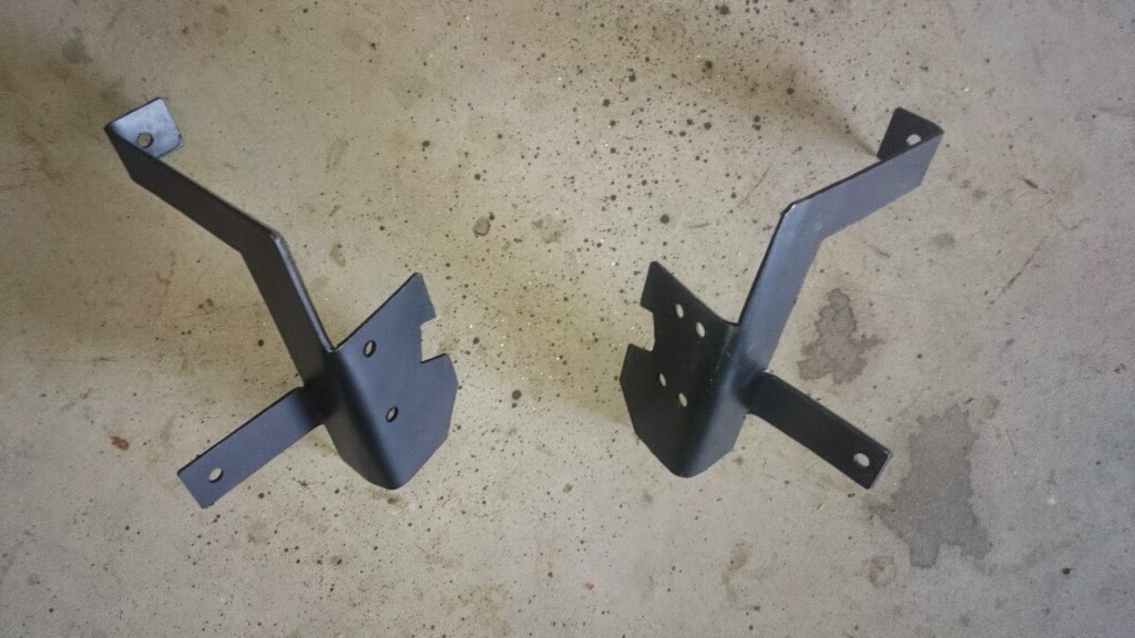
Passenger side bracket came up much better and was certainly a lot quicker my grinder skills are getting much better too
Quite pleased with the end result

Thread Starter
Full Member
Joined: Feb 2011
Posts: 186
Likes: 5
From: Australia
Cheers guys,
Yeah that RS intake is one of my favourite parts i also love how it looks matte black!
This week was meant to see some major devolpements especially with the v mount but i sent my radiator out for mods and the guy is just heaps flakey and taking his time.
Yeah that RS intake is one of my favourite parts i also love how it looks matte black!
This week was meant to see some major devolpements especially with the v mount but i sent my radiator out for mods and the guy is just heaps flakey and taking his time.
Thread Starter
Full Member
Joined: Feb 2011
Posts: 186
Likes: 5
From: Australia
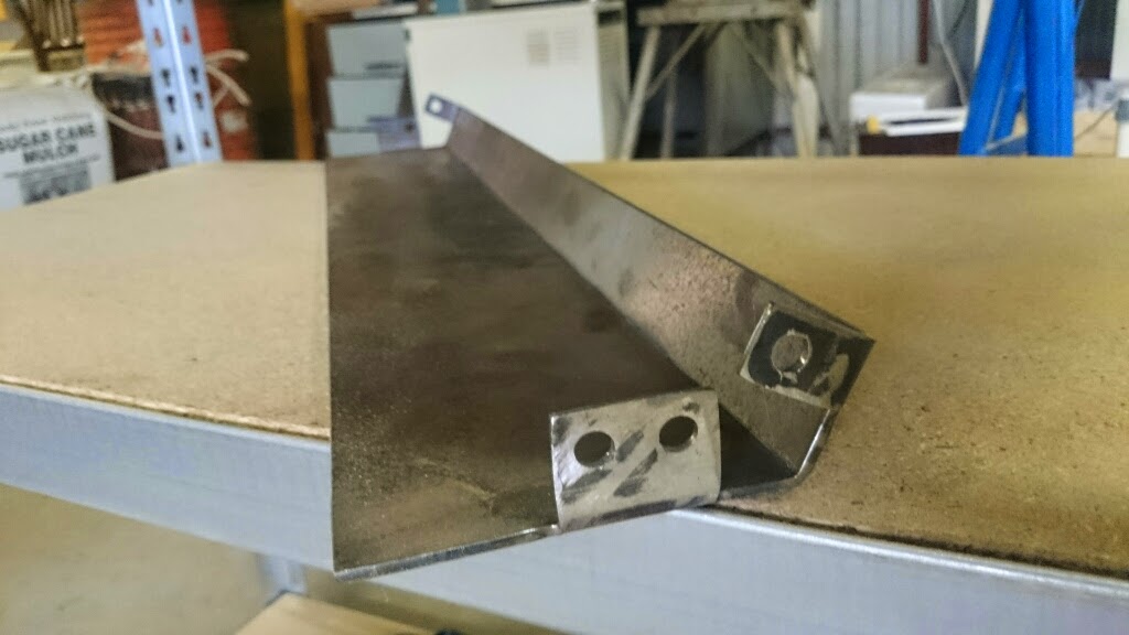
Considering everything i really should have just taught myself to weld along with everything althou i must say i am enjoying trying to devolpe ways that dont require any welding and can be bolted on and off at anytime.
I've got my radiator off in a shop getting fabricated at the moment, the cap cutoff and shut and some threaded bungs put on the side.
I also have a new design for the mounts that wont require any welding.
Once measured ill get an engineering place to bend the main support/bash plate its quite long and im guessing ill want 5+mm thick steel ie not something i can do myself
the red part of the mount will be added later by a welder and will support the radiator from horizontal movement. this is also where and how itll attach to the chassis

This also happened a while back now,

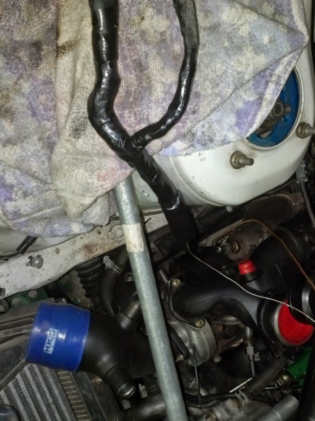
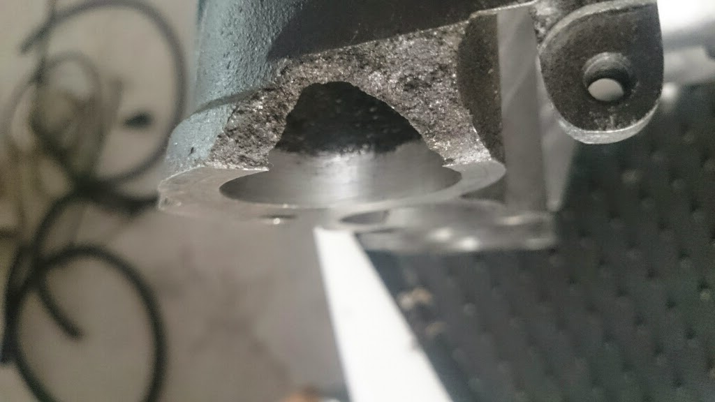
It wasnt me if you look closely in this photo you can see the black carbon built up along the fault, and then shinier 1mm area along the flang was the only thing still holding it together. costly but at least i found it now would have been a **** vaccum leak to try and find later.
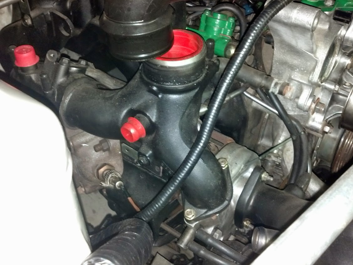
While the manifold was off again decided id clean it up a little again and remove the hard fuel lines as the routing of the wiring loom goes in between them highly annoying.

Didnt take any pictures but ported and removed the secondary butterflies again, and put her back together and looking purdy...

I've got my radiator off in a shop getting fabricated at the moment, the cap cutoff and shut and some threaded bungs put on the side.
I also have a new design for the mounts that wont require any welding.
Once measured ill get an engineering place to bend the main support/bash plate its quite long and im guessing ill want 5+mm thick steel ie not something i can do myself
the red part of the mount will be added later by a welder and will support the radiator from horizontal movement. this is also where and how itll attach to the chassis
This also happened a while back now,
It wasnt me if you look closely in this photo you can see the black carbon built up along the fault, and then shinier 1mm area along the flang was the only thing still holding it together. costly but at least i found it now would have been a **** vaccum leak to try and find later.
While the manifold was off again decided id clean it up a little again and remove the hard fuel lines as the routing of the wiring loom goes in between them highly annoying.
Didnt take any pictures but ported and removed the secondary butterflies again, and put her back together and looking purdy...
Thread Starter
Full Member
Joined: Feb 2011
Posts: 186
Likes: 5
From: Australia
Well first up picked up my main radiator support the other day, looks mint.

Got an ebay spec nutsert tool,

So converted my oil cooler brackets... Sooo Much better!

Was still waiting on getting the radiator back soo painted the brakes, not sure i like the red thou.

Slotted rotors and definately happening soon!


Got an ebay spec nutsert tool,
So converted my oil cooler brackets... Sooo Much better!
Was still waiting on getting the radiator back soo painted the brakes, not sure i like the red thou.
Slotted rotors and definately happening soon!
Thread Starter
Full Member
Joined: Feb 2011
Posts: 186
Likes: 5
From: Australia
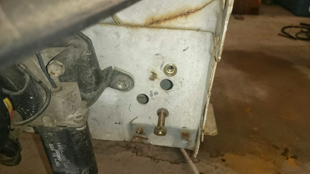
Found this hilarious mod,

And did the relay mod to my power windows well the driver anyway i have an issue with power not getting to the other door. guide i used from hereFC3S Power Window Relay Mod
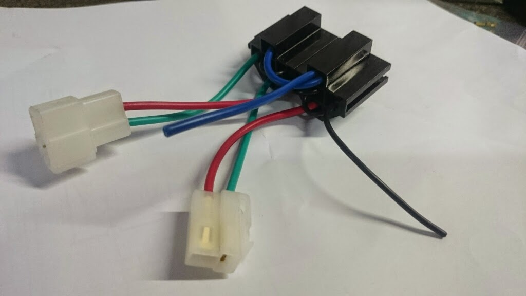

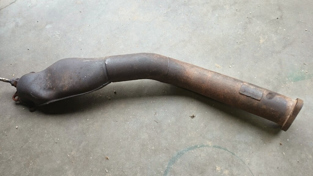
And picked up a 3" downpipe never heard of the brand but was nice and cheap all thou looks like the turbo mount will need a linish

And did the relay mod to my power windows well the driver anyway i have an issue with power not getting to the other door. guide i used from hereFC3S Power Window Relay Mod
And picked up a 3" downpipe never heard of the brand but was nice and cheap all thou looks like the turbo mount will need a linish
Thread Starter
Full Member
Joined: Feb 2011
Posts: 186
Likes: 5
From: Australia
Got the radiator back finally!!!!
Bungs added to the side of the tanks

And the cap cut and welded

Some more hammer time got me this far then i screwed up one of the nutserts and now im trying to work out how to get that off or something....

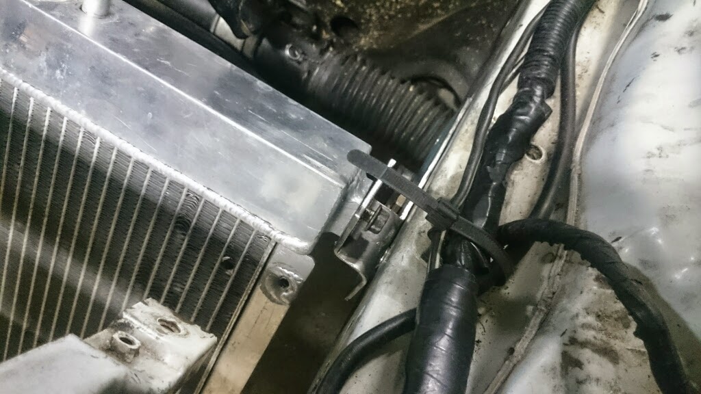
Unfortunately now im back at work soo could be a while inbetween updates again...
Bungs added to the side of the tanks
And the cap cut and welded
Some more hammer time got me this far then i screwed up one of the nutserts and now im trying to work out how to get that off or something....
Unfortunately now im back at work soo could be a while inbetween updates again...
Joined: Mar 2001
Posts: 31,851
Likes: 3,239
From: https://www2.mazda.com/en/100th/
i noticed that the FD vacuum rack is actually bolted together, so if you wanted, you can just have the fuel line part, and the rest goes away. which is neat.