4-Rotor FC Build


Rotary Enthusiast
Joined: Aug 2008
Posts: 1,101
Likes: 13
From: Portsmouth UK
Good Work. not sure I have followed what you are going to do with the inner seals near the chamber to make them hard wearing and more resistant to the pressure but I am kean to see as I have thought about doing exactly this for my triple rebuild when I strip it. The only bit I was concerned about was being able to get a complete ring the right size off the shelf and if not how to join and make one without risk of it failing?! Seems like you might answer some of my questions. I can possibly even get some better gasket than viton through some of my work contacts. I cannot see any reason why this should not work and why Mazda chose to make such a specific seal? Is you o-ring a round or square section by the way? hard to tell in the pictures. personally I would go with square I think?
Thread Starter
Joined: Oct 2010
Posts: 605
Likes: 13
From: The Netherlands
You need to read this front-to-back
https://www.rx7club.com/rotary-car-p...ng-kit-626610/
Oh, and this:
AusRotary.com • View topic - Sick of gettin jipped on O'Rings!!
You won't be able to get a complete ring right off the shelf in the correct size. No worries, if you use the right glue to join them the joint will be far stronger than the joint on the stock mazda seals. I tested it, and the joint is actually even stronger than the rubber itself. The o-ring I used has a round section. The roundness allows the o-ring to be squished into a square when the engine is tightened, it's how o-rings seal. I'd be worried about collapsing coolant walls when using square rings. Also watch out with using 'better than viton' seals. One seal material is seldom 'better' than the other one, it depends on the application if one seal material is 'better' than the other one. NBR often seals better than viton, but it's not as temperature resistant, hence the need to use viton as inners.
Wasted spark plug
Joined: May 2012
Posts: 64
Likes: 0
From: Enschede, The Netherlands
About the worry John is taking risk by doing it his own way, I don't think John is creating a production engine that has to last 100.000+ miles to keep customers happy like Mazda has to.
I think common technical sense, skills, a budget and some boldness makes this project so much fun to follow.
Keep up the good work!
Excellent topic!
Grtz Dennis.
I think common technical sense, skills, a budget and some boldness makes this project so much fun to follow.
Keep up the good work!
Excellent topic!
Grtz Dennis.

Senior Member


Joined: Aug 2010
Posts: 415
Likes: 8
From: Treasure coast
"...Also got the seals for the irons ready, I'm using viton o-rings here instead of the stock mazda seals. Got a bunch of 2.4 and 2.0 viton cord through an industrial supplier, cut everything to size and joined the seals with sicomet."
did you put an angle cut (e.g., 45deg) on the ends for more surface adhesion area?
did you align the ends by eyeball?
special steps required when gluing together?
will you supplement the seals with a sealant of some type during engine assembly?>
did you put an angle cut (e.g., 45deg) on the ends for more surface adhesion area?
did you align the ends by eyeball?
special steps required when gluing together?
will you supplement the seals with a sealant of some type during engine assembly?>
Rotary Enthusiast
Joined: Aug 2008
Posts: 1,101
Likes: 13
From: Portsmouth UK
Thanks for the info John, I will check out those links.As for further questions so far exactly what he said above.. I was mainly wondering about the alignment.. Did you make a little jig?
I thought a square seal would seal better due to contact surface area surely being larger? Evening allowing for squash on a round section? the material I was looking at is used on F1 oil tank seals. All I know at present is it is a pale green colour. Need to find out more!
I thought a square seal would seal better due to contact surface area surely being larger? Evening allowing for squash on a round section? the material I was looking at is used on F1 oil tank seals. All I know at present is it is a pale green colour. Need to find out more!
Thread Starter
Joined: Oct 2010
Posts: 605
Likes: 13
From: The Netherlands
"...Also got the seals for the irons ready, I'm using viton o-rings here instead of the stock mazda seals. Got a bunch of 2.4 and 2.0 viton cord through an industrial supplier, cut everything to size and joined the seals with sicomet."
did you put an angle cut (e.g., 45deg) on the ends for more surface adhesion area?
did you align the ends by eyeball?
special steps required when gluing together?
will you supplement the seals with a sealant of some type during engine assembly?>
did you put an angle cut (e.g., 45deg) on the ends for more surface adhesion area?
did you align the ends by eyeball?
special steps required when gluing together?
will you supplement the seals with a sealant of some type during engine assembly?>
Ok, this is how I made the o-rings:
- Checked what o-rings I needed, 2.0mm round viton cord for the outer ring, 7,5 metres for 4-rotor, 2.4mm round viton cord for the inner ring, 6 metres.
- Called the o-ring guy, ordered seals, waited a day, gave the o-ring guy money, recieved the seals
- Made sure o-ring grooves in irons are super clean
- Put o-rings in grooves, marked where to cut the seals using masking tape. Cut the cord a little on the longer side, so that it sits on the outside of the o-ring groove. (This wil make sure that the joint is pushed together when the tension bolts are tightened, which is good).
- Cut the cords to size using a really really sharp snip, paying attention to cutting it straight (no 45 degree, just straight)
- Used this little guy to align the cord ends:

Put the cord ends in, lock it using the clamps, check if the seal is aligned perfectly
- Used a teeny tiny dab of sicomet 8300, it's very easy to use too much.
- Released the lever on the tool, which presses the ends together using the spring
- Waited one minute
And done, nicely joined o-rings
 , Took me 2 lazy hours to do all the seals for my engine. Yes, I plan on using sealant with the o-ring. I think a teeny tiny bit of locktide 5366 between the groove and the o-ring will work well. And then a little bit of hylomar on the rotor housing, with locktide 5926 on the legs.
Thanks for the info John, I will check out those links.As for further questions so far exactly what he said above.. I was mainly wondering about the alignment.. Did you make a little jig?
I thought a square seal would seal better due to contact surface area surely being larger? Evening allowing for squash on a round section? the material I was looking at is used on F1 oil tank seals. All I know at present is it is a pale green colour. Need to find out more!
I thought a square seal would seal better due to contact surface area surely being larger? Evening allowing for squash on a round section? the material I was looking at is used on F1 oil tank seals. All I know at present is it is a pale green colour. Need to find out more!
Thread Starter
Joined: Oct 2010
Posts: 605
Likes: 13
From: The Netherlands
Dumped some more time into the car last weekend. Started out preparing everything for engine assembly. Still had to make some assembly tools, like a piece to hold the e-shaft stationairy when torquing the counterweight nut, and I made a piece which I could use for making timing marks. Also had to fabricate an engine stand.
After that was done I made something to check the rear pressure regulators I had. I found 3 regulators, but it's impossible to see their relieve pressures from the outside, so I made a tool and checked with compressed air.
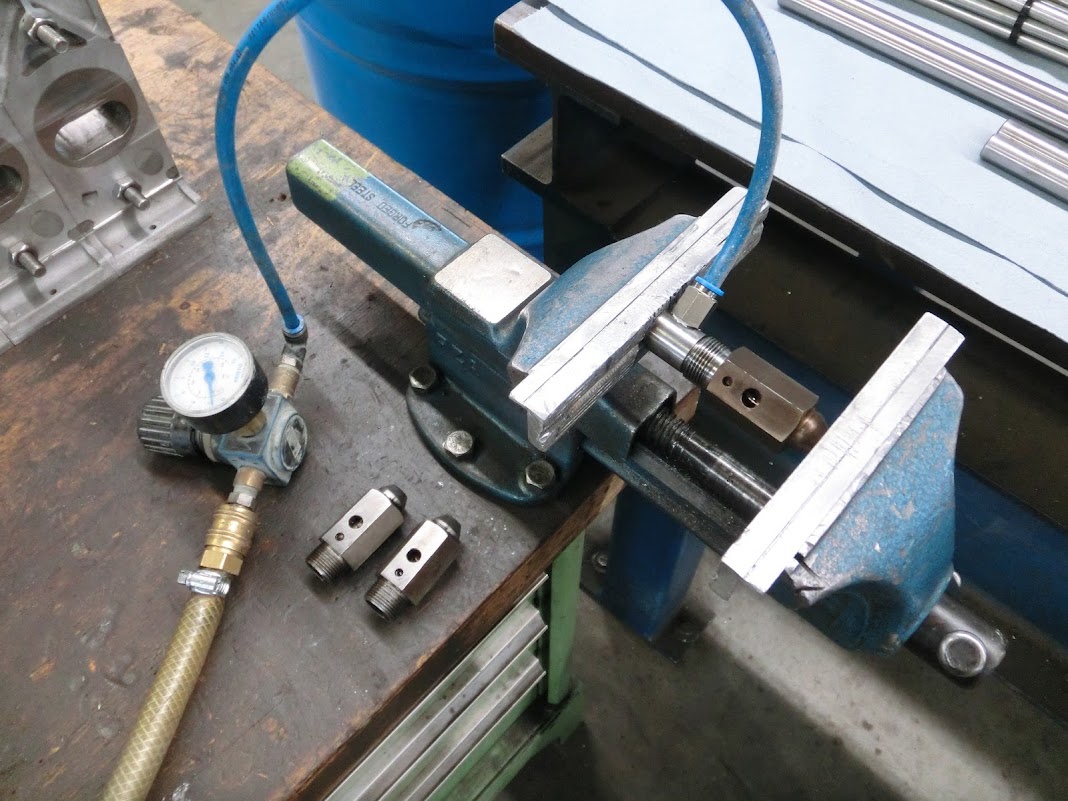
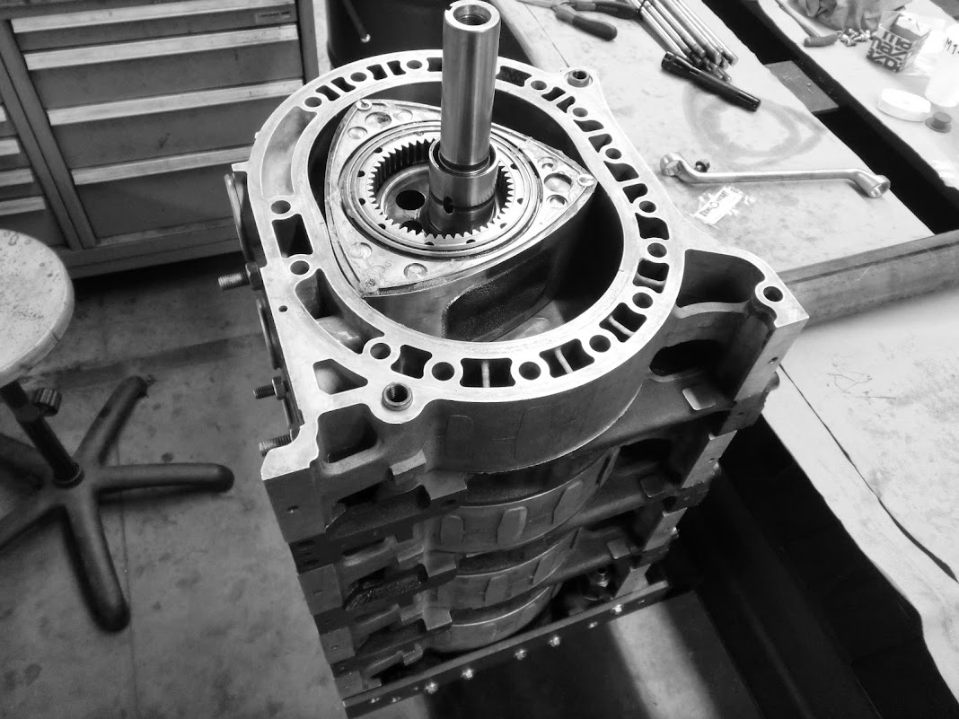
2 started opening at 4 bars, probably FC units, one opened at about 7 bars, so probably an FD one. I used the FD one. After that was done I started with the engine bearings. New main bearings were pressed in and clearanced to about 0,09mm, Rotor bearings were also clearanced. Then I gave everything a last good clean, especially the water seal grooves. At that time my working place looked like this:

I'm assembling the engine rear-to-front. This will allow me to add timing marks accurately on the flywheel as I go. You can see the bearing is copper coloured, this is caused by clearancing. Unmodified clearance was about 0,06mm, so too little for this engine.

The rotor back in it's home , you can see that the rotor has been side-clearanced. The side-clearancing removed the numbers to tell you where to put each side-seal. Normally you can just look at the other side to tell you which number used to go where, but this isn't possible during assembling, so mark them! Found that one out the hard way

There, everything in place
Note the use of long solid dowels. These go from the back of the engine all the way to the center of the intermediate iron between rotor 1 and 2. Normal dowels will go in front of these. These dowels are an attempt to stiffen up the long engine a little bit because long 4-rotor can flex a little bit. Probably won't solve it, but making them solid also prevents the engine bay to be covered in oil should the rear iron crack. I don't need them for delivering oil to the stationairy gears anyway, they all got an independent external oil feed. These dowels do make engine assembly a bit difficult. It's necessary to temporarely remove the e-shaft, put it in the intermediate iron, and slide the iron with the e-shaft in it over the dowels.

So, up to that point everything was coming together nicely. Everything looked good, that is untill I tried putting the e-shaft in the intermediate iron. As I slid the e-shaft in there I heard a metallic 'tak' and saw the e-shaft touching the iron, not willing to go in. I looked some more, but there was no way around it. The piece between the rotor 1-2 and 3-4 lobes is machined a tiny bit too thick. I was and still am completely baffled and shocked that I managed to screw that one up! When I thought of it, I really never tried to fit in in there, I just never really thought about that not fitting. When drawing up the e-shaft in CAD I did a quick check on the computer, and thought that it could go in, but I was wrong. So that really put an end to assembling the engine, it's just impossible to get the e-shaft through the intermediate iron making it impossible to assemble the engine. It's kindoff silly to think that I spend all that time and effort into making absolutely sure that all the e-shaft's tolerances and specs are absolutely top notch bang-on perfect, but then completely overlooked the fact that it does not fit.

So I hit myself in the head a few times for making such a stupid mistake, disassembled the part of the engine that was together at that point, cleaned all the parts and grooves while the sealant still wasn't cured yet, and then went out and got really drunk.
Today I started fixing the issue. A normal e-shaft is about 70mm's thick between the lobes, mine was a little bit bigger, in order to make it more rigid. (Comparing picture here: https://lh4.googleusercontent.com/-F...8/CIMG1388.JPG)
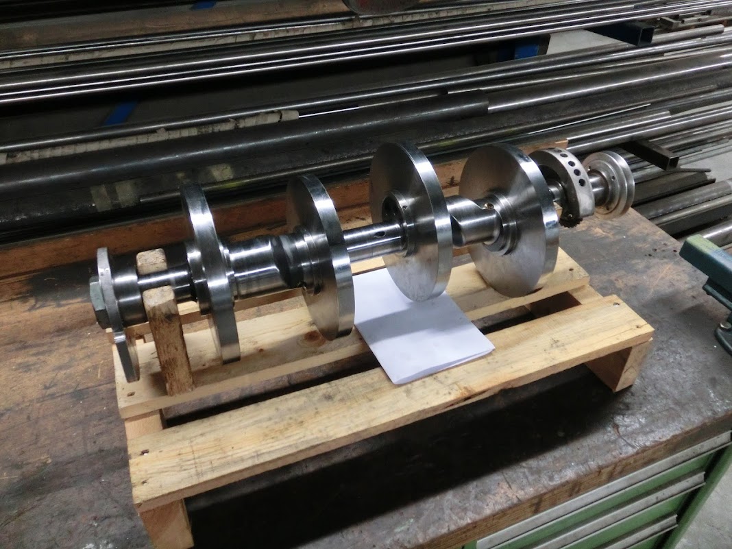
I just machined my e-shaft down a little bit to the same 70mm, and now it does fit. I was too hungover to make any pictures, but it was a pretty basic lathe operation. No further issues with the e-shaft, but the crappy part is that this does affect the engine balancing that has been done .
.
I got the corrected e-shaft together with the bob and counterweights and will be taking it to the shop that did the balancing tomorrow, to get the balance checked and corrected.
So yeah, this weekend really sucked. But I'm pretty confident that the next attempt to assembling the engine will be more succesfull , I'll get there one day!
After that was done I made something to check the rear pressure regulators I had. I found 3 regulators, but it's impossible to see their relieve pressures from the outside, so I made a tool and checked with compressed air.
2 started opening at 4 bars, probably FC units, one opened at about 7 bars, so probably an FD one. I used the FD one. After that was done I started with the engine bearings. New main bearings were pressed in and clearanced to about 0,09mm, Rotor bearings were also clearanced. Then I gave everything a last good clean, especially the water seal grooves. At that time my working place looked like this:
I'm assembling the engine rear-to-front. This will allow me to add timing marks accurately on the flywheel as I go. You can see the bearing is copper coloured, this is caused by clearancing. Unmodified clearance was about 0,06mm, so too little for this engine.
The rotor back in it's home
, you can see that the rotor has been side-clearanced. The side-clearancing removed the numbers to tell you where to put each side-seal. Normally you can just look at the other side to tell you which number used to go where, but this isn't possible during assembling, so mark them! Found that one out the hard wayThere, everything in place
Note the use of long solid dowels. These go from the back of the engine all the way to the center of the intermediate iron between rotor 1 and 2. Normal dowels will go in front of these. These dowels are an attempt to stiffen up the long engine a little bit because long 4-rotor can flex a little bit. Probably won't solve it, but making them solid also prevents the engine bay to be covered in oil should the rear iron crack. I don't need them for delivering oil to the stationairy gears anyway, they all got an independent external oil feed. These dowels do make engine assembly a bit difficult. It's necessary to temporarely remove the e-shaft, put it in the intermediate iron, and slide the iron with the e-shaft in it over the dowels.
So, up to that point everything was coming together nicely. Everything looked good, that is untill I tried putting the e-shaft in the intermediate iron. As I slid the e-shaft in there I heard a metallic 'tak' and saw the e-shaft touching the iron, not willing to go in. I looked some more, but there was no way around it. The piece between the rotor 1-2 and 3-4 lobes is machined a tiny bit too thick. I was and still am completely baffled and shocked that I managed to screw that one up! When I thought of it, I really never tried to fit in in there, I just never really thought about that not fitting. When drawing up the e-shaft in CAD I did a quick check on the computer, and thought that it could go in, but I was wrong. So that really put an end to assembling the engine, it's just impossible to get the e-shaft through the intermediate iron making it impossible to assemble the engine. It's kindoff silly to think that I spend all that time and effort into making absolutely sure that all the e-shaft's tolerances and specs are absolutely top notch bang-on perfect, but then completely overlooked the fact that it does not fit.
So I hit myself in the head a few times for making such a stupid mistake, disassembled the part of the engine that was together at that point, cleaned all the parts and grooves while the sealant still wasn't cured yet, and then went out and got really drunk.
Today I started fixing the issue. A normal e-shaft is about 70mm's thick between the lobes, mine was a little bit bigger, in order to make it more rigid. (Comparing picture here: https://lh4.googleusercontent.com/-F...8/CIMG1388.JPG)
I just machined my e-shaft down a little bit to the same 70mm, and now it does fit. I was too hungover to make any pictures, but it was a pretty basic lathe operation. No further issues with the e-shaft, but the crappy part is that this does affect the engine balancing that has been done
.I got the corrected e-shaft together with the bob and counterweights and will be taking it to the shop that did the balancing tomorrow, to get the balance checked and corrected.
So yeah, this weekend really sucked. But I'm pretty confident that the next attempt to assembling the engine will be more succesfull
Thread Starter
Joined: Oct 2010
Posts: 605
Likes: 13
From: The Netherlands
Already did the machining, no re-nitrating is necessary. You can actually see the part that I machined at the previous pictures, note that 3 photos up the piece between the rotor 3 and 4 lobes is still black, and in the last picture with the bob weights that piece is now machined-blank. By machining it I did remove the hard layer, but it doesn't touch anything so it doesn't need to be hard. OEM shafts aren't hardened here also. The e-shaft is still a bit more beefy than stock, and it's made from a superior metal alloy, so I'm not worried about it's strength.
I just dropped the rotating assembly off at the driveshaft shop that does balancing, they were cool about it, said they'd help me out and try to get it checked out before the weekend so fingers crossed!, Also ordered some new o-rings, to replace the ones I already had in there during the first assembly attempt. I could probably re-use them, especially since they hadn't been in a torqued down engine yet, but I don't want to take any chances and o-rings are dirt cheap
I just dropped the rotating assembly off at the driveshaft shop that does balancing, they were cool about it, said they'd help me out and try to get it checked out before the weekend so fingers crossed!, Also ordered some new o-rings, to replace the ones I already had in there during the first assembly attempt. I could probably re-use them, especially since they hadn't been in a torqued down engine yet, but I don't want to take any chances and o-rings are dirt cheap
Junior Member
Joined: Apr 2012
Posts: 2
Likes: 0
From: France
Hello John
I follow your post from France since a couple of years
My actual job is Lean Manufacturing in a aeronautical composites parts factory
I want to send you this message asa I see Your Workspace so Clean in your next pictures,!
Great Respect !!
Sure you will next succeed to start this engine and hope i can see it in Netherlands or France maybe
all the Best
Michel

Thread Starter
Joined: Oct 2010
Posts: 605
Likes: 13
From: The Netherlands
Yes, it would be a lot simpler! And it is possible to make that hole a few mm's larger before running into oil control ring issues. It couldn't be made big enough for the e-shaft to fit though, so I had to modify the shaft.