
4-Rotor FC Build

Thread Starter
Joined: Oct 2010
Posts: 605
Likes: 13
From: The Netherlands
Picture of the shell, it actually still has a complete running turbo engine in it  The BMW behind it is my daily mule. It carries me and my rotary parts around town.


I finished boring the balancing holes today. After that was done I started on drilling oilchannels. These will be different than in a normal shaft. A normal shaft has a long hole in the center that carries oil. Mine won't have that, but will have cross-drilled oil channels instead.

Downsides are that you can't use the thermal pallet in the front and if one main bearing oil supply fails the corresponding rotor(s) also run out of oil. Not that any of those things matter, I'm not using a thermal pallet anyway and if your main bearings stop getting oil the engine will be toast anyway. The inertia will be a tiny bit higher though .
.
Upsides is that the shaft will be a bit stronger, and should flex a little bit less. The oil that the rotors will get will also be a bit cooler since the path the oil has to travel is shorter and with less 90� bends. Also I'm actually able to fabricate this, I can't drill a 26" long hole.
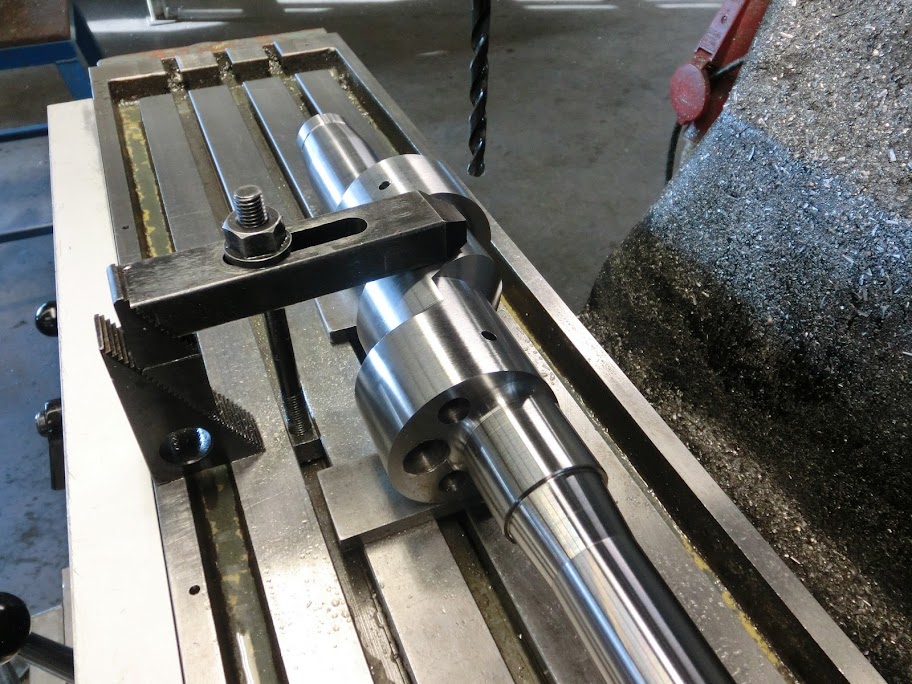
First job was positioning the shaft in the mill

Then I drilled 2 of the oilchannels
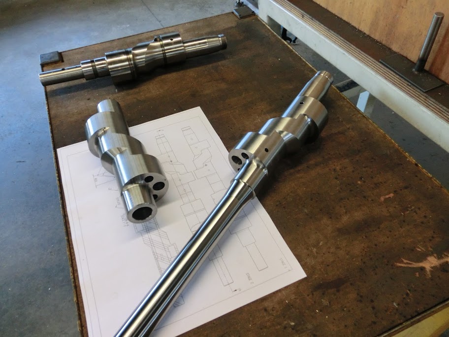
These parts look more like an 4-rotor shaft every day
I'll do some more channels soon.
Some of your questions answered:
I'm still thinking about how I'm going to do the center stat gear plate. I've got an idea though. My center plate will be different than almost all other 4-Rotors, I'm going to have 2 stat gears on one plate. My engine is like 2 engines stuffed together, where as a normal 4-rotor is like one engine with half an engine stuffed to the front and half an engine stuffed to the back. I've thought a lot about both designs, and there are pro's and cons about each design. My design is stronger in the rear part of the engine, but I've only got 3 main bearings, a normal 4-rotor has 4 bearings.
What more OE parts do you want to adapt? I hope you're not talking about the eccentric shaft
Don't know yet, I hope the firewall won't have to be modified too much, but I'll probably have to move the engine backwards a bit, change the engine mounts and shorten the driveshaft. I'll know when I start putting the engine in the car 
I'm planning to get the car running with a normal S4 TII tranny and diff. I've got a few spares of those lying around When I start breaking a lot of drivetrain stuff I'll go look for alternatives, but I'm a long way from that.
The steel I used for the shaft is 34CrNiMo6+QT, it's probably called SAE4340 over there. It's oil hardening, but I'm not going to harden it. I'm going to get it nitrated. It will have to be annealed and re-machined before that though.
Yes, but it's more complicated than that. The holes were machined to be a tight fit with the inserts. Then the inserts were made and smeared in with defcon epoxy and gently tapped in with a nylon hammer. Finally the stainless steel inserts were welded to the liner. I welded them very lightly with tig to avoid warping and messing up the chrome. The inserts actually aren't welded to the chrome surface. The liner is a regular steel liner with a thin chrome layer. You weld the insert to the steel. Afterwards I finished it with a regular dremel.
The BMW behind it is my daily mule. It carries me and my rotary parts around town.I finished boring the balancing holes today. After that was done I started on drilling oilchannels. These will be different than in a normal shaft. A normal shaft has a long hole in the center that carries oil. Mine won't have that, but will have cross-drilled oil channels instead.
Downsides are that you can't use the thermal pallet in the front and if one main bearing oil supply fails the corresponding rotor(s) also run out of oil. Not that any of those things matter, I'm not using a thermal pallet anyway and if your main bearings stop getting oil the engine will be toast anyway. The inertia will be a tiny bit higher though
.Upsides is that the shaft will be a bit stronger, and should flex a little bit less. The oil that the rotors will get will also be a bit cooler since the path the oil has to travel is shorter and with less 90� bends. Also I'm actually able to fabricate this, I can't drill a 26" long hole.
First job was positioning the shaft in the mill
Then I drilled 2 of the oilchannels
These parts look more like an 4-rotor shaft every day
I'll do some more channels soon.
Some of your questions answered:
What more OE parts do you want to adapt? I hope you're not talking about the eccentric shaft
I'm planning to get the car running with a normal S4 TII tranny and diff. I've got a few spares of those lying around
Yes, but it's more complicated than that. The holes were machined to be a tight fit with the inserts. Then the inserts were made and smeared in with defcon epoxy and gently tapped in with a nylon hammer. Finally the stainless steel inserts were welded to the liner. I welded them very lightly with tig to avoid warping and messing up the chrome. The inserts actually aren't welded to the chrome surface. The liner is a regular steel liner with a thin chrome layer. You weld the insert to the steel. Afterwards I finished it with a regular dremel.


Originally Posted by John Huijben
The steel I used for the shaft is 34CrNiMo6+QT, it's probably called SAE4340 over there. It's oil hardening, but I'm not going to harden it. I'm going to get it nitrated. It will have to be annealed and re-machined before that though.

my drawings appear similar to your setup with the exception that the shafts will be keyed and splined between the 2 center bearings creating a simple, short 26B platform with the same bearing loading as this version.
while i do like the idea of removable lobes, most of the time spent on building the 26B is directly spent on manufacturing the eccentric shaft and balancing the rotating assembly. although with the mentioned method it would have to have custom counterweights built as well.
one of the pros to this method is that you can actually remove and reclock the engine to run either 90 degree phasing for top end performance or 2 rotor phasing for torque. it just would require 2 sets of counterweights and a few hours tearing the engine apart to readjust the engine timing.
don't overthink the ability of the eccentric shaft to be able to hold the power, i don't expect that even a keyed split shaft to have any issues holding 550 naturally aspirated horsepower. so long as the retaining method holds up. (going turbo and expecting it to hold 1500 though is a different story)
for the center support bearing/stat gear i plan to mill down 2 stat gears, press them into a sleeve, weld/machine/anneal the assembly, drill the oil drain holes and pin/circlip it to the center iron.
Last edited by RotaryEvolution; Oct 29, 2011 at 04:40 PM.
Thread Starter
Joined: Oct 2010
Posts: 605
Likes: 13
From: The Netherlands
Well you can't build the coupling like they did at grann�'s. Your coupling would be a lot smaller because it has to fit within a main bearing. I wonder how you're planning to tighten the 2 shafts together, a long bolt through the center of the front shaft? Would be great if it works, very cost efficient for sure. I'll have to see it to believe it though, I looked into it a lot, did the math and considered it to weak to be of use. Mazda tried the same with the 2002 4-Rotor and also considered it to weak, and this was with 180hp and a wider center housing to accomodate a wider coupling. Not saying it wouldn't work though, I've seen more designs fail on paper and work in real life. I'm not completely with you on the 90� vs 180� firing order though. I think both firing orders will have about the same amount of torque and top end power. Please keep me updated on this, interesting stuff.
Senior Member
Joined: Nov 2008
Posts: 357
Likes: 0
From: Czech republic
I wonder how you're planning to tighten the 2 shafts together, a long bolt through the center of the front shaft? Would be great if it works, very cost efficient for sure. I'll have to see it to believe it though, I looked into it a lot, did the math and considered it to weak to be of use. Mazda tried the same with the 2002 4-Rotor and also considered it to weak, and this was with 180hp and a wider center housing to accomodate a wider coupling.
http://rides.webshots.com/album/552826780uXOXhl
Check these links. There are photos and informations on how they coupled their shaft. Its been awhile since I read it, but IIRC they had issues with bolt failing and overally with short life of such arrangement.

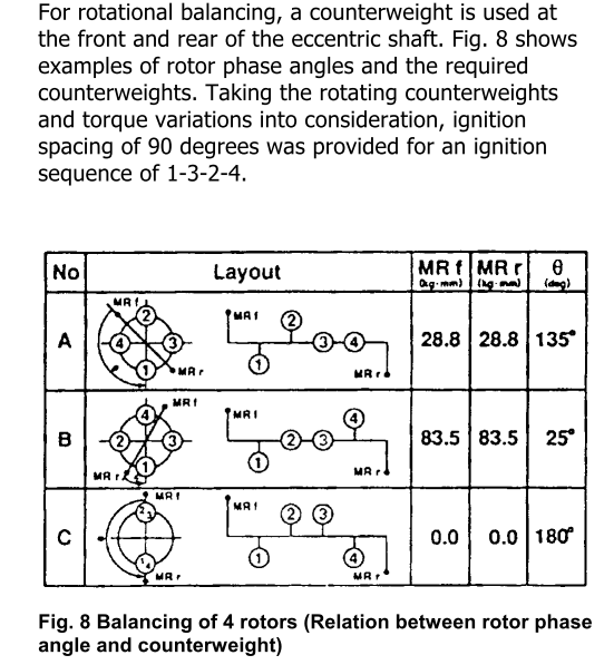
Speaking of firing order and balancing (maybe you discussed it and I missed it), are you doing the same approach Mazda used on the R26B (787B engine)? 90 degree, 1-3-2-4?
for reference:
for reference:


i'd have to guess the main reason it worked well for Granny's was that their design retained front and rear balancing of each half of the engine. for the center section to take the least amount of abuse both e-shafts would have to be clocked in a TDC, 180, TDC, 180 firing order to keep the loading offset at each point in the engine. ideally an internal balancer could be used but that is near impossible without recasting a specialized center iron and figuring out a new way of assembly.
Thread Starter
Joined: Oct 2010
Posts: 605
Likes: 13
From: The Netherlands
I drilled the rest of the oilchannels in the front part of the e-shaft. The channels are a bit larger than in the stock shaft. The rotor bearing channels are �6,5mm, the crossdrilled oil supply channels are �7mm
The threaded part is for the rotor spraying jet. I'm planning on using regular keihin carburettor jets. They are cheap and easy to get in the exact dimension you want.


Feedback to your reply's:
Yes, it's used to give motorbikes more traction, the longer period between pulses created by the firing cylinders gives the tire time to actually regain grip between 2 cylinders firing. I saw a 4 cylinder inline 4 stroke engine a while ago that was converted to a big bang firing order (firing 2 cylinders at once) by cutting the camshaft in half, rotating one piece 180�, and welding it back together. It was difficult to start, but ran well and sounded like a heavy 2 cylinder that could rev a lot higher than all the other 2 cylinder bikes. I'm pretty into bikes, raced a 2-stroke on the track for a while. This is me last year:

The firing order I use is no. A which is the same the 787B used, The phasing angle of the counterweights are correct, I looked at the required balancing with simulation software and found the same phasing angle as described in that article. I had to calculate the weight of the counterweights again though, due to possible rotor / e-shaft weight differences.
I almost never visit the dutch forum
Well the force caused by the internal unbalance will probably be taken by the middle main bearing instead of the e-shaft. Adding a counterweight in the middle of the engine would be good, it would make the internal stress in the engine a lot less. But the engine will be longer, heavier, rotating inertia will be higher, and by the time you've designed everything and fabricated all the parts needed you could've made 2 custom 4-rotor e-shafts the proper way.
The threaded part is for the rotor spraying jet. I'm planning on using regular keihin carburettor jets. They are cheap and easy to get in the exact dimension you want.
Feedback to your reply's:
Average torque and power will be very same if intake and exhaust tuning is same. There are some teories and fact from piston engine world that Big bang firing order is better manageable for rider since variation in crankshaft speed is lower, but I don�t think that E-shaft is moving faster around TDC and BDC as it is in piston engine, so this is probably not applicable. And now I don�t know why I typed it
Yes, it's used to give motorbikes more traction, the longer period between pulses created by the firing cylinders gives the tire time to actually regain grip between 2 cylinders firing. I saw a 4 cylinder inline 4 stroke engine a while ago that was converted to a big bang firing order (firing 2 cylinders at once) by cutting the camshaft in half, rotating one piece 180�, and welding it back together. It was difficult to start, but ran well and sounded like a heavy 2 cylinder that could rev a lot higher than all the other 2 cylinder bikes. I'm pretty into bikes, raced a 2-stroke on the track for a while. This is me last year:
i'd have to guess the main reason it worked well for Granny's was that their design retained front and rear balancing of each half of the engine. for the center section to take the least amount of abuse both e-shafts would have to be clocked in a TDC, 180, TDC, 180 firing order to keep the loading offset at each point in the engine. ideally an internal balancer could be used but that is near impossible without recasting a specialized center iron and figuring out a new way of assembly.
yep, so i plan on seeing what sort of coupling i can fabricate that can take the stress without going that far. i just have a ton of spare e-shafts lying around and wanted to do some testing without going through all the effort of spending a month fabricating a complete shaft where the split design can be fabricated in a few days.
modifying the center iron and building the stat gear will actually be a longer process than modifying the shaft.
the other benefit i feel to this sort of setup is that lubrication will flow from the front AND rear of the engine towards the center rather than down the length of the shaft possibly causing starvation issues unless using an overly built lubrication system.
while i would like an alternate rotor phasing shaft it may be ideal to phase them in step so that the forces in the center are minimal as far as stress to the coupler go. this is also how Granny's setup their motor, it doesn't have the signature 4 rotor F1 smooth sound though.
keep in mind the coupling will actually be part of the shafts themselves and cryogenically treated afterwards. i'm not aiming at using a 3rd party coupler to mate the shafts together, the keyways will be milled directly into the shafts at both ends. this of course will be a little bit tricky to accomplish but i will figure it out once i get started. i don't mind scrapping a few shafts to find the most rigid method of creating the couplers. the lateral forces are negligable, it will just have to hold at least half the horsepower of the engine torsionally.
Last edited by RotaryEvolution; Oct 30, 2011 at 06:25 PM.


Thread Starter
Joined: Oct 2010
Posts: 605
Likes: 13
From: The Netherlands
yep, so i plan on seeing what sort of coupling i can fabricate that can take the stress without going that far. i just have a ton of spare e-shafts lying around and wanted to do some testing without going through all the effort of spending a month fabricating a complete shaft where the split design can be fabricated in a few days.
modifying the center iron and building the stat gear will actually be a longer process than modifying the shaft.
the other benefit i feel to this sort of setup is that lubrication will flow from the front AND rear of the engine towards the center rather than down the length of the shaft possibly causing starvation issues unless using an overly built lubrication system.
while i would like an alternate rotor phasing shaft it may be ideal to phase them in step so that the forces in the center are minimal as far as stress to the coupler go. this is also how Granny's setup their motor, it doesn't have the signature 4 rotor F1 smooth sound though.
keep in mind the coupling will actually be part of the shafts themselves and cryogenically treated afterwards. i'm not aiming at using a 3rd party coupler to mate the shafts together, the keyways will be milled directly into the shafts at both ends. this of course will be a little bit tricky to accomplish but i will figure it out once i get started. i don't mind scrapping a few shafts to find the most rigid method of creating the couplers. the lateral forces are negligable, it will just have to hold at least half the horsepower of the engine torsionally.
modifying the center iron and building the stat gear will actually be a longer process than modifying the shaft.
the other benefit i feel to this sort of setup is that lubrication will flow from the front AND rear of the engine towards the center rather than down the length of the shaft possibly causing starvation issues unless using an overly built lubrication system.
while i would like an alternate rotor phasing shaft it may be ideal to phase them in step so that the forces in the center are minimal as far as stress to the coupler go. this is also how Granny's setup their motor, it doesn't have the signature 4 rotor F1 smooth sound though.
keep in mind the coupling will actually be part of the shafts themselves and cryogenically treated afterwards. i'm not aiming at using a 3rd party coupler to mate the shafts together, the keyways will be milled directly into the shafts at both ends. this of course will be a little bit tricky to accomplish but i will figure it out once i get started. i don't mind scrapping a few shafts to find the most rigid method of creating the couplers. the lateral forces are negligable, it will just have to hold at least half the horsepower of the engine torsionally.
You should try using an irregular firing pattern, like they do on big bang motogp bikes. I haven't seen it on a 4-rotor yet, but I think it will be awesome. What you do is create the firing order like you said so that 2 rotors reach TDC at the same time, but offset one part of the shaft like 15-20 degrees orso. This still has the advantage you were talking about, the middle part of the shaft will be less stressed because of the good internal balance, but the other advantage is that everything at the rear part of the shaft will be less stressed. Remember that when 2 rotors fire at the same time, the part of the shaft where the clutch is at will be stressed twice as much than with a regular firing 4-rotor or a normal 2-rotor. This part is the weakest part of a regular e-shaft. The slightly offset rotors would even out this stress. I wonder what it would sound like, you should definitely be able to hear it
 Engine managment would become complicated though, I think you'll probably have to resort to 2 ECU's, or one expensive one and run zero split.
I did some quick FMEA analysis, it's not completely accurate since I had to guess at what e-shaft angle peak combustion pressures occures, and what the spread of the pressure is. You can still compare different designs though. I think the offset angle of the front eccentric shaft actually has little effect on the stress in the coupling, since the balancing forces are taken by the middle main bearing instead of the coupling itself. Just make sure the split between the 2 shafts is in the middle of the middle main bearing. The main bearing will be under more load though with a 90deg offset, it's why mazda fitted a large honeycomb plate underneath the engine, to stiffen the engine up. You can see the weakest part of the e-shaft, it's between the counterweight location and the rear rotor bearing, it has to withstand the entire engine torque, and the balancing forces of the rear rotor. Don't pay to much attention to this though, it's been trialed and tested by a lot of big hp rotaries, you'll need a seized bearing to get the shaft to fail there.
180deg

160deg

90deg

Last edited by John Huijben; Nov 1, 2011 at 04:44 PM.
thanks for taking the time to run it through the program, i think you are right that it would be beneficial to be slightly offset to not fire at exactly the same time and also a bit more costly for an ECU capable of handling the difference in timing and split. now i'm not sure which approach to take.. would be much simpler to use a basic standalone for a 2 rotor with 4 larger injectors setup for batch firing and an amplified ignition control for 8 coils with the combo firing sequence shaft, quite a bit more difficult with the other and not sure of an EMS capable of it(or use 2 as you mentioned with either a CAS and trigger wheel or 2 trigger wheel sets).
i suppose with the latter idea it wouldn't be that bad afterall, the CAS is poor design anyways with it's inherent timing walk.
i suppose with the latter idea it wouldn't be that bad afterall, the CAS is poor design anyways with it's inherent timing walk.
Last edited by RotaryEvolution; Nov 1, 2011 at 04:59 PM.
Thread Starter
Joined: Oct 2010
Posts: 605
Likes: 13
From: The Netherlands
If you're going to run zero split you can get an EMS that can normally control a rotary with split timing using direct coil, then fix the split to 20 degrees in the software, then use L1 for rotor 1, L2 for rotor 2, T1 for rotor 3 and T2 for rotor 4 using dual output coil's hooked to both the leading and trailing plugs of each rotor. One other headache is counterweights, you can't use the stock counterweights anymore so there would be more work involved than in a more conventional setup. Maybe it's easier to start with a normal 180deg firing offset. Getting a 4-rotor up and running is hard enough as I'm rapidly finding out.
i realized shortly in that i would have to setup a shaft balancer to modify the counterweights(or fabricate new ones depending how far out it is).
shouldn't be an issue with the EMS getting the timing set and adjustable with even basic 2 rotor setups for a 180* engine. i figured a slightly different approach but dual output coils would work too or split the signal to each ignitor set for each paired coil. L1 + L3 and L2 + L4 would share the same TDC and timing so easy peezy in that respect, echo it for trailings and split controlled equally.
shouldn't be an issue with the EMS getting the timing set and adjustable with even basic 2 rotor setups for a 180* engine. i figured a slightly different approach but dual output coils would work too or split the signal to each ignitor set for each paired coil. L1 + L3 and L2 + L4 would share the same TDC and timing so easy peezy in that respect, echo it for trailings and split controlled equally.
Last edited by RotaryEvolution; Nov 1, 2011 at 08:15 PM.