
4-Rotor FC Build

Thread Starter
Joined: Oct 2010
Posts: 605
Likes: 13
From: The Netherlands
Yeah sorry about that, I'm experiencing some speedbumps getting all of the engine parts ready for assembly. I had a grinding stone explode while trimming down the epoxy used to fill the side ports causing a nick right where the outer oil seal ring rides, so I'm swapping that iron just to be safe. I'm also swapping out the stationairy gears in the middle intermediate iron. I previously used stat gears there out of an S4 n/a engine because it's what I had lying around and I'm on a budget, but I found some S6 FD gears which have the hardened teeth and multi-hole bearings so I'm swapping those in.
Also found another problem yesterday while checking the clearance between the rotor face and rotor housing, one rotor only had a 0.35mm clearance to the housing, while 0.4mm is the minimum according to the FSM, I already tried swapping the rotors and rotor housings but that didn't solve it, so I'll have to investigate what the problem is.
I can show pictures, but it would look the same as the pictures I posted a year ago. Don't worry though, I'm still working on it, and awesome pictures will follow once I get all the kinks worked out.


Joined: Mar 2001
Posts: 31,857
Likes: 3,243
From: https://www2.mazda.com/en/100th/
Also found another problem yesterday while checking the clearance between the rotor face and rotor housing, one rotor only had a 0.35mm clearance to the housing, while 0.4mm is the minimum according to the FSM, I already tried swapping the rotors and rotor housings but that didn't solve it, so I'll have to investigate what the problem is..
Thread Starter
Joined: Oct 2010
Posts: 605
Likes: 13
From: The Netherlands
Yeah it is, It is on the #2 rotor though, so it's a rotor that uses a modified stationairy gear that's fixed in the modified middle intermediate iron. It's still strange though, I'm 100% sure that the inner bore of the stationairy gear is inline with the outer diameter of the stat gear that fits tightly in the hole in the intermediate iron which is machined from the factory. Maybe that hole in the intermediate iron isn't inline with the stationairy gear holes? Pretty strange, because I think pretty much everyone who fits a stationairy gear to a intermediate iron for a short 3-rotor or 4-rotor uses that hole without line-boring the intermediate iron. I'll try fitting the center stationairy gear into other intermediate iron's, and see if that affects the reading, if I find one where the rotor to housing clearance is equal and within tolerance everywhere I think I'll be ok.

Junior Member
Joined: Jul 2011
Posts: 8
Likes: 0
From: New Zealand
Yeah sorry about that, I'm experiencing some speedbumps getting all of the engine parts ready for assembly. I had a grinding stone explode while trimming down the epoxy used to fill the side ports causing a nick right where the outer oil seal ring rides, so I'm swapping that iron just to be safe. I'm also swapping out the stationairy gears in the middle intermediate iron. I previously used stat gears there out of an S4 n/a engine because it's what I had lying around and I'm on a budget, but I found some S6 FD gears which have the hardened teeth and multi-hole bearings so I'm swapping those in.
Also found another problem yesterday while checking the clearance between the rotor face and rotor housing, one rotor only had a 0.35mm clearance to the housing, while 0.4mm is the minimum according to the FSM, I already tried swapping the rotors and rotor housings but that didn't solve it, so I'll have to investigate what the problem is.
I can show pictures, but it would look the same as the pictures I posted a year ago. Don't worry though, I'm still working on it, and awesome pictures will follow once I get all the kinks worked out.
Also found another problem yesterday while checking the clearance between the rotor face and rotor housing, one rotor only had a 0.35mm clearance to the housing, while 0.4mm is the minimum according to the FSM, I already tried swapping the rotors and rotor housings but that didn't solve it, so I'll have to investigate what the problem is.
I can show pictures, but it would look the same as the pictures I posted a year ago. Don't worry though, I'm still working on it, and awesome pictures will follow once I get all the kinks worked out.
Just a few notes , no 1
The housings your using are fucked , i wouldnt recocmend putting them in a customers street engine let alone a 4 rotor , (chrome peels is not the goods )
The clearance issue between the rotor and the housing can be remmedied by face/side clearancing the rotor , i would also check your land clearancing also , we do this on high revving motors to reduce the likelyhood of the tips /faces of the rotor clipping the plates at high revs , the reason the rotor the housing shrinks is most likely has been rebuilt or heat cycled a large amount of times , and this causes the alloy to crush up , So definatly mesure your housing widths to see if they are within spec there also ,
Im also currently building a 26b pp and have been racing rotary turbo engines and building them for over 11 years ,
Junior Member
Joined: Jul 2011
Posts: 8
Likes: 0
From: New Zealand
First of all great build thread
Just a few notes , no 1
The housings your using are fucked , i wouldnt recocmend putting them in a customers street engine let alone a 4 rotor , (chrome peels is not the goods )
The clearance issue between the rotor and the housing can be remmedied by face/side clearancing the rotor , i would also check your land clearancing also , we do this on high revving motors to reduce the likelyhood of the tips /faces of the rotor clipping the plates at high revs , the reason the rotor the housing shrinks is most likely has been rebuilt or heat cycled a large amount of times , and this causes the alloy to crush up , So definatly mesure your housing widths to see if they are within spec there also ,
Im also currently building a 26b pp and have been racing rotary turbo engines and building them for over 11 years ,
Wasted spark plug
Joined: May 2012
Posts: 64
Likes: 0
From: Enschede, The Netherlands

Ok, now that that is said, maybe you can contact Kees Hoebeke in Riland.
He's got one 4-rotor running.
I know he knows stuff...
Here's his monster when the RX-7club visited him last year:
Grtz Dennis.
Thread Starter
Joined: Oct 2010
Posts: 605
Likes: 13
From: The Netherlands
First of all great build thread
Just a few notes , no 1
The housings your using are fucked , i wouldnt recocmend putting them in a customers street engine let alone a 4 rotor , (chrome peels is not the goods )
The clearance issue between the rotor and the housing can be remmedied by face/side clearancing the rotor ....
Just a few notes , no 1
The housings your using are fucked , i wouldnt recocmend putting them in a customers street engine let alone a 4 rotor , (chrome peels is not the goods )
The clearance issue between the rotor and the housing can be remmedied by face/side clearancing the rotor ....
Well first of all, I am well aware of the condition of the rotor housings and the disadvantages of using them. There is a bit of flaking near the edges, about 1 - 1.5mm's wide, Mazda overhaul part criteria says 2mm is allowable. Apart from that everything is in check, no rust, pitting or cracks, and the width is spot on. I actually do have a nicer set of rotor housings without any flaking or flaws, but because I wanted to do the experimental exhaust ports with the welded-in sleeves I used these.
I strongly disagree with your 'solution' to the problem I'm having with clearance between rotor and rotor housings. Problems should be solved at the source, the faces of the rotor aren't the source. I've spend some time today figuring out what the actual problem is.

That is the stationairy gear I'm going to use, it is inserted into the hole of a intermediate iron as seen here:
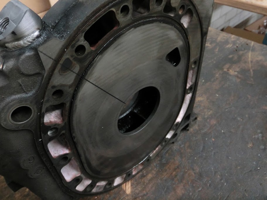
I made sure that the outer surface of the stationairy gear is perfectly inline with the bore by machining it like this:

Fitting tool machined on the lathe, slight pressfit with the stationairy gear.

Stationairy gear pressed on the fitting tool using the tailstock. After this the outer surface is machined according to the hole in the intermediate iron.


Then the main bearings were pressed in the stationairy gear and the iron, stationairy gear, rotor and e-shaft is mocked up so clearance can be checked.
Just like stated in the tech manual like this:
 .
.I use these measurements to rotate the stationairy gear in the intermediate iron. The outer diameter of the stationairy gear is round, and so is the hole in the intermediate iron, so it can be rotated. The measurements show which way to rotate it and how much. In the above picture out of the tech manual you can see four arrows, which are points where to check clearance. By rotating the stationairy gear I found that I can set it up so that the upper and lower left clearances and the upper and lower right ones are equal, but I fail in getting all four ones equal. I ended up having about 0.35mm's of clearance on the left side, and about 0.6mm's on the right side. This meant something was off. First I tried using different rotors, which made no difference. Then I tried using different rotor housings, even unmodified, almost new ones. Also made no difference. Then I tried rotating the stationairy gear exactly 180 degrees, to see if the problem moved with it. which it didn't. After that I removed the stationairy gear from the intermediate iron, got another iron, fitted the stationairy gear in there and checked again. This time I had about 0.45mm's on one side, and 0.5mm's on the other side. At least it's within tolerance now
 . I think the problem might be that when the intermediate iron is produced at the factory not a lot of care is taken where exactly the hole in the intermediate iron is. Normally not a problem, since it's not made to hold a stationairy gear in there.
Anyway, I think using this iron will fix it. Kind of sad that I spend all that work into the other one, and that's now junk. I'm pretty much done modifying the new one though!
...., i would also check your land clearancing also , we do this on high revving motors to reduce the likelyhood of the tips /faces of the rotor clipping the plates at high revs , the reason the rotor the housing shrinks is most likely has been rebuilt or heat cycled a large amount of times , and this causes the alloy to crush up , So definatly mesure your housing widths to see if they are within spec there also ,
Im also currently building a 26b pp and have been racing rotary turbo engines and building them for over 11 years ,
Im also currently building a 26b pp and have been racing rotary turbo engines and building them for over 11 years ,
I totally agree on the land clearancing. I thought checking the land clearance is pretty standard on all engine rebuilds? The factory service manual even tells you to do it! (and then hit the rotor gear with a hammer if there's too little clearance
 ). Mine were already like 0.18 - 0.20mm's, I believe I ended up using 0.24mm's.
http://home.tiscali.nl/millertime/Images/4rotor.jpg
Ok, now that that is said, maybe you can contact Kees Hoebeke in Riland.
He's got one 4-rotor running.
I know he knows stuff...
Here's his monster when the RX-7club visited him last year:
Revealing the RX GARAGE RX8 4 Rotor to the RX7club - YouTube
Grtz Dennis.
Ok, now that that is said, maybe you can contact Kees Hoebeke in Riland.
He's got one 4-rotor running.
I know he knows stuff...
Here's his monster when the RX-7club visited him last year:
Revealing the RX GARAGE RX8 4 Rotor to the RX7club - YouTube
Grtz Dennis.
That picture made me lauch, so true though!That RX-8 is nice isn't it, I haven't seen it in person yet but I've heard some funny stories about it, something about the rear 2 rotors and carburettors actually being inside the car
Junior Member
Joined: Jul 2011
Posts: 8
Likes: 0
From: New Zealand
I see what you mean now , i thought you were referring to the width of the rotor being beyond specs of the housing not the outer faces getting to close ,
A lot of drag racers cnc those faces also as at 10,000rpm and 50psi of boost the faces can tap the housing causing the apex seals to get pinchedand stick , but as you have confirmed it was an off centre issue all of that is irelivant , I have even struck the rotor bearing boar being to small causing bearing tollarance issues from factory ,
I wonder how good there quality controll is as i got some rx8 stat gears for a customers engine last week and the bearing wasnt even line up correctly on either of them , maybe they are employing slave labour to cut costs , ?
Your machining and tech diagrams blow my mind with all the testing you have done , id love your inlet manifold for my 4 im doing for my drift car, variable inlet runner looks awesome ,

Thread Starter
Joined: Oct 2010
Posts: 605
Likes: 13
From: The Netherlands
Probably not much, When the alignment of the 3 main bearings is a little off the e-shaft will bend a little bit. It doesn't require much force to bend it 0.025mm's because the shaft is so long, combustion and weight forces are much much larger.
By the way, the fact that I measured 0.45mm's of clearance on one side and 0.5mm's of clearance on the other side does not mean that the gear position is off by that amount. Even if it's perfectly centered there can still be a clearance variation, that's why the manual says to check it and gives a tolerance.
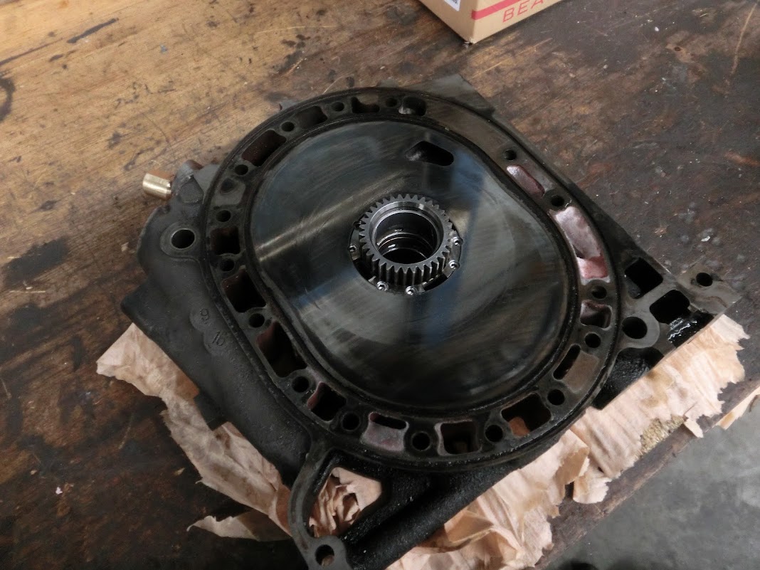
Anyway, I modified the other intermediate iron today, came out good!, The improvements of this setup versus the version I initially made:
- FD S6 stationairy gears with hardened teeth and multi-hole bearings (was FC S4)
- Larger and more (8 instead of 6) oil return slots
- Thicker tube to supply oil to the stat. gear, 14.5mm O.D. (was 12mm)
- More reliable sealing method to seal the oil supply tube, Uses a teflon ring.
- 16 M8 mounting set screws that lock the gears in place, (was 8)
And best of all, the rotor - to rotor housing checks out ok when using this intermediate iron. It kind of sucks that I didn't get it perfectly right the first time but I'm glad I gave it another go.
Here is a picture of the iron, I need to clean it and fill the side ports, but the hard part is done
That bronze looking thing on the top left is the oil supply connection.
By the way, the fact that I measured 0.45mm's of clearance on one side and 0.5mm's of clearance on the other side does not mean that the gear position is off by that amount. Even if it's perfectly centered there can still be a clearance variation, that's why the manual says to check it and gives a tolerance.
Anyway, I modified the other intermediate iron today, came out good!
, The improvements of this setup versus the version I initially made:- FD S6 stationairy gears with hardened teeth and multi-hole bearings (was FC S4)
- Larger and more (8 instead of 6) oil return slots
- Thicker tube to supply oil to the stat. gear, 14.5mm O.D. (was 12mm)
- More reliable sealing method to seal the oil supply tube, Uses a teflon ring.
- 16 M8 mounting set screws that lock the gears in place, (was 8)
And best of all, the rotor - to rotor housing checks out ok when using this intermediate iron. It kind of sucks that I didn't get it perfectly right the first time but I'm glad I gave it another go.
Here is a picture of the iron, I need to clean it and fill the side ports, but the hard part is done
That bronze looking thing on the top left is the oil supply connection.
Last edited by John Huijben; Feb 17, 2013 at 04:57 PM.

normally it doesn't have to be but Mazda has never been all that great about the bore angles.
the 20B engines i tore down had the most wear on rotor #2 against the thick iron, you can guess why.
the 20B engines i tore down had the most wear on rotor #2 against the thick iron, you can guess why.

Thread Starter
Joined: Oct 2010
Posts: 605
Likes: 13
From: The Netherlands
Here is a 3000psi map sensor that hooks up to any programmable ecu, go nuts!


I did some more reading about that by the way, mazda factory manual says a clearance between 0.4 - 0.7mm is needed, mazdaspeed says 0.45mm - 0.75mm, and the 'how to mod your rx-7' book says 0.26mm minimum if the engine stays under 8000rpm, 0.38mm min. if the engine goes over. They also say that if the rotor to housing clearance is too little the critical part of the rotor flank can be machined away without any issue except that it lowers compression, and it obviously affects rotor weight and thus balance.
https://lh3.googleusercontent.com/-j...2/CIMG3086.JPG
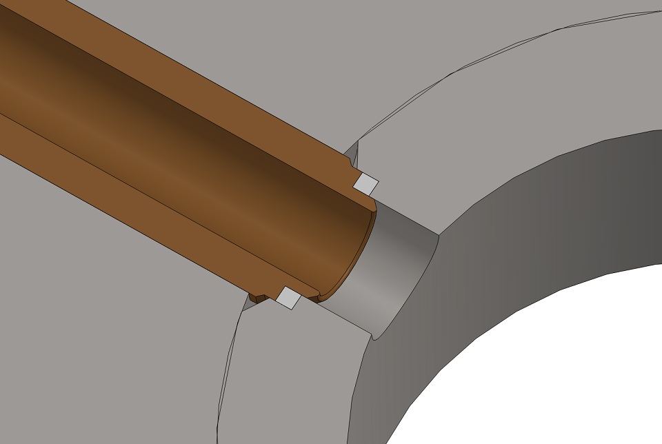
The tube that connects to it is a bronze tube that fits partly inside the teflon ring, this prevents it from being 'squished' out when the tube is tightened. The tube itself is screwed into the intermediate iron. Here are a few cad pictures:

gotta keep in mind these engines aren't reamed to match a particular block like a V8 engine when it is line bored.
these parts are all built with particular tolerance allowances which i would have to guess aren't very stringent. the dowelling method doesn't always align everything in the block exact two times in a row. each engine is picked out of a pile of mass produced parts and assembled.
it still works fine but if you're a stickler for matching tolerances always you will be disappointed eventually, no matter how much you try. it's just another inherent issue with the engine design. for high revving applications looser is better than tighter when rotor clearancing is concerned. on drag racing engines i cut the tops off the rotors and clearance each of the six side edge tips.
Last edited by RotaryEvolution; Feb 19, 2013 at 06:30 PM.
Wasted spark plug
Joined: May 2012
Posts: 64
Likes: 0
From: Enschede, The Netherlands
Why Teflon�?
Works great when used in steady temperature conditions but it will loose shape when going through heat/cold cycles and sure it will start to leak, especially under high oil pressure.
Why not a (heat treated) copper ring? Or alu for that matter?
Grtz Dennis.
Works great when used in steady temperature conditions but it will loose shape when going through heat/cold cycles and sure it will start to leak, especially under high oil pressure.
Why not a (heat treated) copper ring? Or alu for that matter?
Grtz Dennis.