When you click on links to various merchants on this site and make a purchase, this can result in this site earning a commission. Affiliate programs and affiliations include, but are not limited to, the eBay Partner Network.
For the longest time I've been saying how I should make a build thread, even if only so that I have a place to share progress on random things and keep a project log of sorts. Unfortunately starting this thread now means that I've missed the most active part of this car's story (so far) as that has been the past couple years and these days I'm running shorter on time. Given that there's already been a lot done on the car I figured I'd give a quick backstory and then list the current changes/fixes.
Beginning with a little history here, this car had been sitting in a field for 16 years at the time of my purchase. This is out here in Oregon, so rain and consistently damp weather is frequent, although thankfully we don't salt our road. Having sat out there for so long the weather seals had been long cracked and water began to make its way into the interior. The sunroof had some considerable rust, although the majority could only be seen from the inside. There's also a couple rust holes in the body (in addition to the sunroof), which to this day are still covered with routinely replaced with duct-tape. Going a little further back this car had supposedly been in the midwest as well as California, although I don't have any records to prove those claims either way. It had been taken off the road because it could no longer pass smog, however the previous owner said they had tried to start them up every once in a while. Now then I did say "them" because there were two. This is actually my second RX-7 by a couple months, the first being a white 1982 S model. I had originally planned to fix that one up, but after tearing into it I eventually realized that it had far too much rust and was also in a front end collision that lead to a bend frame rail.
Now I don't want this to get too long here, so I'll skip over some of the long and boring. Both cars were originally going to be headed to "charity" and would have raked in $100 a piece to the old owner as he needed them gone to sell his property. Fortunately for me all this meant was getting them out of there before charity could and for a whopping $200 I was the owner of two supposedly running first gens. The white car ended up getting fully stripped for parts, and was eventually scrapped, while the blue is what I am driving today. Getting the blue car running was a heck of a time. To summarize, the engine was seized, it had the acv port plugged so it couldn't pass smog, and it smoked out the neighborhood with regularity. Finally got it running well enough that we could drive it around, only to have the brakes fail catastrophically. Thankfully the worst of it occurred overnight, but what happened is the master cylinder main seal completely failed and dumped all the fluid on the ground. The pedal had been sinking for a while so I'm glad this is how and where it finally went kaput. Passing smog took a few months, but eventually I managed to pass by 1ppm on hydrocarbons. Yes, 1ppm.
Some time went by with me fixing lots of little things which I'll list below, but the most notable is the new engine. I had actually gotten the engine from the white car running on ether before we tore it down, so it was known to be somewhat decent. A little over a year ago I took advantage of some free time and opened it up, cleaned everything really well, and ported it. It was my first rotary engine rebuild ever and suffice to say it's still providing me with load of fun to this day. I had a couple issues with it - like a crushed thrust bearing that took nearly a year to diagnose and fix - but overall I couldn't be happier with how it's worked out.
Now to list what I've done (or what I can remember that I've done, there's been a lot), so here we go:
The Boring:
- new wheel bearings and seals all around
- new u-joints
- replaced differential with new bearings
- new weather seals (doors and windows)
- repairing the rusted tail light wiring and connectors
- cleaning up and re-sealing the tail lights
- new front brakes
- new brake master cylinder
- new wheel cylinders
- new clutch master and slave
- new clutch hard line
- replaced windshield washer pump and reservoir
- removed cold start assist pump and reservoir
- removed hot start assist motor
- swapped to FB charcoal canister setup
- serviced and rebuilt the windshield wiper mechanism
- swapped headlights
- replacement headlight motor bushings
- replaced lower grill/valance
- rain water drain line cleaning
- sunroof rust repair
- cowl rust repair
- serviced window regulators
- fixed horn
- various wiring shenanigans
- on my fourth used transmission
- new shifter bushing
- all new fuel lines
- recoated fuel tank
- undercoat touch-ups
- new engine and oil cooler mounts
- competition transmission mount
Go Fast Parts:
- rebuilt S2 12A with an enlarged '74 spec port job
. - S3 oil pump
- custom RB exhaust
. - RB 83-85 Power Pulse Muffler
. - RB Universal 2.5" Presilencer
. - RB thick wall piping
. - RB collected header
. - custom laser cut flanges
- hogged Nikki
. - trimmed and polished boosters
. - 24mm primaries, 30mm secondaries
. - retimed mechanical secondaries with custom linkages
. - SA throttle shafts for smaller butterfly screws
. - diy zinc plating on almost all steel parts
. - choke delete with fast idle remaining
. - complete smog delete
. - internal fuel screens removed
- modded intake
. - shutter valve delete
. - channel cut in rear runners
. - extra ports filled
. - runner profile smoothed out (weird curves filled/trimmed)
. - casting imperfections removed
. - acv delete
- RB air cleaner housing and K&N E-2700 element
- DLIDFIS
. - DR100 ignitors
. - shielded pick-up cable
. - aluminum mounting plate
. - relay powered from battery
. - MSD High Vibration Blaster 2 Coils
. - Taylor Spiro-Pro 8mm plug wires
. - BUR7EQ's in leading, BR8EQ14's in trailing
. - trailing running through leading spots on cap
. - rebuilt and polished dizzy
- Carter P4070 fuel pump
. - relay powered direct from battery
- inline Edelbrock pre-filter
- stainless hydraulic flex lines (brakes and clutch)
- eBay aluminum radiator
- stainless fmoc lines
- AEM UEGO wideband and gauge
- Energy Suspension poly bushings (except rear arms and watts link)
Extras:
- LED cluster lights
- Tomei duracon shift ****
- fast idle toggle switch
- relayed headlights (black dragon kit)
- Banzai dual belt alternator pulley
- Banzai adjustable alternator bracket
- FD alt swap
- 2x Kicker 4" (front), 2x Kicker 6.5" (rear)
- Pioneer head unit (soon to be replaced, it's possessed)
- Bazooka 6" tube subwoofer concealed under rear "bin" area (no bin's because SA)
- disabled emissions control unit and depinned engine harness
- repainted radiator supports and headlight motor brackets
- no dome light because it tried to catch on fire (haven't dealt with it since)
- rebuilt/serviced sunroof latch mechanism
- Grant steering wheel with janky (but functional) horn repair
That's all I can think of for now. I'm sure I've missed a fair amount, and I've only really included the permanent changes and not any work that occurred as a part of doing something else. Since that was a decently long list I'll leave the backstory and stuff here for now. I'll try to grab some pictures at some point as well.
Near futures plans are installing my BC coilovers (they're still here in their box, just haven't gotten to it) as well as tracking down my exhaust ticking noise. Hopeful short term plans include installing an e-fan (my second clutch fan is going out), installing a light flywheel and new clutch, get the differential spider gears shimmed, driveshaft balancing, resurfacing my header, perhaps some fog lights, and eventually an oil pressure and water temp gauge. Further off plans are some 15" wheels and better tires, a blow-thru turbo setup, a new paint job, and maybe some more suspension mods. That should wrap it up for now. A happy rotoring to all!
Last edited by Benjamin4456; 10-22-20 at 11:02 PM.
Reason: forum ate my indents
Admittedly I don't have that many good pictures of the whole car, but here's a couple decent ones I've dug up.
It's definitely not a looker, but also not too bad from a distance. The hood is showing the worst peeling and the rest of the car is just oxidized, particularly on upward facing surfaces. I'm holding off on paint until I can do it right - strip the whole car, do rust repair, maybe tank it, and then respray the whole thing. There's a couple holes in the body; one in the hood (I have a spare hood I'll use because this one is far gone, only can get three bolts in it) and one in both the wiper cowl and by the hatch. I maintain duct-tape over the latter two to keep water out of the car.
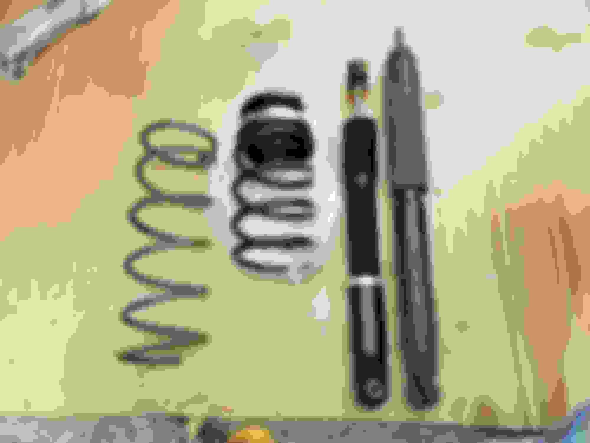
On a different subject, I was finally able to install my BC Racing coilovers that I've had sitting around for months. The install took longer than expected, although the results are wonderful. But first, some pictures.
I assume this kit is more designed around the FB, as at max ride height my front was lower (SA's have slightly longer strut assy's). Due to that I had to lower the rear about a half inch (not seen in the photos) and that got things sitting pretty level. Otherwise it's adjusted as high as it will go, and even then it's still about 2" lower than before. Out of the box I adjusted dampening to (from full hard) 12 front and 10 rear. Suffice to say that was too stiff for a daily driven vehicle. After a couple hours of fiddling I've ended up at 20 front and 16 rear which seems to be a pretty good compromise between comfort and performance. Driving around the difference between these and my, presumably original, stock suspension is huge. Shifting is tighter and I no longer get thrown forward with every gear change. Corners are impressive, I feel like I'm in a go kart with the reduced body roll and how much better it sticks to the ground. I would actually argue that there is less suspension noise as my old parts were shot, and the ride is a bit stiff over badly done patches and large bumps, but on decent roads it's still very comfortable. Unfortunately it's been too wet lately to really lean into any corners, but even so I'm impressed with what I've encountered so far. The tail end does get loose a lot easier now and I've pulled the tires (cheap all seasons) loose in second a couple times on drier roads. That said it's really easy to control and goes dead straight when spinning.
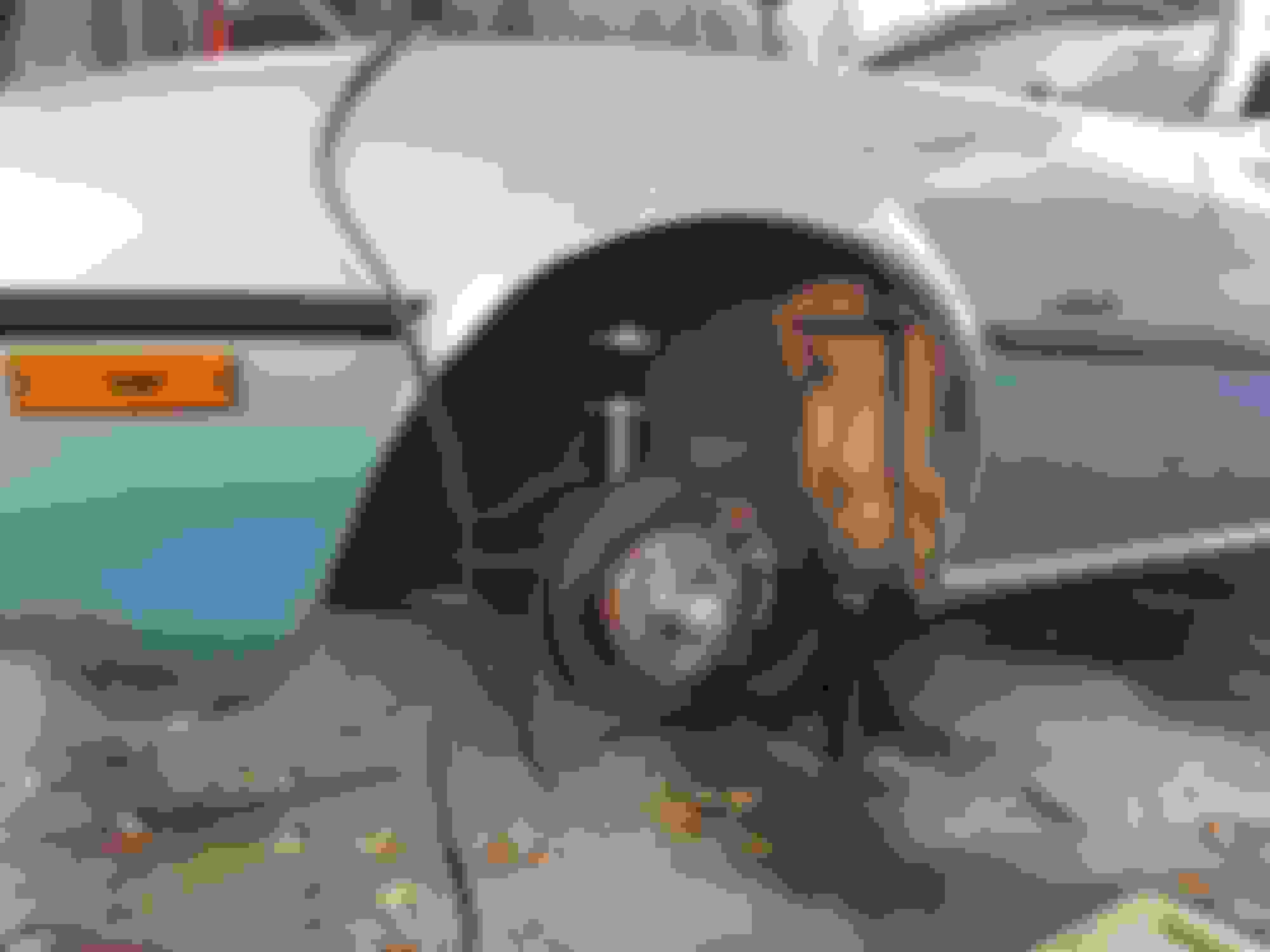
Overall installation was easy, just time consuming when doing it under a canopy in the rain. The only part I had difficulty with was removing the old springs in the rear, mostly because I didn't want to unbolt any of the trailing arms. It ended up working out, but I did have to go through a few different coil compressor designs until I found one that would fit (my normal single action one is far too large). I raised the exhaust up at the same time, as before the limiting factor was how far the suspension could droop when unloaded and hence setting the ceiling at where the driveshaft would collide with my large resonator. Now that that's no longer an issue with the shorter suspension travel, the body of the car is my new limit on the exhaust. Fortunately I have managed to clear every speed bump I've encountered thus far, although the margin must be pretty slim. I did scrape on a steep driveway though.
Once we get a little dry spell I'll go ahead and re-tighten the front hubs now that they've settled in. I also need to raise the driver's side rear just a hair.
Oh, and just a clarification about ride height adjustment in the rear, as I've seen some first gen BC threads with people being confused about it. The way you do it is first adjust the ride-height by using the included adjustable spring-spacer. After that use the threaded shock bodies to adjust the preload on the spring. According to BC this should be no more than 5mm, so I aimed for about 3mm. Essentially you're just trying to get it so that the spring has no room to move around, that's it. The ride-height and preload are still independent on the rear, like the front, but in order to adjust ride-height you must also adjust the preload in order to keep it where you want it. It's a little cumbersome, but thankfully it's not something you'd mess with often if ever again.
So yeah, just a little update with the new suspension installed. I also found another large wasp nest while pulling out the old parts - it was under one of the strut mounts. For context this car spent it's first year attacking me with recurrent wasps. I've probably taken out at least twelve good sized nests plus a bunch of little ones.
Awesome thread, good read. So just 12 nests? Not 13 Bees? I'll show myself out.
Glad you're enjoying the thread. Next up on the list is an e-fan. I've got it sitting right here next to me, a Flex-a-lite 105390. Pulls 3,000 cfm at just under 20amps if I recall correctly. It's actually been here for a few weeks and I just haven't had the time or the weather to get it in, although hopefully within the next month or so I'll get a chance. At the same time I'll be redoing my disaster of a power distribution block with some proper ATC fuse blocks - currently it's just the factory fusible link block with seven wires or so coming off that poor little threaded terminal. I may also replace the factory links if I can find a slow-blow fuse that fits in an ACT holder. I know they make some that will fit in the stock block, although I was hoping to replace it as well to help clean things up.
Reasoning for the e-fan is I've already gone through a couple clutch fans that, while they work, do not work correctly (they either engage too often, or stay engaged too long/don't reliably disengage fully). I'm aware of the e-fan debate, although my logic is that for the about the price of a new, guaranteed to work clutch fan I can take a shot at an e-fan and maybe free up a couple horses. I'm also nearly at my limit for NA power gains at this point (without decreasing streetablity) so anything helps. Additionally I'm hoping it will slightly aid in cold start warm up times since it won't spin until I reach operating temp. Oh, and of course I have a controller for it as well, can't forget that.
I'd like to make a sort of shroud for it, although I'm not really sure where I'd find the material. Just hypothesizing, but I feel like the most simple solution would be a strip of flashing around the perimeter of the fan with a notch for the lower tank so that it can seal everywhere else. Since I have an fmoc under my rad I'll be mounting the fan so that it covers both, which of course means there will be a slight gap due to it needing to cross the bottom tank. Anyway, we'll cross that bridge when I get there. I'm sure I can make it work, but to know how is going to require me to actually get the parts in the car and start fiddling.
Last edited by Benjamin4456; 11-18-20 at 01:45 PM.
With the holidays I've had some free time to get a few things done on the car. This post will cover most of what my recent "What did you do..." post did, but a bit more detail, or at least that's the idea.
First things first I got my electric fan installed. It's a Flex-a-lite 238 (16" 3,000 CFM lo-boy puller, no shroud) that I picked up a few months ago but hadn't had the time to install until now. I budgeted two days for the install (given that I don't have an enclosed work area, it's Oregon (cool and damp), and it gets dark at 4:30 right now. Ended up taking two and half days, but I'll call that a win. The fan controller is a single speed Derale 16759 which can switch up to 25A continuous. This fan draws 18.5A so we're clear there. The fan mounting brackets are some Spal 30130011 units, which are cut to length and conveniently fit the Flex-a-lite perfectly. The fan clears the water pump fine, even with the thicker aluminum radiator, and the wiring is tidily routed under the core supports. I was able to stick the controller by the headlight/headlight motor fairly neatly, although it can't be adjusted without pulling the battery out a little. Even so, it's a set and forget type of affair so that's not such a bad deal. Speaking of setting, the "supposed" adjustment range for this controller is 150-240F, and given that I had set the potentiometer at about where I thought it should be - I was way off. My unit seems to have a much lower adjustment range, which works better for this application, but came at a surprise nonetheless. Within a few minutes of idling in ~40F ambient air the fan could drop the block temp by 25F (that was before I had it adjusted right). So far it hasn't turned on once while driving (now that it's adjusted properly) and the only time I've noticed it kick on so far was when sitting in a long line for gas earlier today. Of course it's pretty cool out right now, but even so I'm pleased. Once summer rolls around it will actually get put to the test; hopefully it passes.
I also took this opportunity to do some electrical tidying. Slowly more circuits have been added to this car and at the point of this project taking place there were five circuits all being fed from the one ring terminal on the fusible link block. Suffice to say it wasn't pretty or a very good solution, so I went ahead and picked up some small fuse blocks (made by Dorman I believe...?) to remedy the problem. I chose them because they were nice and simple. So much of what I saw for other options were large, clunky, and looked sorta cheesy/flimsy with their clear plastic doors and whatnot. Anyway, these are not the most amazing in terms of quality or craftsmanship either, but I liked the simplicity and that they blend in well. Now I have my fuel pump, alternator sense wire, subwoofer, headlights, engine fan, and ignition system all properly fused and with nice fresh wires feeding right off the battery, plus two more spots for future additions. Additionally, I replaced the main electrical battery feed wire with a new 8ga. line as the old one was the wrong kind of wire (CCA and really stiff) and it's terminals were done poorly.
Headlights were another thing I was able to update with my downtime. I've gone ahead and installed some Hella H4 conversion housings (PN 002395301 for DOT approved, LHD units) that accept replaceable halogen blubs. Interestingly they are technically a 9003 housing (US spec) but 9003 and H4's are essentially interchangeable. For US applications 9003 is of course more common. Overall I quite like them. My old Sylvania XtraVision blubs were fairly bright, but they made two distinctive bright spots with a rather uneven spread and poor extension far to the sides. These Hella's have a really crisp upper cutoff (which is nice for the oncoming traffic) and a very consistent beam pattern/spread. I can see further to the sides than with the old blubs which was one thing that really annoyed me before. Certainly quite happy with the change. At some point here I'll get some LED's to further improve visibility and reduce electrical draw (my wiper motor will thank me).
A new clutch was also on the list of to-do, the old one having gotten a little burned up from the thrust bearing disaster. In preparation for boost I've gone ahead and opted for the RB street/strip disk and a stock Exedy pressure plate. Reason for not going a different route is that I'm stuck with my 215mm flywheel for the time being and there aren't many pressure plate options for it. I'd like to eventually get a light flywheel and at the same time switch to the 225mm setup, but the cost was a bit prohibitive for the time being. Part of the logic was the cost of a light flywheel setup (about $800 plus shipping the way I priced it) wouldn't offer nearly the value of a blow-thru setup for the money, while also making daily driving a little bit harder. So I've gone the way I mentioned above and honestly it seems pretty tame. Now, I've only got two days on the thing so it's really early to be making any sort of claims, but it wasn't nearly as touchy as I expected. Sure it's a little grabbier than the stock disk, but it's completely manageable and most people probably wouldn't notice much of a difference. It does chatter some when cold (we're talking nearly freezing here), but that goes away once things have some heat in them. Of course it's not even close to broken in, so we'll see if that behavior changes or not.
While the transmission was out I also replaced the output shaft bushing as I had though it was responsible for some of the driveline vibrations I'd been experiencing. I replaced it with the Atkins unit and it appears well made, although it doesn't have the alignment tang which makes me wonder if it may spin over time and potentially block the oil feed. So far it's fine however, although it didn't improve my driveline vibrations by much. Pretty sure my driveshaft is a hair out of balance, but it does have new, tight u-joints. The issues are two fold. First, sometimes when shifting, a vibration appears (most commonly in fourth gear). Sometime I can disengage the clutch, blip the throttle, and re-engage the clutch and it will go away (sometimes after a few tries). It almost seems like the clutch were to be engaging slightly off center, but that seems unlikely given it has been a persistent issue with multiple used transmissions, clutches, and pilot bearings. The only parts that have been consistent are the tail housing (and hence output shaft bushing) and the driveshaft/rear end. The other issue I run into is most commonly at highspeed where if I let off the throttle slightly (coasting, not engine braking) lots of vibrations begin. My diff's spider gears have some slop, although it isn't horrendous. Only other thing I can think of is the driveshaft. Perhaps the slip yoke has worn too much? Not sure. Fairly certain it's a junk yard shaft. Anyway, as soon as load returns to the driveline the vibration subsides. Worst speed it happens at is right about 70mph.
Anywho, those are the major things, but here's a few minor things to wrap up this post. Today I did an oil change and at the same time added some grey rtv to each of the three bolts that hold in the oil level sensor. I had replaced the o-ring for it during my rebuild, but hadn't thought about the bolts leaking a little bit. Turns out they do (I mean, it's barely any, there's hardly any oil on the pan), so I went ahead and sealed them up. Used up the rest of my 10W40 so next time will be 20W50 again for summer, and then I'll probably stay 20W50 from there on out. I also took care of my squeaking clutch pedal, which was a simple fix. My steering wheel was also squawking so I pulled it and had a look. I had to do some repairs to the horn contact ring a while back, and unfortunately it looks like the adapter (it's a grant wheel) is on it's way out as the copper plating is starting to wear through. I've gone ahead and ordered a new one and just thrown some grease on it for the time being to keep it quiet (I have had to regularly grease this wheel to keep it from squeaking). All of the support bolts were also loose so I added some loctite and snugged them down. Steering feels a lot better now (doesn't click/pop with high force as it was loose before) and no squeaking makes driving much more pleasant. I've also stuck some foam under the instrument cluster trim to keep it from rattling and that's been a nice improvement so far as well.
So yeah, there you have it. Another update done. Hopes are to go blow-thru later this summer, although I'm not sure yet if the budget will allow it. For now happy New Year! Hopefully 2021 is a lot better than 2020 has been.
Got home from a drive this morning and popped the hood to check the oil level. The level was fine but I noticed a dark splotch on my undertray below the oil cooler fittings. Turns out I've got some degree of a leak, which is sort of sad as this car has been 100% leak free for a while now. Fortunately it's not the cooler itself and appears to be coming from the lower line's fitting. Unfortunately they aren't loose so it looks like I have some new lines in my future. The set currently installed isn't OEM and I assume was made by the PO. They're nice stainless lines but they are a hair too long (and really stiff) and so they put the oil cooler fittings under a little stress 24/7, perhaps that's what led to the leak. For now it's just on my watch list as it doesn't leak while running, even at 3k rpm, and doesn't really seem to leak right after shutting it off either. Only thing that concerns me is that it could suddenly blow (unlikely since the leak appears to be coming from the threaded portion) but I have an oil pressure gauge that is ready to be installed whenever I have the time.
Something brief but slightly amusing - about a month ago I was driving around when suddenly something fell on my foot. When I got home I dug around in the footwell to find one of the finger nuts from my wideband. What's odd is that there are so many wires and everything back there that I can't imagine how it could have fallen on my foot and not just gotten stuck behind the center console where I never would have noticed it missing. Anyway, it did and so today I finally got it reinstalled and my center console now has one less rattle.
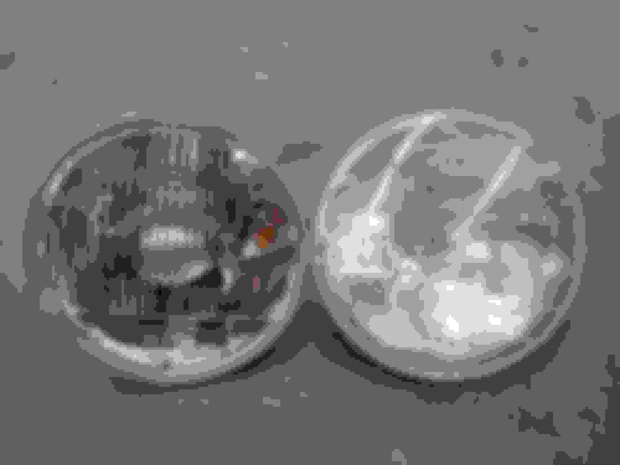
Last for now is progress on the turbo setup. I already mentioned this in the dedicated thread but my manifold finally arrived today. Took about a week and a half to get here (Oregon) from the east coast of Canada, in the process disappearing from the USPS tracking system as things seem to do these days. It's an original JDM 12AT manifold that has been modified with a spacer to (in theory) clear the Nikki manifold. I won't know for certain until work begins in... a while.... but for now I'll just hope that it's all good. The spacer also has an external waste gate port which is nice for the added flexibility. It's a T3 flange although it also came with a T4 adapter. So anyway, yeah, I like it. Upon first seeing the thing it looked absurdly small - and it still does - but I guess I had just forgotten how small the engine really is. Here's a few photos.
I also thought it was somewhat amusing that the package it came in was roughly rotor shaped:
It's been a little while since I've touched this thread. By now the turbo is installed and working (for the most part) and we're sitting on some Konig Rewinds wrapped in 205/50R15 Hankook Ventus Concept2 V2's. As of now I'm planning on building a new engine for the car next summer, although the current engine still needs to last until then so I can't do anything bonkers to it just yet (and I've already cracked one iron, yippee - that rebuild has come and gone). Turbo thread is here for anyone who missed it: Blow-thru Nikki Setup.
Going forward there's a number of things I have on my radar. One of which, and this might be a surprise to some, is going EFI. But not just EFI with a throttle body injector setup or swapping in a 13B, nope, that would be too logical. I've been toying with the idea for a while of trying my hand at casting. Some friends and I have quite the stock pile of scrap aluminum (heads, cases, and whatnot) and we've wanted to get a small foundry up and going again. I'm thinking of designing a 12A LIM that matches up to an S4 UIM flange. Lost PLA would let me cast the shape since I can then 3D print the plugs to my design and then use them to make molds. This of course assumes that I can melt that much metal at one time. Might be a stretch, we'll see. This is project for next summer or beyond, although if anyone here has experience with DIY casting please do share. I'm all ears.
In the more near future I have some other things to tinker with though, the first being 3D printed Nikki venturis. For a few months now I've had some carbon fiber nylon calibration cubes (20mm cubes used for printer axis calibration) sitting in vats of gasoline. So far there has been no appreciable change to the dimensions, color, strength, etc. of the cubes. While originally a test to ensure my carb hats wouldn't dissolve, this has now become a confirmation that 3D printed venturis of this material will not degrade. In fact, I have five carbon fiber nylon venturis sitting next to me as I type this. Plan is to install them within the week in replacement of my hand-cut metal venturis. Hopefully this will not only be an opportunity for proving these viable, but also an improvement over my set of metal ones as - being my first set ever - they had a couple places where I overcooked the edge with the die grinder. I'm also stepping back down from the 30mm secondaries that I was running to stock sized 28mm venturis but with straight tapers to provide a stronger vacuum signal in order to reduce the secondary transition glitch. If these prove reliable they will likely be up available for purchase soon.
On the topic of 3D printed parts, I've also finished the prototype SA center console plate. Realistically the design is in its final form, however I have yet to print it in ASA which will be the final material. So far I'm very happy with the result, which, while not terribly unique looking, is a direct fit replacement console plate with the addition of three gauge mounting holes and provisions for a single DIN radio. I hope to have it available on eBay by the end of the month for anyone who may wish to install a radio or gauges but doesn't want to cut up their original console plate.
Other things on the to-do list are:
- fix the heater box temperature adjustment cable
- wire up the light for the boost gauge
- wire the low-oil (2-stroke) warning light
- get an oil pressure gauge
- investigate the popping sound under boost
Circling back to the EFI idea for a moment. I figure four injectors will suffice (all on the manifold since the 12A didn't have center iron injector provisions), although I haven't gotten too far there yet. The whole world of EFI is new to me. It's certainly very interesting and whatnot, but I've got a lot to learn still. Seems like a MS3X would do the trick without breaking the bank, although I haven't done much other looking, it's just the first thing that came to mind. It also looks like an FC CAS system would work for getting a crank signal and still using a mostly stock 12A front cover, although as is the theme here, more research is needed. Conveniently I already have a larger fuel return line run, so that's something I wouldn't need to touch, although a bigger pump and higher pressure regulator would still be on the list. The primary reason for even considering EFI is that for a daily driven vehicle, there are too many benefits to EFI to deny it's superiority. I love carbs, but sometimes you don't want to wait five minutes before moving an inch, or want better gas mileage, or more precise control over the fueling so your turbo doesn't send bits of your engine into low earth orbit, etc. while still driving a 40 year old sports car. I also just want to learn how to tune modern day stuff since that's where it's all going anyway.
Anyway, if anyone has thoughts on anything here please to share, and feel free to spitball ideas. I want to figure out how to make this stuff work one way or another.
Oh yeah, and that DIY headunit project is still a thing - somewhere in a box in a closet... One day I'll dig it back out again; for now there's too much else to deal with.
Here's a couple photos to close things out: CF-Nylon venturi test fit on junk carb body
Driveshaft shroud fell off and gave me a heck of a scare. Tacked it back on and we're good to go again.
Thanks for the update, I enjoy your long prose style and how you lay out what you're thinking. One way to check if you've got enough material is to take a bath with Archimedes, i.e. put your scrap in a bucket of water and measure the displacement. Maybe the 3D printer app can give you a calculated volume to target?
You made me go google lost PLA casting methods! TIL, there are special filaments optimized for melting out of the plaster, and special plasters that can handle greater expansion of PLA compared to wax on melt out.
It's always nice to hear that some people enjoy reading this stuff. As for the water displacement method, yes, I hadn't thought of it before but I will certainly do that to confirm I have enough metal. In the prior post I had actually been referring to whether or not I will be able to maintain such a large amount of metal in a molten state - no dinky 5 gallon bucket foundry will work, that's for sure. I'll figure something out, even if it means it will take an eternity to reach the proper temp, I'll make it work somehow.
Lost PLA is something I too had to google recently as I hadn't really toyed with the concept until now. I also ran across the specialize filaments and plasters and it looks to be a fairly established method of producing molds, although I have yet to encounter an example nearly as large as what I'm planning on here. Typically it appears to be used for small trinkets and some miniature sculptures, not sure about something as large as an intake manifold.
And yeah, it surely will be interesting - hopefully even cool! I'll start chipping away at the manifold design within a month or so and go from there. It'd be awesome if the system can be ready to go this coming summer, although I don't yet know if I'll have the time or budget so soon with preexisting projects already on the books.
So I've been doing some thinking. A lot of thinking, and it seems there may be an ECU, injectors, wiring, and some other goodies presently headed in my direction....
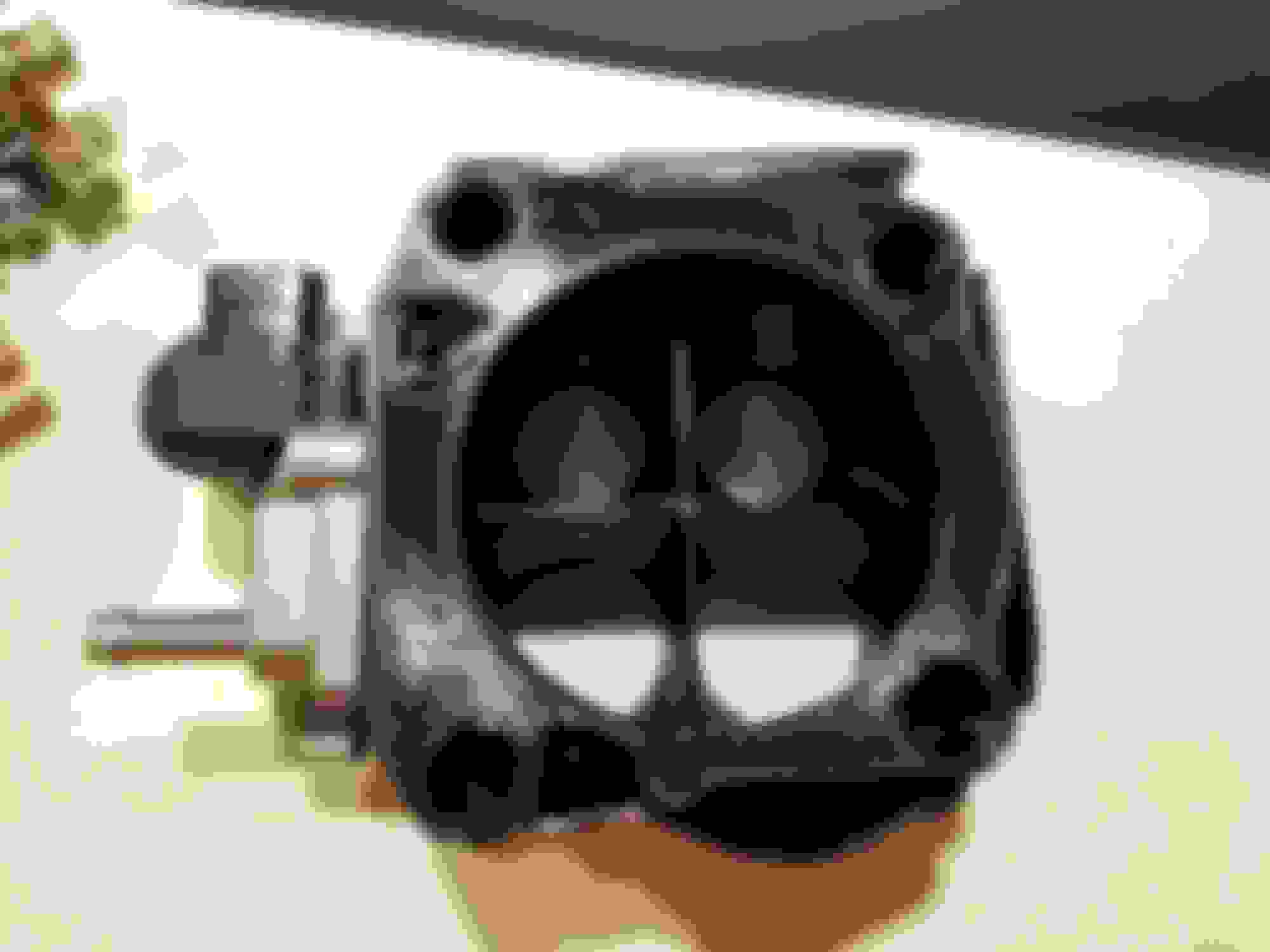
After some recent issues with my carb and the turbo setup being displeased with the weather cooling down, I've decided it's finally time to ditch the carb and go modern. While I would love to cast a custom intake manifold and all that jazz, realistically I do not have the time or space to deal with that in the short term so.... custom TBI setup? I've been working on the best way to convert to EFI in a budget friendly manner and the Holley Snipers have always seemed like an interesting direction. Alas that's not where I'm going, primarily because I don't want to be locked to a box with an ECU inside of it - I want flexibility.
So that gave me two main options. Either A, weld some injector bungs into a Nikki manifold, or B, figure out some TBI setup. Since there isn't a great way to orient injector bungs in the Nikki manifold, especially with the turbo right next to it, I'm going down the custom TBI route. And I do mean custom. Pair a Honda 70mm throttle body with some EV14 fuel injectors, a Honda IACV, GM IAT, some wiring, a Speeduino, a custom Hall Effect CAS, and a 3D printed baseplate tying it all together with a few other bits and bobs and we're going to have something, hopefully. This has come together over only the last week or thereabouts, so it's all rather fresh, but I'm quite confident that this is going to work and work well. At this time I'm waiting on parts to arrive so that I can start measuring things and designing my base/adapted plate. I figure this project will slowly progress over the next few months, with my goal being to have the car ready to start tuning by the holiday season. We'll see how realistic that turns out to be.
Getting a little more in-depth on the setup, the basic premise is building a Sniper with an external ECU and the position of everything swapped around a little. I'm not actually using a Sniper for reference at all, it's just the concept that is similar. I mean, realistically any 80s-90s TBI setup will be somewhat similar, although this will be designed for common injectors and easily attainable other components and sensors. The throttle body itself is a rep Skunk2 70mm B/K/H/whatever series body. Seems like people have had pretty good luck with the rep ones and if something does have an issue I can purchase a legit one and it'll bolt right up (keep in mind this is a budget setup for the time being). Conveniently it includes the TPS and MAP sensors which saves me some hassle there. While 70mm might seem a little small for our applications, it is still larger than the total area on a Nikki T-Body, so it's certainly not a step backwards. This is also a "temporary" setup until I can afford the time to cast a custom intake, at which time the majority of parts will transfer over easily.
The adapter plate as I'm calling it will take the Nikki manifold and adapt it to the Honda throttle body. It will also provide a mounting spot for the IACV and OMP nozzles (yes I'm still keeping the OMP). I'll be running four 1000cc Bosch EV14 injectors set up as a front and rear rotor rail. Heat-set inserts will be used to attach various parts to the adapter, and press-in injector bungs will be used to seat and seal the injectors. I'm still working out the best way to install OMP oil jets, but I have a general idea so far. Once I have the throttle body in hand I'll be able to get a better grasp on what I'm dealing with.
For the time being we are sticking with the distributor, but this is only temporary. The first goal is getting fuel working, then we can add ignition. In order to futureproof I'll be using a Hall Effect CAS setup. At first I toyed with the idea of modifying an FC CAS to work, but after seeing the price of a used one and that using it would mean ditching the dizzy immediately, I figured Hall Effect was the better option. While looking around for the best way to do with I came across the Full Function Engineering setup, and although they make some really neat stuff that definitely warrants the price, I just couldn't see the justification in spending $325 on a few laser cut metal bits and a basic sensor. So I designed my own, two and half of which (in order to meet minimums) are presently being cut by SendCutSend. The sensor will be the tab mount model from DIYAutoTune (which looks identical to the FFE one) and I'll be 3D printing the mounting bracket.
The ECU is a speeduino 0.3.x as it appears the 0.4.x is designed with using existing factory harnesses in mind. This is essentially a slightly dumbed down MegaSquirt that you assemble yourself - it even uses the same tuning software. While I've never done anything with ECU tuning before, I'm certainly excited to learn and mess with things. I opted for the model without the on-board MAP sensor, although I think I may revisit that decision in the future in order to add altitude compensation to the ECU. For connectors I've made use of Ballenger Motorsports to source the OEM plugs for the various sensors and whatnot that will be used in this setup, and I was delighted to see that connector kits (not pigtails) are available so that the wires do not need to be spliced. Again, this EFI stuff is all new to me, I'm sure there's folks who have known about Ballenger for ages.
Anywho, the first bits (the ECU) theoretically arrive Thursday so I'm certainly looking forward to that. For the time being, here's a screenshot of the trigger wheel. Please note that this is not at all intended to be a copy or rep of the FFE setup - theirs is just about as bare bones design-wise as you can go, and I'm not one to add much distinguishing flare to something so mechanically simple.
Slowly making some progress with the EFI project. Beginning with what I left off with, the trigger wheel I had laser cut arrived and looks great, here's a photo.
Otherwise I've been primarily working on the throttle body adapter plate, which is coming along nicely. As of now I'm waiting on parts again before I can continue the design, although the bulk is figured out. A couple things have changed my plans slightly - such as the entire assembly needing to be rotated 90 degrees for everything to clear, which unfortunately puts one fuel rail rather near the turbo - although I think it's safe to say that this should work. I printed a prototype to mock up fitment and we're 99% there with the only tweak needed being a slight hole misalignment on the intake manifold side. I've also come up with a better way to route the IACV pathways now that I have the throttle body in hand; turns out the idle air bypass screw has a channel that I was able to access for the IACV so now it's all routed within the adapter and no hoses are needed. A number of connectors, wiring bits, the injectors, the ECU (oh, yeah, I'll talk about that momentarily), and whatnot have also already arrived. Today I discovered that the stock throttle cable will be a little too short so that's on order now as well.
Regarding the ECU, I'm honestly impressed with the whole Speeduino setup. Documentation is much better than I originally would have thought, as is functionality. It's essentially a fully functional Mega/Microsquirt with a few less inputs/outputs for things like traction control and other more complex things. For these cars (if you're staying on the more basic end of the spectrum) they are the perfect solution in my opinion. I picked up the 0.3.x kit (0.3.7 is the current board) which comes as a self assembly thru-hole kit. You need to purchase an Arduino Mega 2560 separately, but they can be had on Amazon for less than 20 bucks. Assembly does take some time, especially if you're like me and get paranoid with making all the resistors, diodes, etc. perfectly centered, but it's a nice thing to do as a break. Alternatively you can purchase a preassembled board for ~20 bucks extra and a couple weeks lead time. Tuning is done with the same software as the Megasquirt family of ECU's (TunerStudio) which is surprisingly full featured and I look forward to working with. Anywho, before this begins to sound anymore like a product placement I just want to say that if you're looking for a budget yet effective ECU do not overlook Speeduino, particularly if you enjoy DIY and figuring things out. I'd say it's probably the best bang for the buck "carburetor replacement" solution if you're not looking for a bunch of extra frills.
To end out this update here's a couple photos of what all I mentioned above.
Neat stuff going on in this thread! I look forward to the next update.
Once I get my SA running on the GSL-SE setup, I intend to replace the GSL-SE ECU with a MegaSquirt or a Speeduino. I'd heard of the Speeduino some time ago, but recently ran across again via SuperFastMatt on YouTube, and it's definitely advanced since the first time I read up on it.
This all also reinforces my desire to buy a 3D printer.
A MegaSquirt would definitely be a good option there. Speeduino is in essence a slightly more sparse featured MS that requires a fair bit more work on the user's end. As I'm making progress here I'm beginning to better see both the appeal and the downsides of the Speeduino. The main upside is that it's quite basic and is great for low feature ECU installs. The downside is then of course that if you want more features, you'll be running out of IO on the Speeduino pretty fast. It also requires a lot more user dedication, as unlike I first thought, documentation for some even slightly off the beaten path features is not great.
I recently spent some time procuring a barometer chip (DigiKey is wonderful) and adding that to my board so that I can have a constant baro reading rather than rely on a single time reading from the MAP on start up. You also have to do your own soldering work in the proto section of the board to add any extra sensor inputs (fuel pressure in my case), and even something as basic as a three wire IACV. Admittedly these changes are not difficult if you're at all comfortable with a soldering iron, but it's certainly not plug and play. Funny enough, SuperFastMatt's channel has been some help to my project as well by bringing up some features I was not yet aware of - the big one being the use of manual injector controls to test the injector deadtime, of which I did not have a spec for. Both the Speeduino and the MegaSquirt ECUs have made huge leaps forward since they were first introduced, and I'd certainly be comfortable running just about anything with them as of now.
And yeah, 3D printers become excessively useful if you're much of a DIY guy. I've used them to create some odd tools (like a fillet gauge which I now use surprisingly frequently), as well as a few jigs and all sorts of other things, in addition to the car parts I make.
Anywho, as far as an update goes I haven't completed all that much recently, although I am presently working out the best way to machine my fuel rails with my limited selection of a drill press and a Dremel . So far the results are trending positive and I should hopefully have a final primary rail done tomorrow night, provided that the incoming windy weather doesn't knock out our power. I bought extra fuel rail extrusion with the expectation of learning from mistakes and it's certainly proving to be a wise choice. That said, it's only taken two attempts to figure everything out and devise the best order to do it all in, so the third attempt should be the final one.
I may still go MegaSquirt myself - I've been in on that project since almost the beginning, having built a MS v1.01 and an MS v2.2, though I've not installed either of them. I still have the v2.2, so I guess I should use it! It was originally destined for my 1970 Cutlass, but that project is slow going.
For your drill press, one of those compound sliding vices would probably help with accuracy in making your fuel rail.
After a full day of chasing sync issues and never actually finding the problem, then cheating my way to success (good ole' ether...) it's running, sort of. The tune is horrendous and I'm sure the low compression engine isn't making my life any easier for tuning idle (that clip is the best it ran and my foot is on the pedal).
This isn't really an update in any means, I just feel some sense of accomplishment after a lot of headaches and figured I'd post the short video clip (linked above). I'll write up a better summary post of what's been happening at some point here. For now, it sort of works. Tomorrow is tune-tackling day.
I had wanted to post a more successful update than this, but it's what I have to work with for now. Perhaps someone will have some ideas as well.
First and foremost, I'm having unending crank sensor sync issues. I've redone the mounting, wiring, replaced the sensor, re-routed the wiring far away from noise sources, etc. Still no dice. What's odd is that it's seemingly random and I just can't figure out why. I've just ordered a cheap logic analyzer to test the sensor and wiring itself, so I'll know a little more once that's arrived later next week. What's odd is that it can be running fine and then just drop sync periodically, or not at all, or continuous enough that it dies. It happens at idle and driving around from 3-4k (haven't gotten higher than that yet). I can't connect it to bumps, vibration, misfires, anything. At the moment my last couple ideas are that it's the trigger wheel (which I designed and had laser cut) or it's the Speeduino (which blew a 15A fuse twice due to my miswiring of the IACV).
The second issue is the fact that it wants to run really rich. Idle no leaner than 11.5 and cruising around the same. My thought is that I shot myself in the foot by using a single barrel throttle body. Reason being is that air is going down all runners "equally" at all times, although fuel is not being injected into the secondaries at low load/idle. Being that my injectors are all located "on" the manifold, I feel as though the primaries are needing to be extra rich in order to compensate for the excessive fuel-free air coming in from the secondaries. That then leads to a rich poorly atomized mixture in the engine and hence it's rich, or at least that's my idea. I'm open to other interpretations. The large throttle body is actually responsive enough from idle speeds though, so I don't think driveability will be an issue aside from somewhat worse mileage than may have been possible.
Presently I'm running 2 squirts per cycle on the two primary injectors at 1.8ms pulsewidths and 1.5% duty cycle (at idle). I'm also thinking that part of the issue is that the injectors are just too large (FIC1000s), especially if I try to run them all at once at idle. Which brings me to the idea of running all the injectors all the time to offset the design flaw of having open secondaries with no fuel. The issue of course would be that I have practically no pulsewidth to divvy up here, unless I go to one squirt per cycle which wouldn't be ideal. Not entirely sure yet, I'm just spitballing here. Testing the rich fueling issues comes after the sync issue is resolved.
The next issue is suddenly going lean for no apparent reason. Watching the logs there is no indication of why it's occurring which led me to the conclusion that the pump is probably picking up air, hence a surge tank setup will be installed pretty soon. When first planning this setup it didn't occur to me that the carby tank simply wasn't designed for EFI consistency which would have been an issue in the long run. However, I had also forgotten that I once suspected my carb fuel system of picking up air (for some unknown reason) and if my EFI system is doing the same thing it would be causing many more issues. Fuel pressure data does not show anything suspect, but even small amounts of air could be causing problems. So, the "two birds with one stone" solution is a surge tank, which will get sorted out once parts arrive.
Circling back to the fuel-free secondary issue, there are a couple other options without fully ditching this idea. The most straightforward would be to pick up a 4 barrel throttle body and use that. They certainly do exist, although are more than I want to spend on an untested idea right now. Using one would also mean buying a new IACV, TPS, and figuring out a MAP sensor, as well as redoing my wiring harness to match. The second option is to redesign the printed adapter plate to somehow have two fuel injectors shared equally between the primary and secondary runners. Space is the limiting constraint here as I have very little additional vertical area to work with, and making this change would likely require the setup to become taller. Going sideways is not as much of an option either as strength beings to become a concern with the heavy t-body hanging off one side. The carb does have channels though (ported SA style) so it may be possible to rework it without too much of a redesign. Realistically I already have a few changes I want to implement on a redesign so it would give me an opportunity for those as well.
Anywho, I suppose that was mostly me thinking out loud. Curious if anyone has any thoughts or ideas regarding the matter(s). I realize I'm complicating my life by doing this odd setup, but I'm far enough in now that I just want to see it work. And it will, eventually...
After talking with some folks on the Speeduino forum, I became no longer particularly convinced that the Speeduino supports full-sequential fuel injection without a cam position signal. Granted I never knew whether or not it did, I had just sort of assume it would work. It seems not, or at least not very well - obviously I had the car running, but the cam signal trace was showing some phantom lines in logs so... I'm not sure about that. Considering I was also getting stuck at half-sync quite often when cranking, I figure this is a reasonable conclusion. However if it ends up that it does support full-sequential without a cam input I'll be sure to update this thread.
My solution was changing to batch/paired injection. Theoretically - well, realistically too - this is not as ideal for precise low speed operation, but it seemed like my only option. As a note, semi-sequential (at least on the Speeduino) is the same as batch/paired except that instead of using two injectors per channel, each injector has it's own channel but the channels are mirrored. The reason why I'm using batch instead of semi-sequential is because, one, it didn't require any rewiring, and two, it allows me to alter the primary vs secondary injector balance, if for some odd reason I ever need to do that (I doubt it).
I had also suspected that with my single barrel throttle body paired with four independent intake runners (each with their own fuel injector), the fueling was far from ideal with just the primary injectors firing. This is because you have air flowing down the secondary runners with no fuel (secondary injectors staged to enable under load), resulting in the primary injectors needing to inject about twice as much fuel in order to compensate for once the two mixtures (lean secondary and rich primary) reach the engine. This probably led to poor atomization in the primaries and then poor mixing in the engine.
So, I enabled the secondary injectors full time to stop this issue. However, the problem with doing only that is that I am running 4x 1000cc fuel injectors. Given that they were already operating at ~1.8ms and 1.5% duty cycle at idle with just the primaries, if I cut that in half to add in the secondary injectors, I would be operating below the injector dead time and all sorts of fun tuning problems would ensue. So to combat this I went from the typical 2 injections per cycle (called squirts by this tuning software) to 1 squirt per cycle. This kept the pulse width the same while also injecting fuel in the secondary intake runners.
And voila! My rich idle and low speed issues are resolved. I'm back to running at a much more reasonable 12.8 - 13.6 (it doesn't vary that much, but it can happily idle anywhere in that range). The sync issue is also less of an issue it seems, although I still have some sync loss off idle that I need to track down. Mind you that I only been messed with these new settings for about an hour this evening, so I'm sure I still have things to iron out that may pop up as time goes on. But for now, we're in a much better spot than before. Especially now that I can stop worrying about needing to redesign the whole TBI setup to balance the injectors in the runners more evenly when only operating with two injectors at low load.
Woohoo! I'm excited again. Now to just solve that darn sync issue...
Now I'm in the process of installing a surge tank to alleviate my high pressure pump from picking up air and overall causing issues. At the same time I'm also upgrading the main pump to a Walbro 255 HP variant and using a Carter P4070 as the lift. The main concern of mine is the location of the surge tank, which for the time being will be inside the vehicle. I'm not crazy about it, but for now it's going to have to work.
In order to keep things reasonably safe I did some reading up on various sanctioning body rules for running fuel lines and systems within the passenger compartment. I do realize that these rules are designed for track cars where you are going to be wearing a fire suit with on-site fire services and whatnot, but at least they can act as a guideline for making this street setup more safe. Based on my researching it looks like surge tanks and fuel lines are allowed within the passenger compartment barring that the lines are solid metal, a steel braided, or an approved push-lock (socketless) hose system. Additionally, bulkheads must be used for passing through any firewall, the tank must be completely enclosed from the operator, and steel braided or hard tube with shrapnel shielding must be used while passing the bell housing. This is at least what I understand from the NHRA rulebook, with SCCA and NASA having similar rulings. Anywho, I'm not building a track car, but I do of course want to keep safety high on the list.
In order to keep this a little more realistic for my goals (we're not messing with shrapnel shielding for example) I did some looking at fuel line options while sticking away from AN offerings. Reason being there is that standard AN hose is relatively permeable to fuel vapor. I do not have a specification for it, but local speed shops say that they avoid using it near passenger areas as you can smell the vapor. Instead they use PTFE (Teflon) AN hose which blocks these vapors, but also costs significantly more and is arguably more difficult to work with. So looking at standard fuel line we have the SAE J30R_ specifications. R7 is what you'll most likely find at your local parts store for low pressure fuel hose. This is generally fine for carbureted applications, but it has a vapor permeability of ~550 g/m�/day (really not so good). R9 is typically what you'll find standard fuel injection hose to be and it has a vapor permeability of 15 g/m�/day, so there's a massive improvement, but it still not the best we can get. R14 is once again at 15 g/m�/day, but Gates variant of it, deemed R14T2, has a vapor permeability of 1-2 g/m�/day, which is very good for rubber fuel line. The MPI version also is rated at a working pressure up to 225psi while still being compatible with standard barb fittings and also not costing an arm and a leg.
Therefore I have decided to use Gates Barricade fuel line for the rubber sections that will run inside the vehicle. Eventually I may redo these lines with PTFE AN hose, or perhaps redo the whole thing and fab up my own surge tank for under the car (I do not have the ability to weld aluminum as of now). Until such a time, I feel that this setup will be adequately safe and reliable. The tank itself is mounted to the floor of the vehicle in the drivers side bin area. The fuel lines run through the back of the bin panels to under the car with rubber insulating grommets to shield them from any abrasion on the pass-through. The tank itself uses ORB AN lines with push-lock barbs utilizing FI hose clamps. Due to it being an SA, there is also an additional structural member next to the surge tank, which helps to further reinforce the area. At the bottom of the panel there is a drain hole in case for whatever reason fuel begins to leak. Hopefully it never does, but this way it at least will not pool up inside the car.
I know people are quite polarized on the subject of fuel lines within the passenger compartment. Some claim it's the devils work and other folks seem totally okay with it, including participants in sanctioned racing classes. If anyone has further suggestions my ears are open, but do know that this setup is nearly complete and any large changes will most likely not be implemented for some time. As of now I'm just waiting on one fitting and the half the fuel line to finish it up.
as far as for when you are ready to move it from the inside to the outside, i remember Revhed (i don't think he's around any more) posted some photos of where he mounted his. if i recall, it was on the frame-rail. he did supply photos, but whether or not they have become red "X"s now, i don't know. it is worth a look if you're interested though. that's probably where i will put the one we built for my brother's car.
as far as for when you are ready to move it from the inside to the outside, i remember Revhed (i don't think he's around any more) posted some photos of where he mounted his. if i recall, it was on the frame-rail. he did supply photos, but whether or not they have become red "X"s now, i don't know. it is worth a look if you're interested though. that's probably where i will put the one we built for my brother's car.
I did actually run into a photo of Revhed's surge tank setup when I was doing research - in fact it's the only photo I found of one for our cars. Once I have the equipment to weld aluminum I may very well do something similar, although he also mounted the pumps to the rear of the bin area so I might try to reconfigure it a little.
Last night I finished running the lines with the exception of one fitting that I am still waiting on. The first routing I had left the main feed from the lift pump to the surge tank a bit kinked. To fix that I ended up flipping the pump around 180 degrees and re-running the lines. I'm honestly quite happy with how it came out and I feel like it's going to work well. We'll find out for certain once that fitting arrives later this week or early next.
Just a brief little update tonight. I got the fuel system wrapped up and put the car back on the ground Friday. For one, I certainly won't forget whether my fuel pumps are on, but that's mostly thanks to the Carter - the Walbro isn't actually too loud. Once the car is running you don't really hear them, and certainly not while driving.
That said, I haven't had a chance to drive it yet because the setup seems to have made a massive improvement in fuel delivery. So much so that I'm now running considerably richer everywhere, and can't get above 2k because it goes rich. Pressure is the same as before, so all I can think of is that it had been picking up a fair bit of air and now it simply isn't, otherwise who knows; it's working much better and I'm happy with that. In theory I'll have some time later this week to start tuning it again and then get it back on the road. Let's just hope the light snow that is forecasted for this week doesn't stick.
There also doesn't seem to be any fuel smell coming from the tank setup or lines. I let it sit a couple days with the paneling removed and the car sealed up, and I can't pick up even a hint of fuel. Even smelling the lines directly they smell like new, which oddly enough is the scent of new shoes. Warm weather will be another test, but based on what I've seen so far I believe this setup is going to work out nicely.
Finally the car is running and driving well enough for transportation, but uh, my fuel mileage is in the can. Still plenty of tuning left to do, but I've decided that the distributor just isn't going to cut it as I can't get any significant advance at low load. Soooooo, IGN1A's are making their appearance a lot sooner than originally anticipated. Fairly sure I have the needed wiring bits on hand so once the coils arrive, sorting out the mounting will be the main task.
Otherwise, it's nice to hit boost again, although I need to seal up the baseplate gasket a tad better on the printed adapter body. Fuel pressure is also being interesting. I believe it's my sensor reacting to changing engine bay temps, but I need to confirm that. AFR doesn't seem to vary with the sensor reading, but I still need to check. All things considered, this engine runs pretty well for only having 70psi of compression - I should test it again to see if it's gone up (or down).
You have an awesome setup and I'm glad to hear that its back on the road! You'll get the minor bugs worked out and when you do, the car will be even more incredible! Do you have any current photos of the car?
glad to hear that it's stable enough to drive now. your project is amazing (actually, all your threads are amazing ). i'm sure you'll work out the kinks and bugs with time because you know what you are doing. i really dig your setup.
 10-22-20, 11:00 PM