When you click on links to various merchants on this site and make a purchase, this can result in this site earning a commission. Affiliate programs and affiliations include, but are not limited to, the eBay Partner Network.
Would the secondary injectors perform better pointing toward the port from the opposite side of the runner? I was going to mention the fuel may pool under the injectors, but if the secondaries are on, the engine is moving enough for it to probably not matter. Also probably not much room on that side with a turbo.
Just a thought. Nice work!
Funny enough those are actually the primary injectors, but yes, if there was the space it would be nice to mount them on the other side of the runner for the sake of better fuel delivery. Unfortunately with the exhaust and turbo in that area there's just too much heat, even if it were to physically fit. As the OEM injector location can attest though, even completely perpendicular to the runner works just fine (both with and without the diffusers).
Reason for the primaries being where they are is because on tall port 12As all four runners are the same volume. It's sort of like the reverse runner SP engine intakes where the secondaries and primaries are flipped. In theory the longer runner will help velocity at low rpm, although realistically the difference in length is negligible.
That's really beautiful! How do you plan fabricate this? It looks too big to print at home and finishing internal surfaces would be really difficult anyway, right?
That's really beautiful! How do you plan fabricate this? It looks too big to print at home and finishing internal surfaces would be really difficult anyway, right?
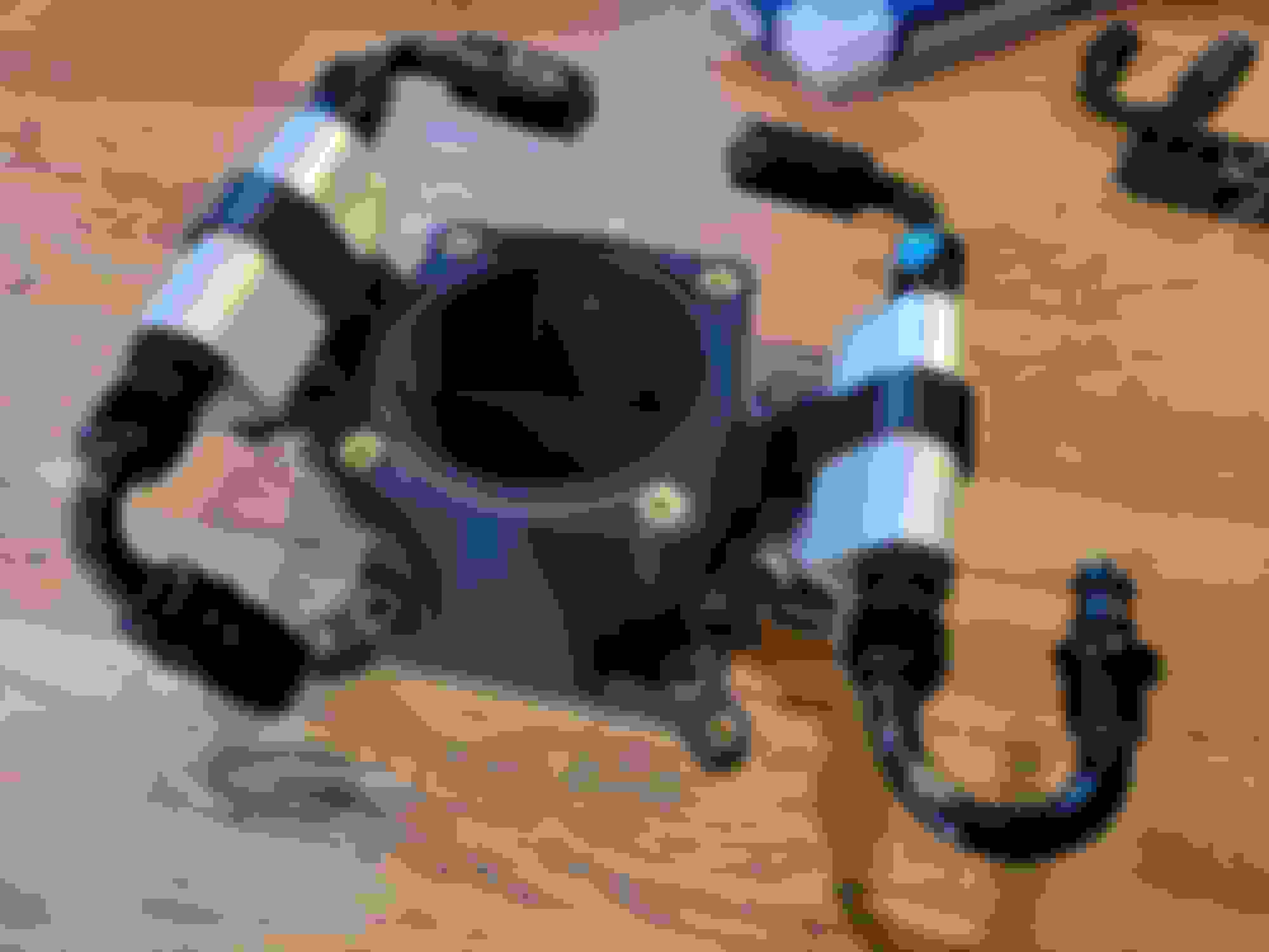
Thank you! And funny you should ask, here's a couple photos of a fast mock-up I was running yesterday (fast as in it doesn't look amazing, but it still took nearly 24 hours).
The printer still needs some more work before it's ready for producing final units, but it's plenty for running mock-up parts. That print there was using one of my "fast, low density prototype" profiles and still used upwards of 700g of material and took approximately 22 hours.
The final unit will most likely be printed in a material produced by Lehvoss (Luvocom 3F) called PAHT-CF 9742 BK. It's a high temperature nylon with 15% carbon fiber reinforcement, and is rated for continuous use at 150C while retaining low creep and excellent chemical resistance. I already have some on the shelf here and testing will of course be done confirm it's suitability, although so far I'm quite impressed. The design will also be getting a heatshield, which I breifly forgot to design, so that should mitigate any remaining concerns for heat related issues.
As for finishing, I don't intend to do any post processing of the raw parts. They'll be utilizing soluble supports (which I didn't use for the mock-up because they're expensive) and that means there isn't any clean up in that regard. Fiber filled materials tend to have a really nice surface finish as it is, and I don't expect the 250 micron layers to cause any issues with flow through the runners. The only work that'll happen after the printing process is complete is annealing the part, dissolving the support material, reaming the injector bosses, and then installing the various inserts.
Worst comes to worst I do have another material I can use (PPS-CF, also by Lehvoss) which is suitable for use at up to 220C and is inherently flame retardant, however it's a very stiff material (not very tough) and that makes me a little iffy on it holding up to any unexpected impacts or backfires. It's also a bit more expensive, although we'll just have to see. I plan on at least doing the initial functional units in PAHT-CF, but if testing proves PPS-CF to be preferable I may transition over to that. Alternatively I can also revisit the idea of casting the part, which actually wouldn't be too difficult other than my lack of a kiln for burning out the positive in the molds.
That's impressive in scale, scope of work, and planning. And at < 0.001" layers for your production build, I completely see your point about not needing finishing. I'm optimistic for durability given your material choice, there are plenty of high performance cars with plastic intakes. And if you run into a structural problem, you can easily modify the design.
There are build threads on here that are aspirational...and that's certainly okay and interesting to see. But this is a level above and you're progressing it quickly. Nice.
Thanks Toruki. I'm also a bit optimistic about the durability of the material in question, although I've seen numerous people use lesser materials and still have no issues (granted not in boost). Either way there will still be extensive testing to ensure reliability.
Also just as a clarification, 250 micron is 0.25mm, or ~0.0098". Perhaps an extra zero just snuck into your reply, but it would be < 0.01" to be correct . Still small enough that I don't anticipate problems, although they are on the larger side as far as a lot of 3D printing is concerned. Reason being is my tungsten carbide nozzle (required for abrasive filaments like fiber fills) is 0.5mm in diameter, so generally the baseline layer height is half that, and therefore 0.25mm. You can deviate up and down from there, but the results are consistent at 0.25mm and it's a good balance of speed and surface roughness.
Excited to say that work will be resuming on the SA in not too long. As seems to be a theme I've been amassing parts over the last few months in preparation for getting the car back on the road, and as of now most of the primary components are in hand.
Regarding the setup, I ended up jumping from the originally planned MaxxECU Sport to the Race model for some extra data acquisition - I'm very exited to put those eight thermocouple inputs to good use. I'm also wiring for some extra sensors including EMAP, turbo speed, and ethanol which, while they may not make the initial build, will eventually find their way into the car. It will also be remaining turbocharged, which had been on the chopping block for a little while there, so I'm rather happy about that. For now it'll be sticking with the same old Borg Warner S251sx, but finally replacing the poorly chosen divided 0.83 AR T3 turbine housing with a 1.06 undivided T3. The hope is to reduce back-pressure a bit (one reason why I'm wiring for EMAP) and help the top end breath better. Previously I had been hitting peak power by 6k or so which wasn't too fun to reel out, though I'm sure the synchros probably appreciated it. The new housing is also a proper V-band instead of that iffy Marmon flange, which speaking of...
...I was finally able to confirm the source of the fire (mostly). A couple months ago I got the time to look into things and crank over the engine, and man alive was it ever full of fuel. Genuinely the most fuel I've ever seen come out of an engine. After some tests I was able to confirm that the injectors were all mechanically intact, so in my mind the only remaining possibility is an ECU or other electrical error. Given the fact that the Speeduino did not have much in terms of faulty sensor protections my theory is that a misbehaving (potentially MAP) sensor was the culprit. Unfortunately I have no proof one way or another, but it's nice to at least know that it wasn't a mechanical failure. The new ECU also has plenty of sensor fault failsafes so I'll be resting easy on that one.
Next, plans have changed a bit with the new intake manifold. I had been running into a few design concerns with the project, then my printer began having issues, and finally when my material didn't ship for two months it more or less sealed the deal for the project to be delayed. Unfortunately the company I was purchasing the material from has opted to stop distributing it, which only leaves one other supplier whom both charges more and is overseas. I took that as a sign to hold off for the time being and just do some fixes to the old setup since it at least works. Because of this, I'm making the new engine harness with injector and throttle body (DBW) bulkheads so that different intake manifold combinations can be easily experimented with. Should make it nice and tidy to swap between different configurations without needing excessively long wires to ensure full compatibility.
Lastly a few notes on the remaining general plan. The vehicle is also being converted to a PDM (in the old sense, there isn't the budget for a solid state fancy one) which will allow all aftermarket relays and fuses to be relocated to a single sealed box. This also means that radiator fan control will be handled by the ECU and no longer a separate box. The radiator fan aside, this has been a major gripe of mine for quite a while with how many relays (and fuses) there are hiding throughout the car. For example, currently if the fuel pump fuse or relay blows I have to pull the storage bin panels for access. There will also now be a clutch switch input (for those fun things that will break my transmission), a CAN gauge integrated into the center console (replacing my AFR and boost gauges with one single unit), as well as a vehicle speed input which I'm very exited about. The idea for VSS is a small box that goes between the speedo gear drive on the tranny and the speedo cable. I'm aware that something like this exists for many old-school American vehicles but I was unable to find one that works with our exact design. Should be pretty simple to make but time will tell. The addition of VSS will allow a handful of extra features including idle up when moving, gear detection (and thereby boost by gear), launch control vs shift cut differentiation, disabling the radiator fan at speed, and more.
Anywho, the plan is to begin vehicle work in just about a week and the goal is to keep moving pretty quickly. The optimist in me says two or three weeks until the first fire on MaxxECU, although realistically if I get there by mid-to-late July I'll be happy enough. In preparation for the project I've also already completed a full base-tune file, so once wiring is done it should be fairly smooth sailing on the configuration side of things.
To wrap up this wall-of-text here's a couple shots of the loot pile as it stands now - no car photos just yet.
Last edited by Benjamin4456; 06-13-23 at 02:10 AM.
Little update on how things are progressing. First off, the ECU is now in the car with the first segment of harness complete. It took some finagling to fit where it would be out of the way but I think it worked out pretty well. I still need to make up a little kick panel so that a passenger can't boot the wiring connectors, but otherwise it should be good to go. The harness I had designed to be in three primary sections; one running from the ECU to the other two primary interfaces, and then one interior and one engine bay section separated by bulkheads/large DTM connectors. The first segment is what is complete as of now, with the bulkhead being terminated and mounted for the engine side as well as the interior.
Before completing the engine side of the harness I've been working on finding everything electrical a home. Mainly that entails the PDM, pedal position sensor, ground bus, as as well as the VSS and WBO2 sensor. The latter I know more or less where they have to be so they don't necessarily have to happen first, but the PDM and pedal sensor are somewhat large and I've been trying to get them mounted before moving forward. I believe the PDM finally has its mount done with just a couple small tweaks left to do, so I'm quite happy about that. As it mounts to the wheel well it was quite the ordeal to get the mounting surfaces to mate correctly. I did use photogrammetry as a poor mans 3D scan, but it only got me so far and introduced a lot of headache along the way. Thankfully the pedal sensor mounts to something flat so it should be a lot more simple.
A clutch switch has also made its way into my car - conveniently Mazda used the same thread size for the clutch pedal stop as the brake light switch, so I just picked up another brake light switch and voila, clutch input! This is part of my goal to have the option to do things like no-lift-shift, launch control, cruise control, etc. even if for now half of those would likely break something in my drivetrain. That short section of harness also will have a flex fuel connector on it (routed to the bin area where my surge tank is) for possible ethanol fueling in the future. Unfortunately here in Oregon e85 is quite uncommon so I doubt that it will make an appearance anytime soon.
The exhaust work for the new turbine housing is also under way, and it was a bit of a surprise to learn that the old and new housings don't share the same inlet to outlet dimensions. I suppose that must just be a thing when changing housings within one manufacturer, whereas here I switched from a genuine Borg Warner housing to an AGP one. The misalignment isn't much though, and an extra 1/4" of spacer was all it took to get in the ballpark. My intake may also be taking a different route although that has yet to be confirmed. I came across an RB Holley intake manifold for sale that I think may work to weld injector bungs to. Still sorting out when to go look at it, but if it works it means I can ditch the injectors in the 3D printed throttle adapter. A little concerned that it may not clear the turbo however, so it may not work at all, we'll have to see.
Lastly I bought some new brake drums with the original intension of swapping my 1980 drums to the FB style with some spare backplates and all. Unfortunately I'm having trouble tracking down all my hardware required for the swap, and I also just don't really want to swap in the first place. Figured I would try installing the FB drums on the SA setup just to see what doesn't fit (I assume it's a clearance issue with the back plate) since they're the same height and diameter. Supposedly Mazda USA will see another shipment of the SA drums in November, although they want nearly 200 bucks a pop for them and I don't know if that's really worthwhile. Food for thought anyhow.
I just swapped a GSL rear end into my 79. I don't know if any of the hardware off of the 79 drums would help, I imagine it's a slim chance, but I'd be glad to donate it. I no longer need it anymore.
I just swapped a GSL rear end into my 79. I don't know if any of the hardware off of the 79 drums would help, I imagine it's a slim chance, but I'd be glad to donate it. I no longer need it anymore.
Envious, haha. I appreciate the offer however I still have all the hardware for the 1980 setup as that's what is installed on the car. Finding the 1980 drums is the tough part. Shoes are still available too which is amusing but oh well.
If anyone happens to have lightly used (still within the wear limit) 1980 drums I could very well be interested in those. Might post a WTB depending on how the FB drums fit and whether I can find all my FB brake drum parts in storage.
Last edited by Benjamin4456; 07-11-23 at 05:29 PM.
My drums being out of spec was the final nail in the coffin for me swapping to a GSL rear. My rear right drum was going through shoes very quickly.
Fantastic work on your build.
Thank you.
I'm trying to hold off spending a bunch on the stock setup since it's pretty likely I'll end up with a 9" or something within a year or so. The new drums and whatnot just have to last until then, but unfortunately they're past the wear spec at this point and need to be dealt with.
Figure it's been two months so I should share a little update. I'll try to get a more in depth one written up with photos sometime soon here but for now here's a bite sized version.
As of a few days ago the car runs again, albeit poorly as I'm very much still sorting out the tune. It has made it around the block, but only just barely. Very excited to hopefully get it driving like it should soon, but there's still lots of work to do. The drive-by-wire throttle is very cool as well but it's cause for some minor headaches too.
The wiring harness took a good lot longer than I expected, although I'm mostly happy with the result so I'd consider it worth the effort. There haven't been any wiring faults/errors either, so evidently my large spreadsheet did it's job. I do still need to complete the wiring branch for the gauge and indicators in the center console but the car can drive without those.
Tonight I'm going to try and get the closed loop idle control online so that it no longer nearly stalls returing to idle after cruise. Once that's sorted and I have my cruise section of the VE table dialed in better hopefully I can take it out of the neighborhood and start dialing in the rest of the map.
This thing has been way more work to get running again than I anticipated. Darn near every bit of free time I've had for the last while has been spent on it, and even then it's still not road worthy. Figured an ECU swap would be simple, heh... Guess I decided to do a bit too much at once, but I'm sure it'll be worth it. I still look forward to figuring out a better intake manifold solution for the 12A, but that's been put on the back burner for the time being.
Like I said I'll try to get some photos up one of these days. It looks pretty similar to the old setup engine-wise, but I'm really happy to finally have tidied up the wiring on the driver's fender with a sealed PDM box. For now, cheers!
Alrighty, finally time for some photos, but first a little update.
Last night I went to check my ignition timing and set the "ignition system delay" value in the computer. Upon clipping onto the leading plug wire I was surprised to see I had no spark. I have quite an old timing gun so I figured it might just be acting up, so I tried the the other wires and, well, they worked fine. So I unplugged the leading 1 coil and, what would you guess, the car ran exactly the same. Evidently I've been missing my leading spark this entire time...
So suffice to say that explains quite a lot. After much coil swapping I determined that I do indeed have a dead coil, so now I am trying to track down a couple replacements as quickly as possible. For the time being, however, I have swapped my coils around so that the good coils are back on the leading and surprise surprise, the car runs much better. Can't believe I never noticed it before, but it sure as heck explains a lot of the oddities I was experiencing. For now I'm continuing to tune with a missing trailing coil since it doesn't make a huge difference, and so far things are doing much better. Hopefully I can get my hands on a new coil sometime this next week (IGN1As are tough to find local).
So now back to the main, in depth, progress update. Getting this car running again took a lot more effort than I anticipated. Originally I thought I could have it running by the end of July or perhaps even sooner, and while I suppose a month off isn't a horrendous underestimate for a project car, it's still quite a significant one.
The first thing after getting the ECU mounted up and figuring out the locations of a few items was to make new fuel hard lines. I learned my lesson from last time in trying to work with 3/8" steel tube, so this go around I opted for some nice NiCopp alloy tubing. Still a bit annoying to work with but much better than straight steel. Both the feed and return lines were replaced, even though I had previously run a new 3/8" return. Reason being is that I couldn't put a bead on the steel line so I had to use compression fittings on each end, which I really wasn't too crazy about. The NiCopp on the other hand is soft enough to use a bearing bead roller so I could forgo the old compression fittings.
The next thing to do was not at all in the plan, and that was rust repair. Overall this chassis is pretty straight, and the underbody is mostly immaculate. The interior on the other hand is a different story (dang sunroof). What began as an attempt to tighten a loose seat bolt turned into a multi-week rust repair episode. It's not my finest work, but I was able to take care of the worst of the rust and fix the few holes that had appeared in the floor. At the recommendation of a friend I used a product called Vulkem 116 as the sealant for floor patches. It's an interesting caulk to work with and it certainly takes a while to set up, but seems tough as nails now that it has.
With that out of the way I could get back to wiring, which certainly felt like the longest part of this whole project. Many late nights were spent slowly chipping away at the new harness, which compared to the old one was over double in wire count. Most wires were from the 47-pin bulkhead for the ECU, but many more were for other intra-engine-bay things such as the many grounds and outputs from the PDM.
Overall I'm happy enough with the final result, although there are a handful of changes I wish I could have made. First off, the nylon braid works but it's really not the best thing to use. Had I another few hundred dollars to throw at it I would have used proper heat recoverable boots and sheathing, but perhaps that will happen next time. I also wish I put the coils on their own sub-harness like I did with the fuel injectors and DBW throttle. I accidently made the coil branch shorter than I wanted and this could have been an easy fix had it been on a separate sub-harness. It would also allow the coils to be relocated in the future if I ever wanted to do that for some reason.
It would appear that I never took a photo of the completed harness, so here's a few in-progress photos of the wiring instead.
One of the last major things do figure out was the new fuel injection adapter thing (I still don't know what exactly to call it). The old one was designed for a different throttle body, and also was set up for an idle valve and to accommodate the factory phenolic carburetor spacer. The phenolic spacer was going away because I could never get it to seal correctly with boost, and the idle valve wasn't needed anymore thanks to the new electronic throttle body. I ended up redoing the whole thing from scratch and made a number of fixes along the way to improve it over the old one. I would certainly prefer to not use it at all, but I have yet to sort out a different intake manifold solution for the 12A.
Unfortunately there were a few unexpected shortcomings with the new design. First was that I did not anticipate a clearance issue between the primary fuel rail and my coolant temperature sensor, so then the fuel rail had to move. Then I decided the secondary fuel rail was too close to the turbo so it had to move, but then of course the throttle body motor was in the way. So after a good bit of iterative design I finally sorted out something that would clear all the obstacles while still being reasonable given all the other constraints. Had to also switch to a series fuel rail setup because I couldn't fit a fuel return line on the back, once again because of that darn coolant temp sensor being in the way. All in all it works though, so I'll just be happy with that for the time being. Oh yeah, and then I cracked my intake manifold installing the new studs. Fun times.
At this point I've run out of photo room in this post, so I'll continue the last little bit in a follow up here momentarily.
Most of the engine related bits were wrapped up by that point with just the fuel lines and a few straggler wires to be put together. Somehow upon the first power-on nothing went awry, which, given how much had been done in a "short" period of time by my sleep deprived self, was really quite a miracle.
Fast forward a bit and I also got my new center console put together. I'm going to pretend it's still a prototype as there are a handful of things I would like to change, but realistically it'll probably stick around for a while until I have time to mess with it again. I'm quite happy to now have a multi-function gauge as well as my three warning/multi-purpose lights. Heck I even have a check engine light now and I'm probably more excited about that than I should be. I still need to wire for a few switches which will fill those remaining empty holes, but otherwise it's functionally complete.
For now I think that's really about it. Lots of tuning yet to do and so far the car has only been up to about 30mph (without leading ignition mind you). I obviously glossed over lots of little things that inevitably took a good bit of time to sort through, but I believe I covered all the major points.
I'll go ahead and throw a few more assorted photos in below here, but otherwise cheers and happy rotoring!
I commiserate with your floorboard rust problem. Mine sat for 10 years with essentially no door seals. I should have removed the carpet and floor plugs years ago to prevent the water from sitting there chewing on my steel. Mine was a lot more extensive. I got the driver's side done, was working on the passenger side until it got too hot to work outside (Texas...) and I discovered the outboard seat mount pretty much beyond repair. I'm stalled until I decide what to do there. I could probably fabricate one, but I'd rather find a junked chassis with a good floorboard section and steal that.
I really love the 3D printing aspect of your build. That's such a fascinating technology. I've got a 3D printer (an Anchormake M5) and it's incredibly fun to use, but they don't yet have an all-metal hot end for it yet (it's coming) so I can't do nylon or other heat-tolerant plastics. Still, already designed and made some bits and bobs for my AE86 (screw hole plugs, seat recline handles, cupholder) and my Crown Vic. Very likely I'll create some parts for my 7 - particularly given how many small plastic parts are NLA.
Hey Richard, thanks for checking in. It's nice to know folks haven't forgotten about the car.
I've unfortunately been rather busy lately with life in general and haven't made much time to work on the car, let alone document it. I'll do what I can to get a summary of what's been done since the last update posted here at some point, although there isn't a whole lot. I do post a little more frequently on my Instagram, Ben_SA7, although not nearly as in depth as I do here and at present it's more just day to day items.
I certainly have quite the list of stuff to do however. At present I am working on getting an 89 NA transmission rebuilt for the car (my current transmission has some extremely unhappy bearings) and a friend has began assembling a shortened Ford 9" rear end. Plenty of other work on the docket too, just need to make the time.
 03-12-23, 12:40 PM


 . Still small enough that I don't anticipate problems, although they are on the larger side as far as a lot of 3D printing is concerned. Reason being is my tungsten carbide nozzle (required for abrasive filaments like fiber fills) is 0.5mm in diameter, so generally the baseline layer height is half that, and therefore 0.25mm. You can deviate up and down from there, but the results are consistent at 0.25mm and it's a good balance of speed and surface roughness.