
85' Stripped Corner Carver


Joined: Mar 2001
Posts: 31,851
Likes: 3,241
From: https://www2.mazda.com/en/100th/
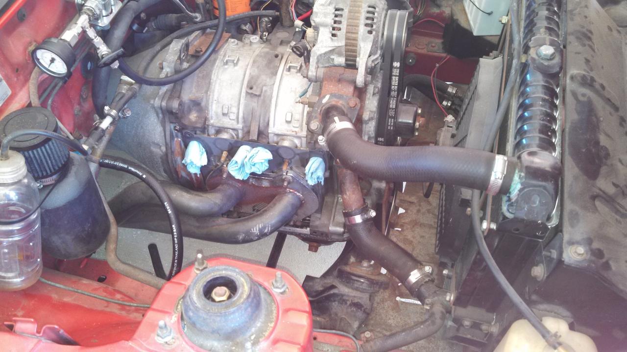
Hrmm... Could I just remove the hose from the hard line to the intake manifold (the one that comes from the brake booster) and cap the port on the intake? That way I am not so much testing the booster but ruling out that as the cause of not idling.
Also, can I perform a compression test without the intake manifold and carb installed since you don't need fuel and just air?
I was planning on taking the carb back off and completely taking it down, ordering a seal kit and rebuilding it. A master rebuild kit is only $75 and includes pilot needles/seats and accel pump diaphragms as well as gaskets.

Thread Starter
Full Member
Joined: Apr 2012
Posts: 201
Likes: 0
From: Louisiana
Edit: Actually, after looking at it further I may not. The kit includes the needle valve which I don't think I need as mine is clean and works. I am gonna separate the brake booster and see if that helps, then do a compression test after that. If neither turn anything up I will just wait for the wideband.
Last edited by Shrimp; Jun 26, 2013 at 12:48 PM.
Thread Starter
Full Member
Joined: Apr 2012
Posts: 201
Likes: 0
From: Louisiana
Same result without the intake on there so.... I dunno. The idle speed screw was all the way in so maybe it wasn't much of a restriction to begin with.
Edit: Re-read it... again.. because I missed a step.
With the valve open on the wide I am within the 30-35 PSI range. When the valve is closed I am around 70-80 (for all three faces?) but I think I am a little low because the cranking speed is probably not quite 250 (gonna put a battery charger on it and see if it rises). FSM says pressure needs to be @85 PSI.
Last edited by Shrimp; Jun 26, 2013 at 04:28 PM.
Thread Starter
Full Member
Joined: Apr 2012
Posts: 201
Likes: 0
From: Louisiana
Re-jetted to leaner pilot, fuel and way leaner air.
The car will idle around 850 or so with the starter system engaged but dies as soon as you release it. What does that tell me? I think it would do that even before I re-jetted I just never tried to drop it that low because it would kill when I released the starter whereas if I had the idle speed cranked up all the way I could release the starter and it would run at around 1500 rpm.
I also put the battery charger on the car at cranking amps and got a reading of 75-80 for the front and back overall, then front with the valve open on the tester was around 30-40 psi and the back was 50+. Each rotor had even compression across the three faces.
I am still trying to identify the damn regulator I have but none of the numbers on it match up to anything on the Holley site, they must have changed their damn part numbers the bastards. When the return is hooked up I have trouble setting the regulator to anything above around 3 PSI but with the return blocked I can set it anywhere from 2-6 PSI or so.
Last edited by Shrimp; Jun 26, 2013 at 06:02 PM.
Thread Starter
Full Member
Joined: Apr 2012
Posts: 201
Likes: 0
From: Louisiana
Read a couple posts with people having this same issue. Carb runs great just won't idle and idles with the choke open.
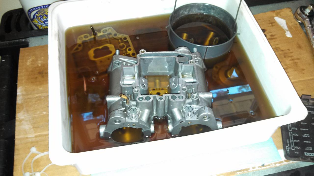
Only people I found that fixed it did a complete breakdown and rebuild of the carb. I've got it down to bits and the main body soaking in some carb cleaner right now. Gonna get a gasket kit and new pump diaphragm (I wasn't getting any fuel on throttle through the pump jets).
Only people I found that fixed it did a complete breakdown and rebuild of the carb. I've got it down to bits and the main body soaking in some carb cleaner right now. Gonna get a gasket kit and new pump diaphragm (I wasn't getting any fuel on throttle through the pump jets).
Thread Starter
Full Member
Joined: Apr 2012
Posts: 201
Likes: 0
From: Louisiana
Broke out what I had left of the old rebuild kit. Still have the throttle shaft seals, pump nozzle o-rings, pump-weight o-rings, pump nozzle seals, etc... All the small stuff that is still good inside the carb so I have extras of those. I may go ahead and replace it all since I do have those.
I also wasn't getting any fuel through the pump jets (they were not clogged) so I am guessing I had the shaft length set incorrectly (probably was just barely touching the diaphragm) which is most likely the cause of the low end bog that I was having when it was running.
I am gonna let everything soak until the new rebuild kit gets here (I tore the pump gaskets when I took it apart) then rejet it to what mikuni recommends. By that time I should have the wideband installed and running.
Thread Starter
Full Member
Joined: Apr 2012
Posts: 201
Likes: 0
From: Louisiana
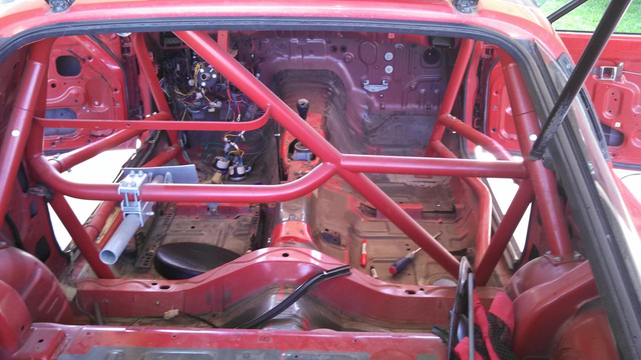
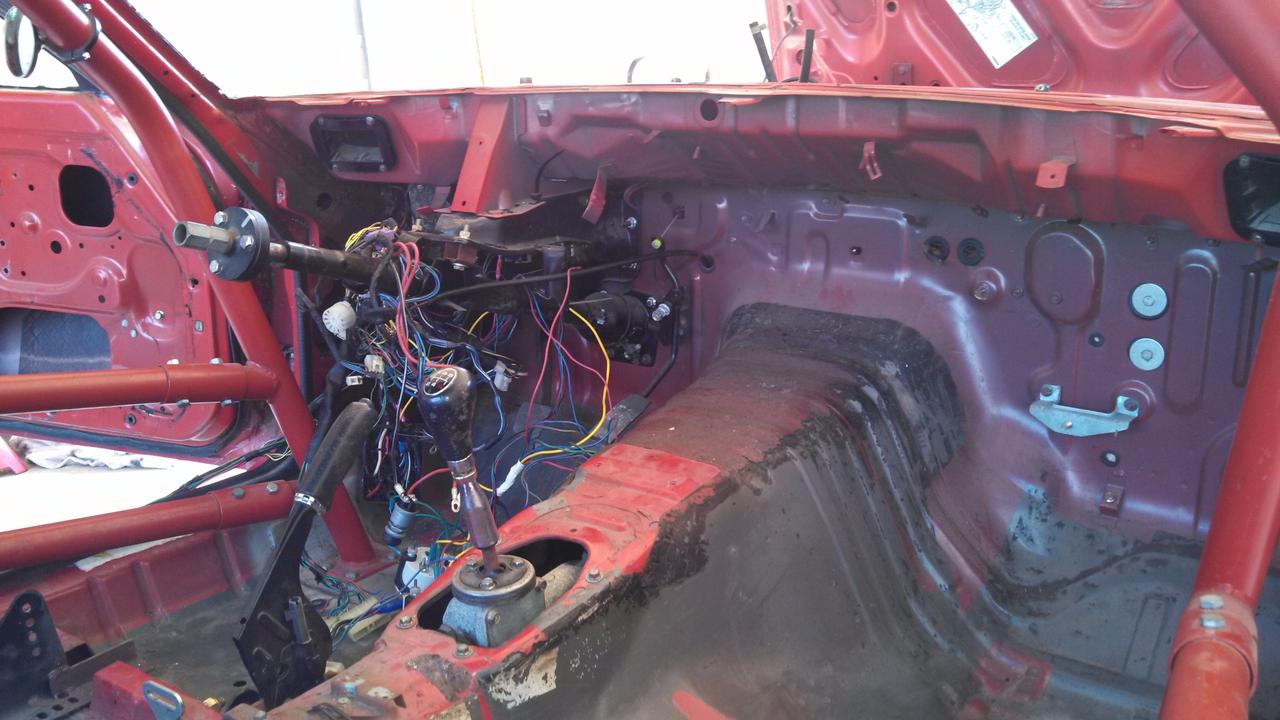
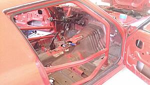
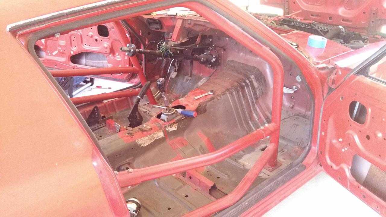
Took off the broken windshield tonight. Also took out the dash I had made. I am gonna put a bar in the front to tie in the two front bars on the roll cage and also to act as a mount point for a new dash. Also trying to pick out a good tach and speedo.
I am thinking of tackling to task of rewiring the car to clean out all the mess of wires I don't need. All I should need is brake lights, rear hatch, and gas hatch. I have no headlights or dash or a/c.
I am thinking of tackling to task of rewiring the car to clean out all the mess of wires I don't need. All I should need is brake lights, rear hatch, and gas hatch. I have no headlights or dash or a/c.
Thread Starter
Full Member
Joined: Apr 2012
Posts: 201
Likes: 0
From: Louisiana
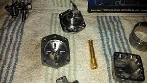
Ha! I've been meaning to check the diaphragm for the accel pump since I took it apart. I made sure to take it out in the order I had the parts in so I could go back and check.
So the diaphragm was in backwards, with the piston sticking up and the spring around it. No wonder I didn't get any gas on throttle and had a bog. Hopefully when I put it back together correctly it will work!
So the diaphragm was in backwards, with the piston sticking up and the spring around it. No wonder I didn't get any gas on throttle and had a bog. Hopefully when I put it back together correctly it will work!
Thread Starter
Full Member
Joined: Apr 2012
Posts: 201
Likes: 0
From: Louisiana
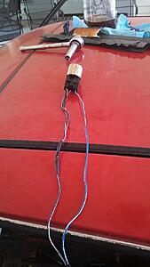
I traced out and ID'd most of the stuff I need and what I don't.
There are a few items I am not sure about such as this:
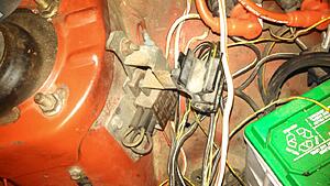
The positive side of the battery goes to one side of it, then it splits to the 40A electric fan relay and the main power cutoff key (outside the car race thingy, not sure technical term).
The only other thing I think I need to figure out is where the L and R terminal on the back of the alternator go. I found the page in the FSM but I don't think I understand it.
That and decipher the brake pedal switch and how I need to wire that to the brake lights.
The rear and gas hatch are easy, just supply 12v.
I am going to finish figuring out what I can tomorrow and try and determine the best fuse block for my needs.
Thread Starter
Full Member
Joined: Apr 2012
Posts: 201
Likes: 0
From: Louisiana
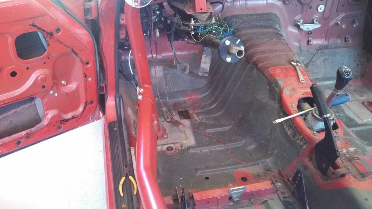
Traced out everything, or at least I am rather sure I have.
Only two things that use a relay are the electric fan and the Holley fuel pump it seems. The starter has a wire that leads straight from the start button and didn't have a relay so I have to assume it doesn't need one (that and it has a large lead coming from the + side of the battery).
I still haven't ID'd the box in the post above. I described it to my dad but he doesn't know what it is, but he hasn't laid eyes on it either.
There were so many unnecessary splices that lead to nothing or are just poorly thought out.
I think I can use an 8 circuit fuse box, if not smaller though. I haven't looked at the brake switch, that's next.
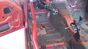
A lot of this will go away:
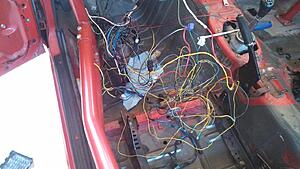
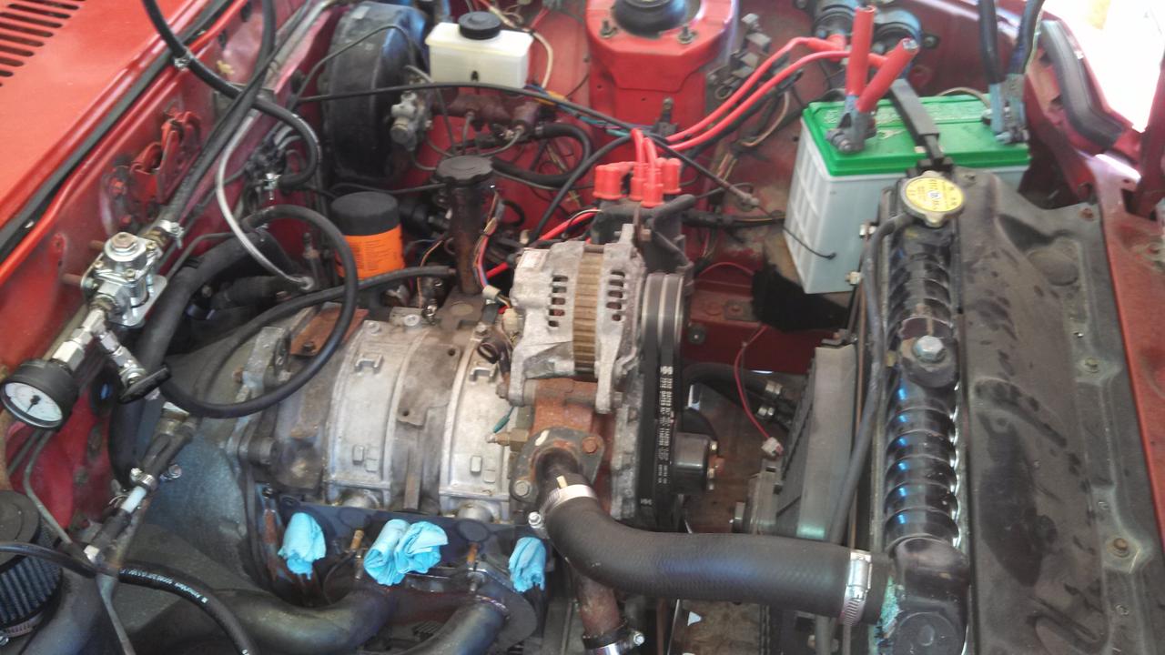
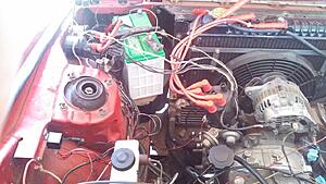
Nothing but the needed wiring in the engine bay, sensor wires laid over to the right side as well as the starter wire.
Only two things that use a relay are the electric fan and the Holley fuel pump it seems. The starter has a wire that leads straight from the start button and didn't have a relay so I have to assume it doesn't need one (that and it has a large lead coming from the + side of the battery).
I still haven't ID'd the box in the post above. I described it to my dad but he doesn't know what it is, but he hasn't laid eyes on it either.
There were so many unnecessary splices that lead to nothing or are just poorly thought out.
I think I can use an 8 circuit fuse box, if not smaller though. I haven't looked at the brake switch, that's next.
A lot of this will go away:

Nothing but the needed wiring in the engine bay, sensor wires laid over to the right side as well as the starter wire.

Last edited by Shrimp; Jun 29, 2013 at 04:03 PM.
Thread Starter
Full Member
Joined: Apr 2012
Posts: 201
Likes: 0
From: Louisiana
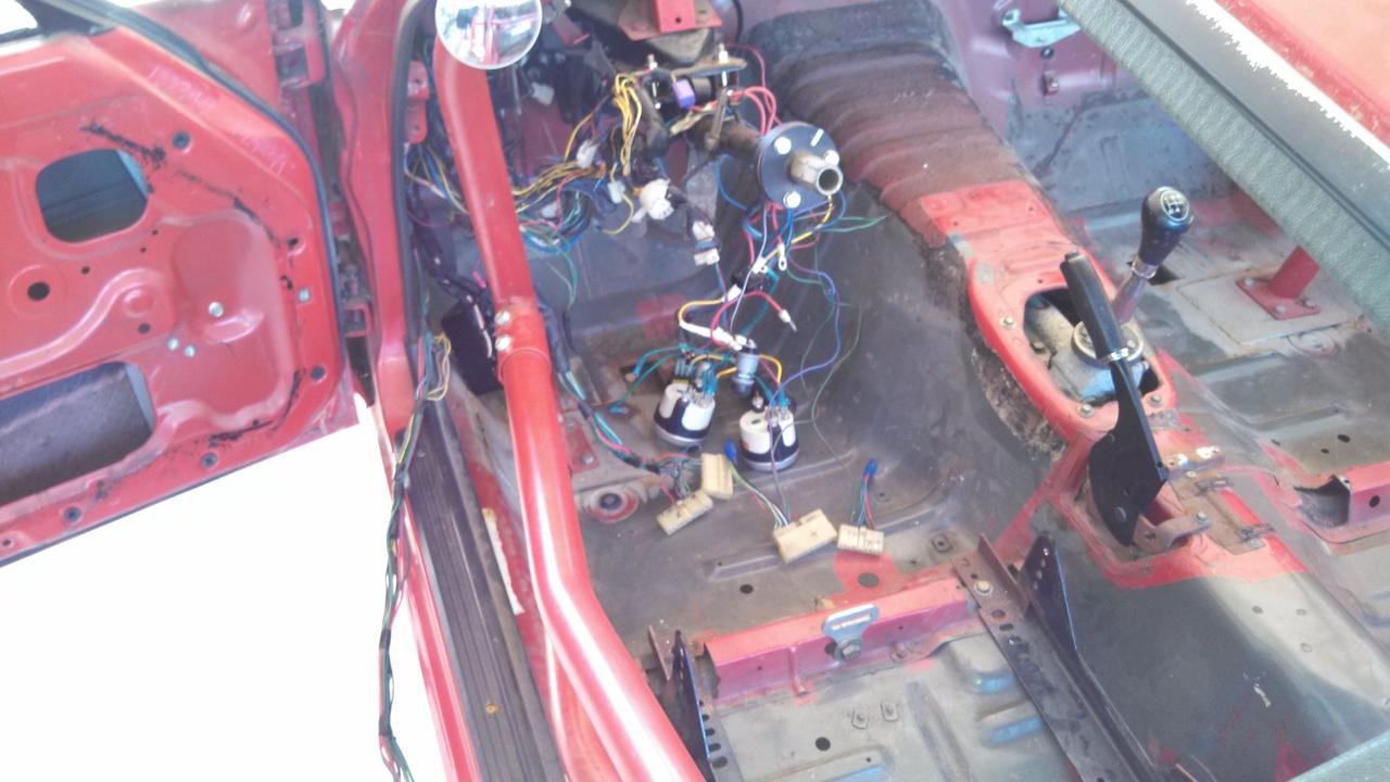
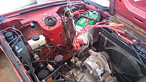
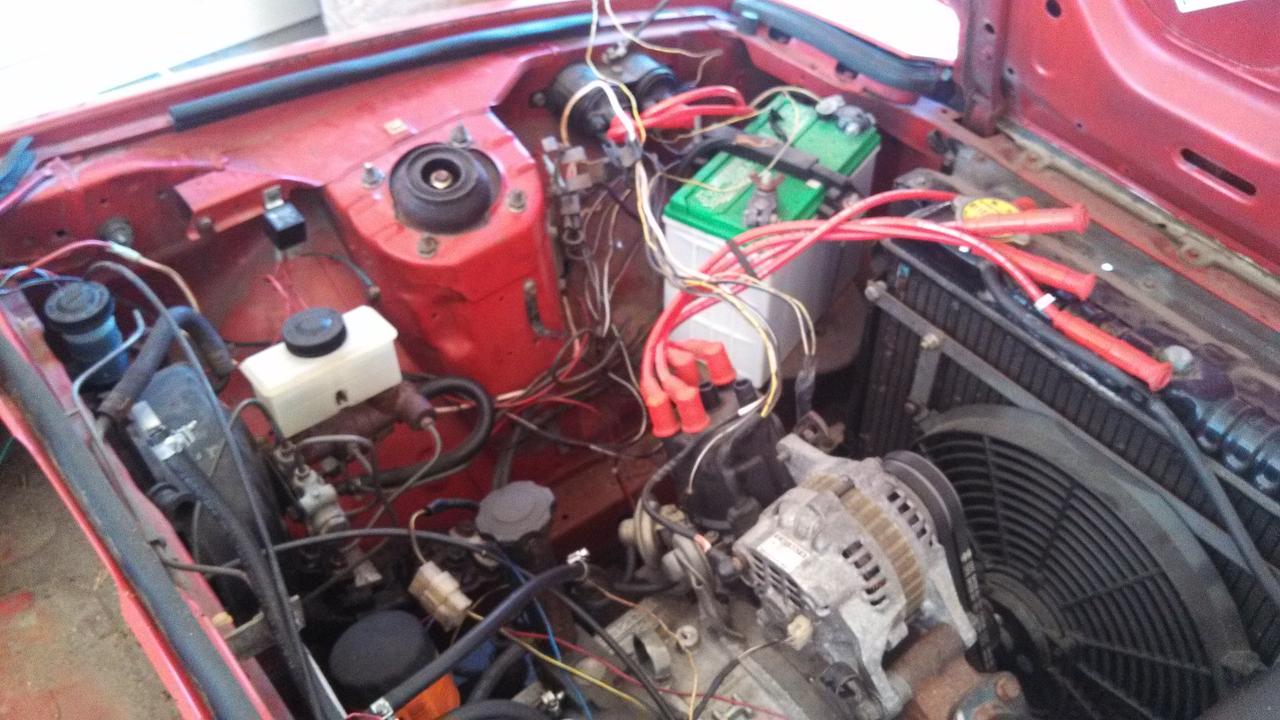
So from what I can tell, using what little knowledge of how electricity works I have, the OEM fuel pump relay has been re-wired to act as a pass-through for 12v. The fuel pump was run off a 20a mil. switch through a 20a fuse, hence no need for the relay. I guess the guy who owned it before me didn't want to go through the trouble of tracing out the wires and running a solid wire so you just jury-rigged everything.
Same for the brake lights and the gas hatch and back hatch, it was all run through the OEM harness. Molex plugs with 15 wires going in had 1 coming out on the other side. It was just a mess. Tons of splices that led to nothing and didn't need to be there anymore, etc.
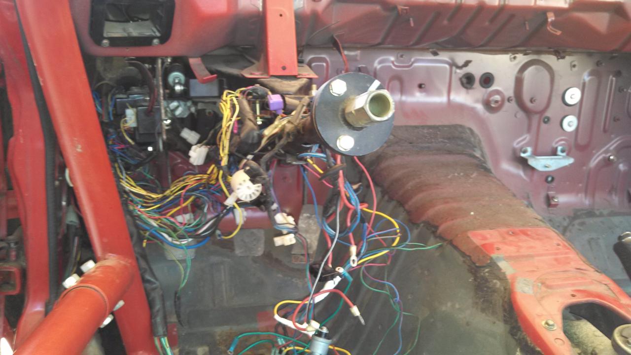
What you see is the brake light circuit on top of the steering column, two incoming powers for either side of the fuse block off the main cutoff outside the car and the fan 12v input to the relay.
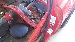
Fuel pump circuit with jury-rigged relay.
This being my first re-wire of a car I have a few questions, and I was hoping you guys could help me out:
Do I want to fuse EVERYTHING? The distribution system is run straight off the main cutoff and does not have a fuse. I did not make it this way, the car has BEEN that way. Is this OK? The OEM fuse block has the "Engine" labeled as a 20A fuse.
There is a circuit labeled "Opener" that gets a 20A fuse. Are these the hatch solenoids?
The only other question I have is do I run a 10A circuit or a 15A circuit for the brake lights? No hazards, no illumination for headlights, just brake lights. Fuse block cover has "15A Hazard" and "10A Tail Illum" circuits labeled.
I think all I need is a 4 circuit fuse block, someone please correct me if I am wrong.
As I see it, all I need is:
1. Engine circuit (20A for dizzy system?)
2. Brake lights (either 15A or 10A?)
3. Instruments
4. Hatch solenoids
The only other thing I can think of that would need a circuit is the starter, but from what I can tell it gets power straight from the battery and has a signal cable that tells it when to turn on (or am I wrong?).
Thanks for the help you guys have given so far.
Same for the brake lights and the gas hatch and back hatch, it was all run through the OEM harness. Molex plugs with 15 wires going in had 1 coming out on the other side. It was just a mess. Tons of splices that led to nothing and didn't need to be there anymore, etc.
What you see is the brake light circuit on top of the steering column, two incoming powers for either side of the fuse block off the main cutoff outside the car and the fan 12v input to the relay.

Fuel pump circuit with jury-rigged relay.
This being my first re-wire of a car I have a few questions, and I was hoping you guys could help me out:
Do I want to fuse EVERYTHING? The distribution system is run straight off the main cutoff and does not have a fuse. I did not make it this way, the car has BEEN that way. Is this OK? The OEM fuse block has the "Engine" labeled as a 20A fuse.
There is a circuit labeled "Opener" that gets a 20A fuse. Are these the hatch solenoids?
The only other question I have is do I run a 10A circuit or a 15A circuit for the brake lights? No hazards, no illumination for headlights, just brake lights. Fuse block cover has "15A Hazard" and "10A Tail Illum" circuits labeled.
I think all I need is a 4 circuit fuse block, someone please correct me if I am wrong.
As I see it, all I need is:
1. Engine circuit (20A for dizzy system?)
2. Brake lights (either 15A or 10A?)
3. Instruments
4. Hatch solenoids
The only other thing I can think of that would need a circuit is the starter, but from what I can tell it gets power straight from the battery and has a signal cable that tells it when to turn on (or am I wrong?).
Thanks for the help you guys have given so far.
Thread Starter
Full Member
Joined: Apr 2012
Posts: 201
Likes: 0
From: Louisiana
Some more staring at the electrical drawings and it all becomes clear.
The thing I was trying to identify above is a Fusible Link. A quick wikipidea search tells me it's there so that the wires burn up before the rest of the system does. Sounds like a good thing to me, that's staying. That also tells me I don't need to fuse the 40A relay for the electric fan.
Also determined that the brake light circuit is 15A and the hatch solenoid circuit is 20A.
The "Starting System" (which is the main wire going to the starter and the input wire coming from the ignition) and the "Emission System" (which as far as I can tell is the distributor and ignition coils) don't have fuses.
So I need
1. 15A circuit for Brake Lights
2. 20A circuit for Fuel Pump and for for 12v to alternator T plug for BW wire (choke and check relay delete since I am running so little stock)
3. 20A circuit for Gas/Rear Hatch Solenoids
4. 15A circuit for 12v input to instruments
4 circuits
Going to get started on the instrument panel next. I think I will need to get the car on a rack to remove the exhaust so I can weld the bung to it.
Last edited by Shrimp; Jun 30, 2013 at 09:50 PM.
I just finished wiring my FB racecar (https://www.rx7club.com/build-thread...-build-992966/) go to page 4 to see images. I have the following circuits:
Start (momentary push button switch)
Fuel Pump x2 - each Carter Pump is switched separately
Ignition - power to the MSD, Tachometer and Volt meter
Brake Lights
Tail Lights - running lights for racing in the rain
Windshield Wipers - High and Low speeds
Radiator fan
Defroster blower (rain racing)
Helmet blower
Cool shirt pump
Tachometer
Adjustable RPM switch (for shift light)
Shift light
Low oil pressure light
Instrument lights - night racing, rain racing
Coil wires from the MSD
Distributor Pickup to the MSD
Batter wire to the Starter
Charge wire from the alternator
You may not need all of this but for my racing I find all of this necessary. I have 20A fuses on most of this stuff. In 8 years of racing I have never blown a fuse. I used Microsoft Visio to design and document the wiring harness. I also used color coded wiring for all circuits.
One of the things that I have found extremely important are good ground points. I welded 1/4" bolts to the car in several locations. Specifically the passenger foot well, left rear roll cage mount and the right front frame rail near the radiator. This allows me to have local grounds for the various circuits.
All connections in my harness are soldered and shrink sleeved with connectors at various locations so I can service components (dash, gauge and switch panels).
For fuses I use a Moroso fused switch panel (part#74134) and would recommend part#74134 to you because it combines a start button and fused toggle switches. I used a buss block located behind the dash to organize and distribute power. This really simplified the wiring process.
Thread Starter
Full Member
Joined: Apr 2012
Posts: 201
Likes: 0
From: Louisiana
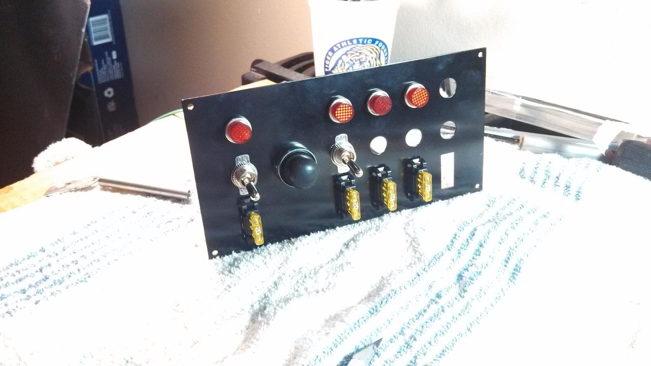
I got the one with the starter on it like you suggested. I had all the switches, but this will combine them into one panel and be easier to wire up in the end. The one thing I don't like will be having to turn on my brake lights or hatch solenoids but I think I can just take the switch out the loop (could only get a front on pic of it).
I've been following your build, you've got a great car and do some amazing fab work.
I've been following your build, you've got a great car and do some amazing fab work.

On my race car, the hatch solenoid was removed and I used a key to open it from the outside. So that the key wasn't lost, it was safety wired with one end pop riveted to the back of the car. I also had a spare key in the tool box.
Thread Starter
Full Member
Joined: Apr 2012
Posts: 201
Likes: 0
From: Louisiana
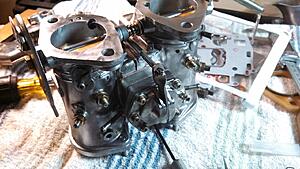
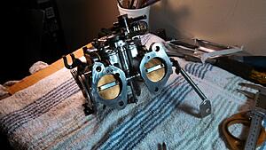
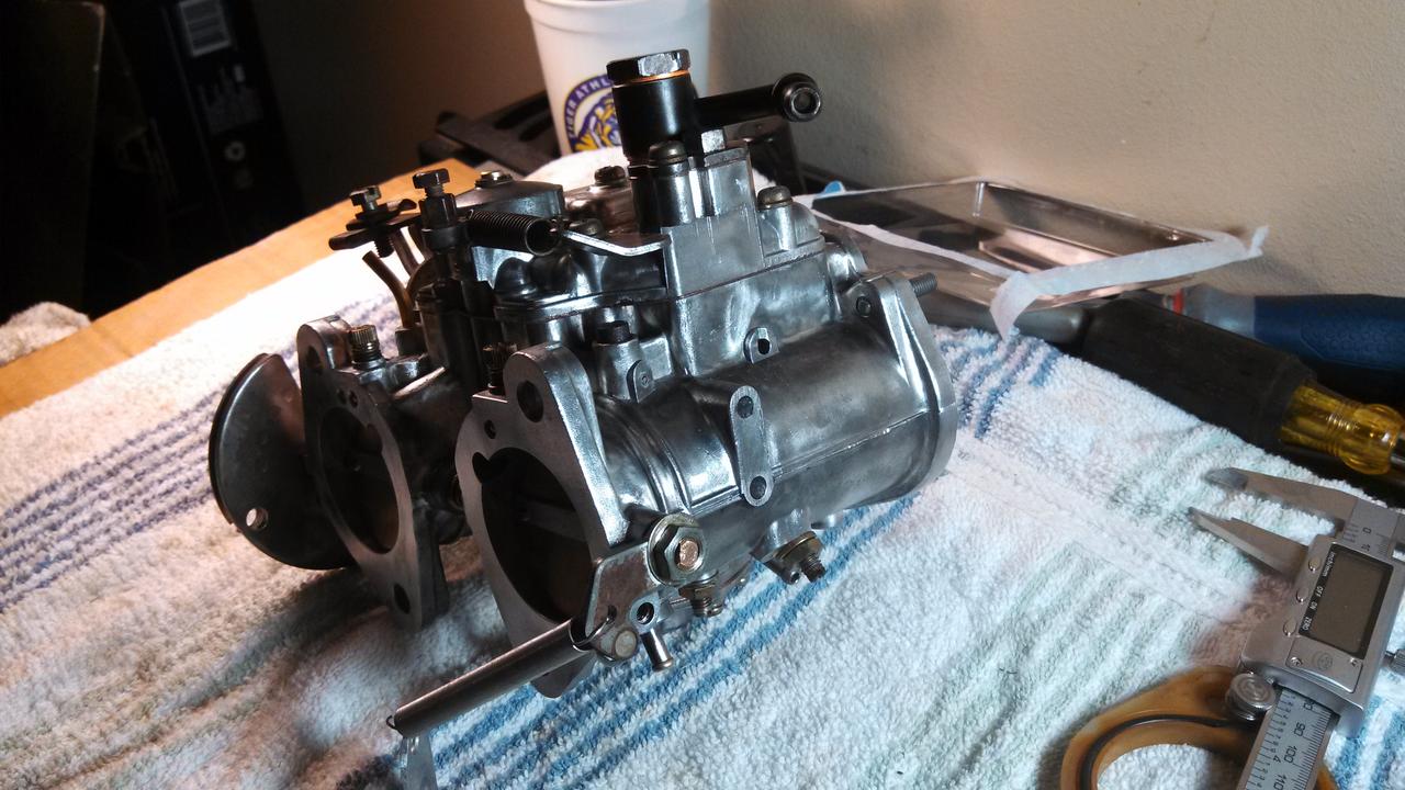
Carb rebuild kit came in.
Pulled the parts out the soaking carb cleaner and cleaned them with the clear carb cleaner. Two pieces had what seemed to be a thin zinc coating that started to rub away when I wiped them down. Cleaned up most of the corrosion on the outside of the carb with a wire brush and dremel/bench wire brush for the big parts.
I will be putting it all back together tomorrow. The fuse panel should be here tomorrow as well. Should I use anything to help the gasket come off if I ever need to take the carb apart again?
Also the silicone spacers are yellowed and the o-rings don't look like they are thick enough to make a good seal between the carb and the intake manifold. I was curious if anyone know where I can get some new ones. We should have a CnC mill on the way at our shop so maybe I can make some new ones if I can't find them.
Last edited by Shrimp; Jul 2, 2013 at 10:40 PM.
Thread Starter
Full Member
Joined: Apr 2012
Posts: 201
Likes: 0
From: Louisiana
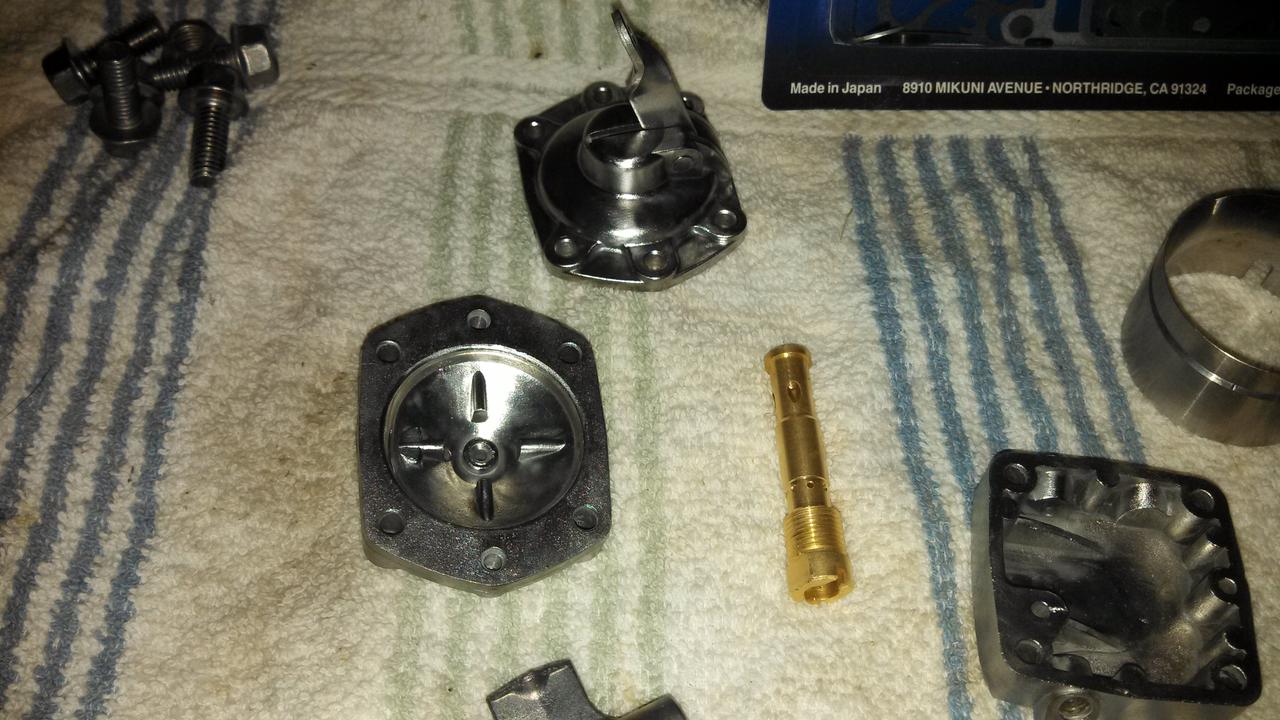
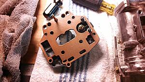
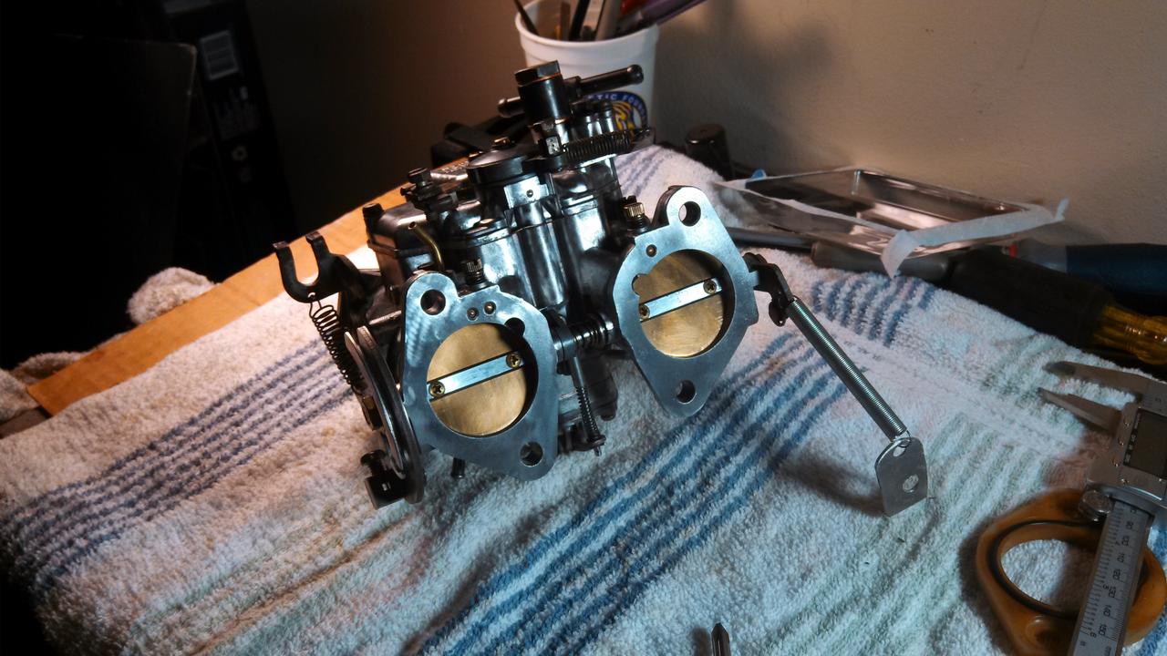
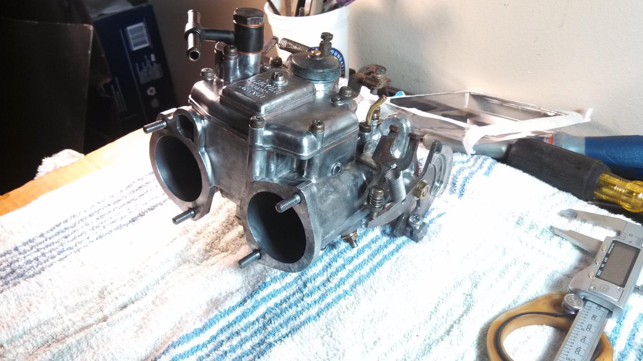
Gave everything the shine treatment as best as I could. Some of those nooks and crannies are hard to get into.


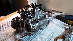
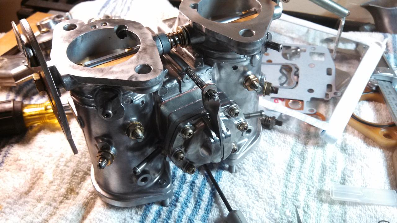
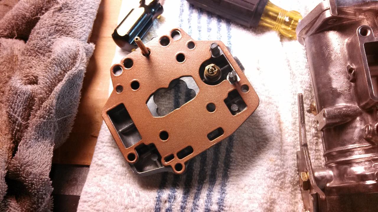
I used copper gasket spray on all the new gaskets and I went ahead and used the entire kit this time, replacing everything that came with the kit.

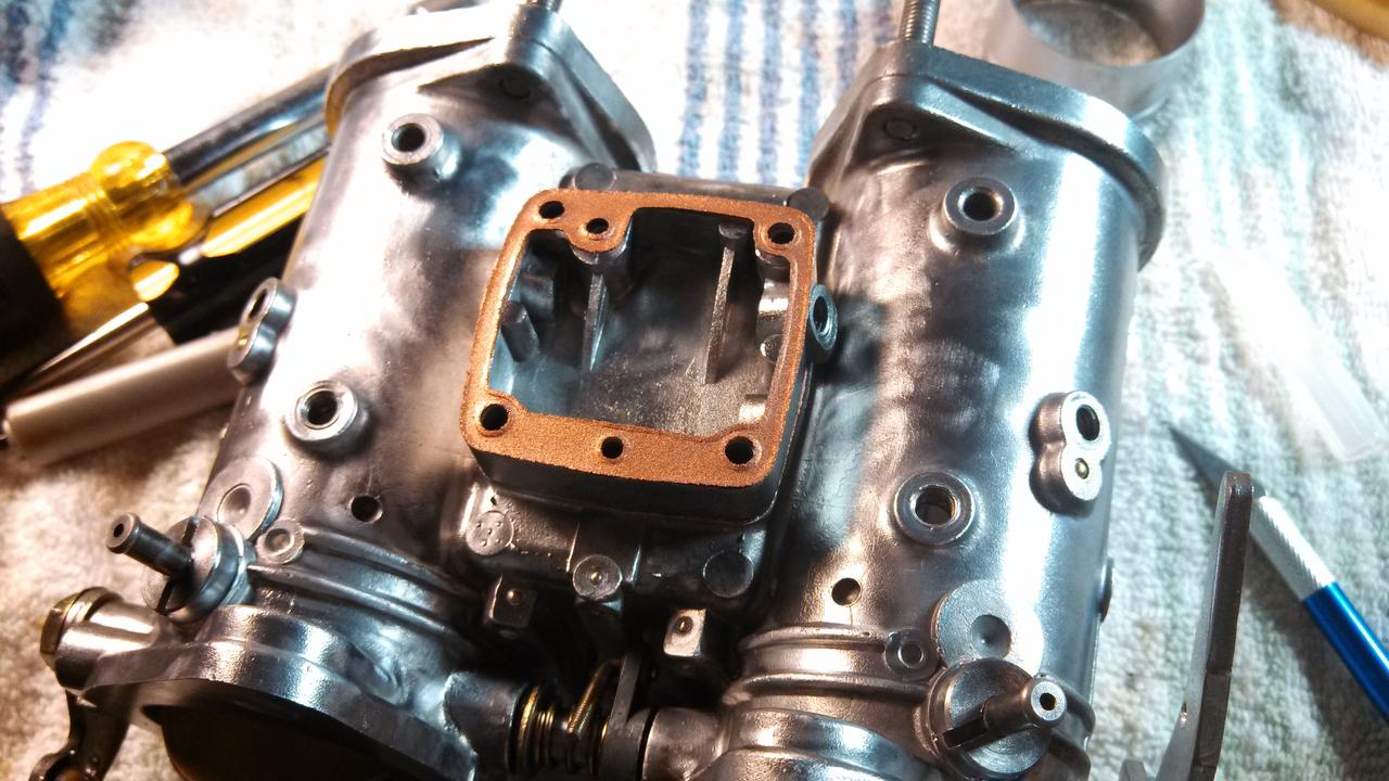
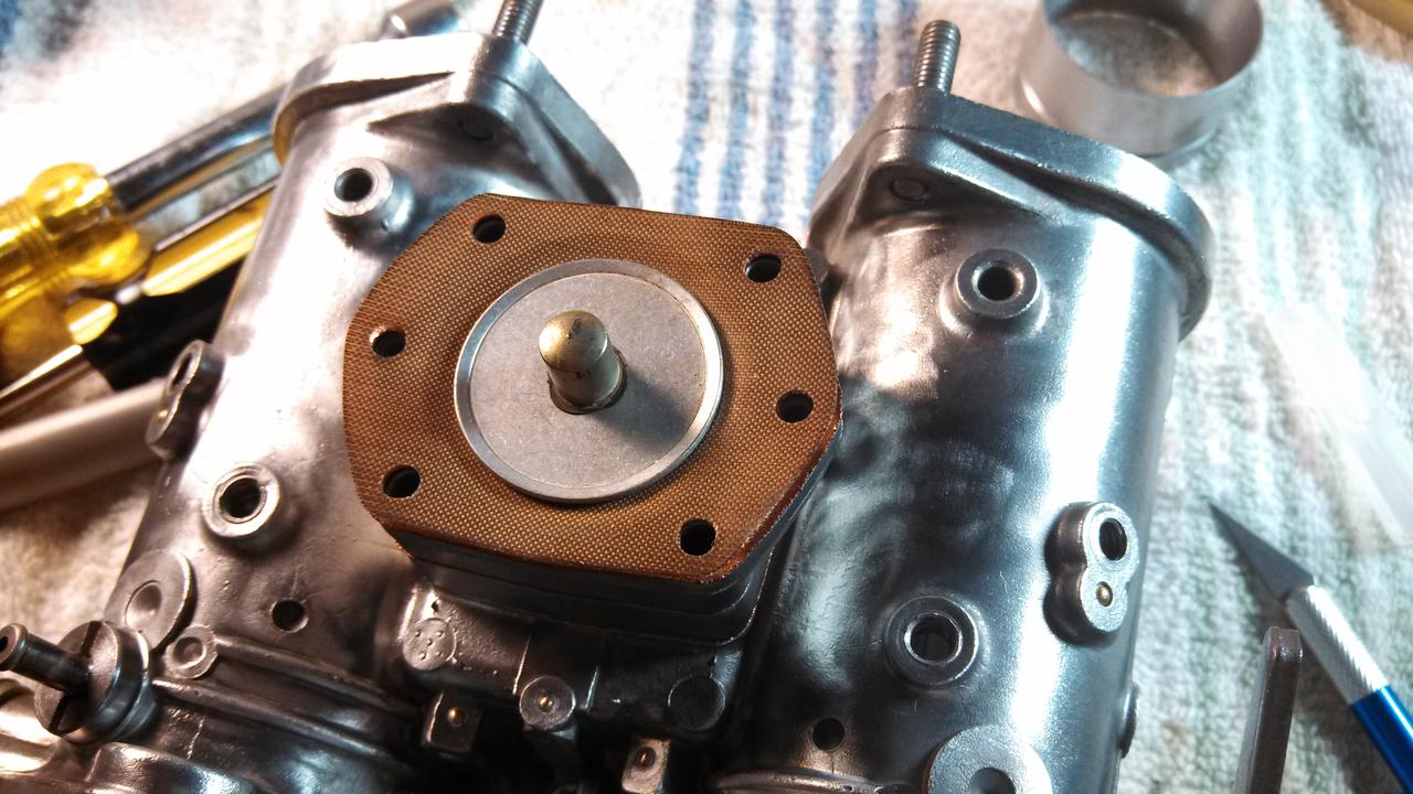
Yes, I put the diaphragm spring in. I just snapped the pic before I did.

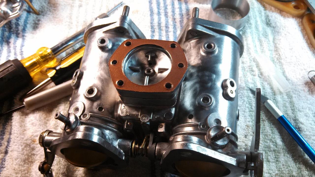
Once the accelerator pump was rebuilt I made sure the diaphragm was pumping. Getting squirts of air through the pump nozzle!
The o-rings for the pump nozzle screw were worn to ****. They came out shaped like a countersink screw head instead of round. All the other o-rings looked in good shape but slightly hardened and deflated. They probably could have been re-used but I have more from the last kit I didn't use if I need them.
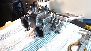
Filled two holes that are "closed" by the venturi. There is a very small crack around the venturies when they seat inside the carb as they go in there quite easily. It probably is barely enough to let a tiny amount of air in, if any, but I filled them with RTV anyways.
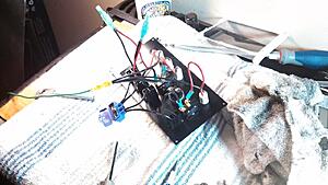
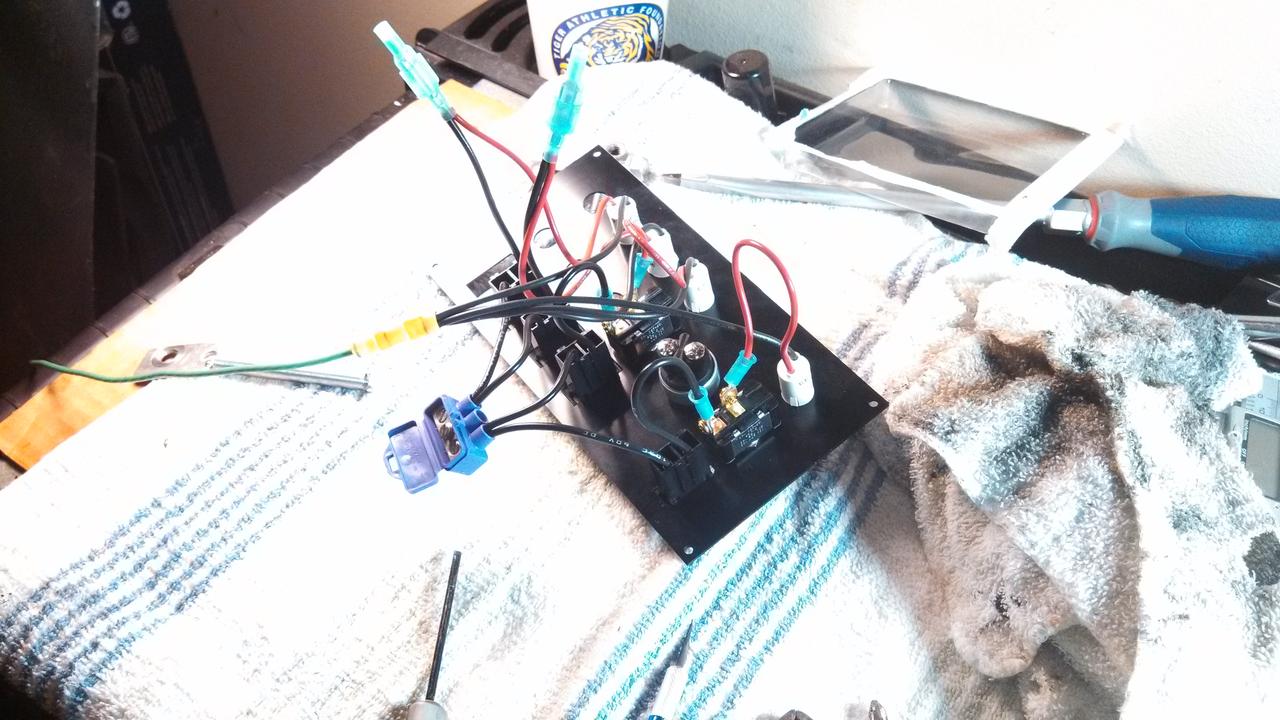
Fuse/switch panel came in. Wired up and ready to install once I make a faceplate to mount it on.

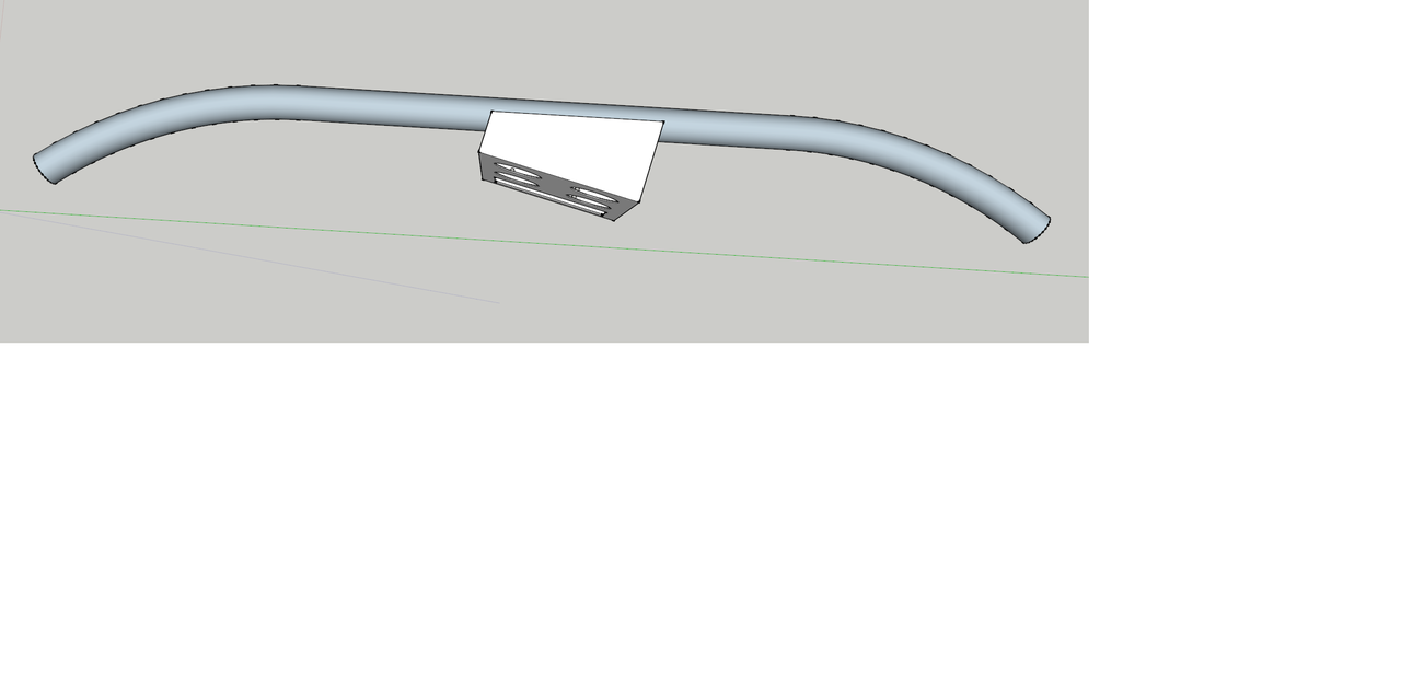
As of right now I have plans of adding a support to the roll cage across the top of the steering column and attaching the top of a panel to that and the bottom to the bolt holes right in front of the shifter. I'd like it to angle towards the driver. I made a quick model, nothing is to scale or exact.
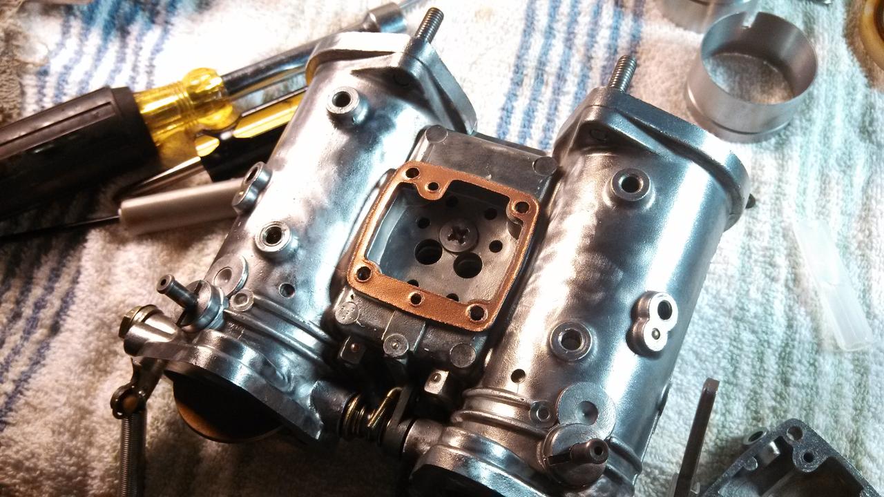
I used copper gasket spray on all the new gaskets and I went ahead and used the entire kit this time, replacing everything that came with the kit.
Yes, I put the diaphragm spring in. I just snapped the pic before I did.
Once the accelerator pump was rebuilt I made sure the diaphragm was pumping. Getting squirts of air through the pump nozzle!
The o-rings for the pump nozzle screw were worn to ****. They came out shaped like a countersink screw head instead of round. All the other o-rings looked in good shape but slightly hardened and deflated. They probably could have been re-used but I have more from the last kit I didn't use if I need them.
Filled two holes that are "closed" by the venturi. There is a very small crack around the venturies when they seat inside the carb as they go in there quite easily. It probably is barely enough to let a tiny amount of air in, if any, but I filled them with RTV anyways.
Fuse/switch panel came in. Wired up and ready to install once I make a faceplate to mount it on.
As of right now I have plans of adding a support to the roll cage across the top of the steering column and attaching the top of a panel to that and the bottom to the bolt holes right in front of the shifter. I'd like it to angle towards the driver. I made a quick model, nothing is to scale or exact.
Last edited by Shrimp; Jul 3, 2013 at 10:46 PM.
Thread Starter
Full Member
Joined: Apr 2012
Posts: 201
Likes: 0
From: Louisiana
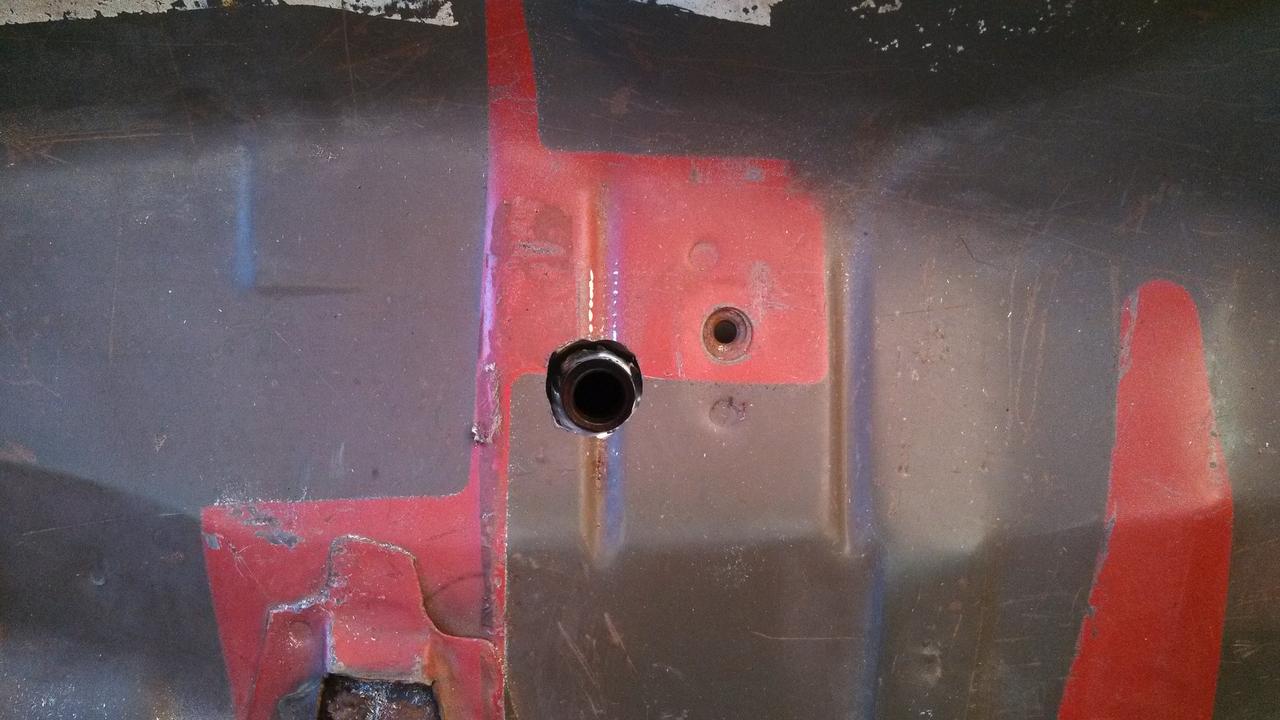
Bung welded on exhaust.
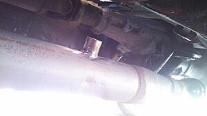
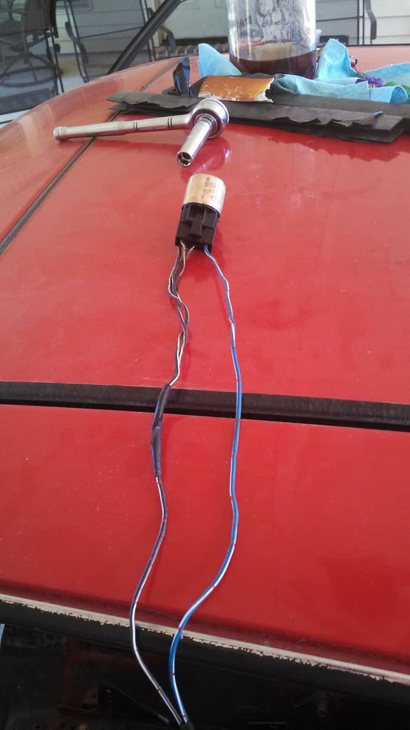
Hole cut to get sensor in/out for calibrating/routing cable. Going to put a rubber grommet here to prevent wear from rubbing, plus that edge is sharp.
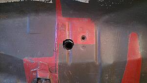
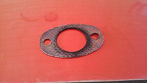
I need a new one of these. Going to research if I can maybe cut one out of some thin soft aluminum and spray it with some type of sealant.

Hole cut to get sensor in/out for calibrating/routing cable. Going to put a rubber grommet here to prevent wear from rubbing, plus that edge is sharp.
I need a new one of these. Going to research if I can maybe cut one out of some thin soft aluminum and spray it with some type of sealant.
