
82 GSL Build


Thread Starter
Full Member
Joined: May 2016
Posts: 226
Likes: 0
From: Denver
Ah thanks MIke, I had the sequence all backwards! I've been super busy getting my "new" daily in driving shape, so I haven't touched the seven, other than to find out the Cigar lighter, clock, and Alternator (.1 amp drain!)had combined to kill my new battery...
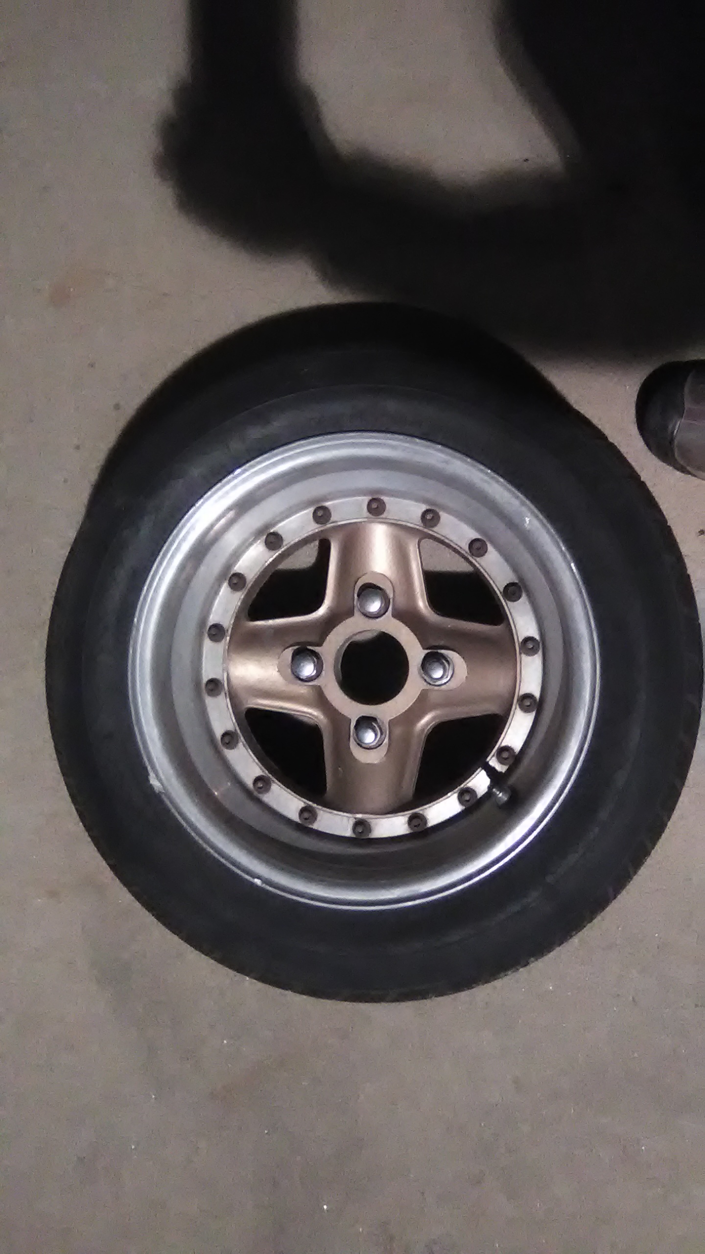
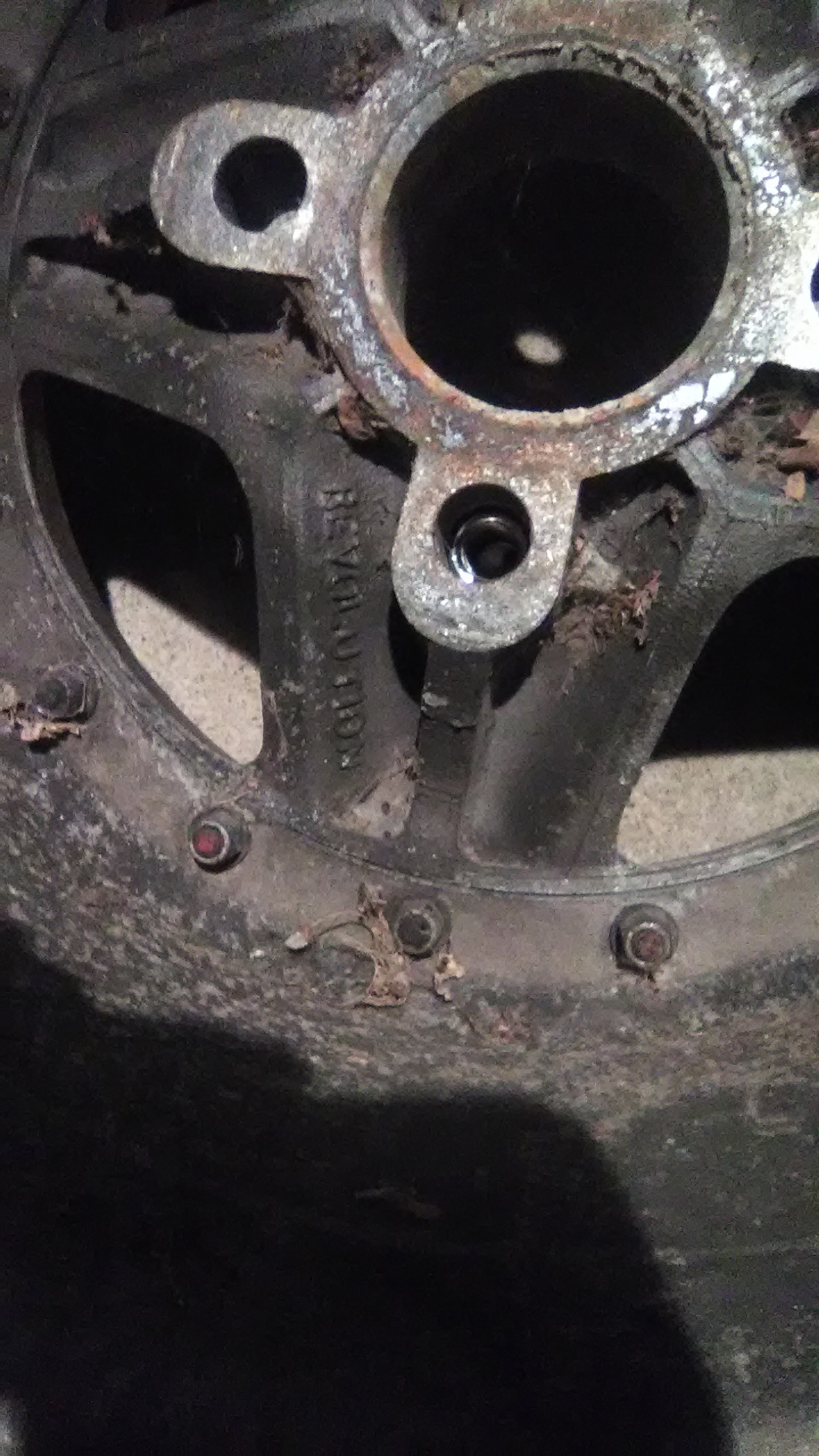
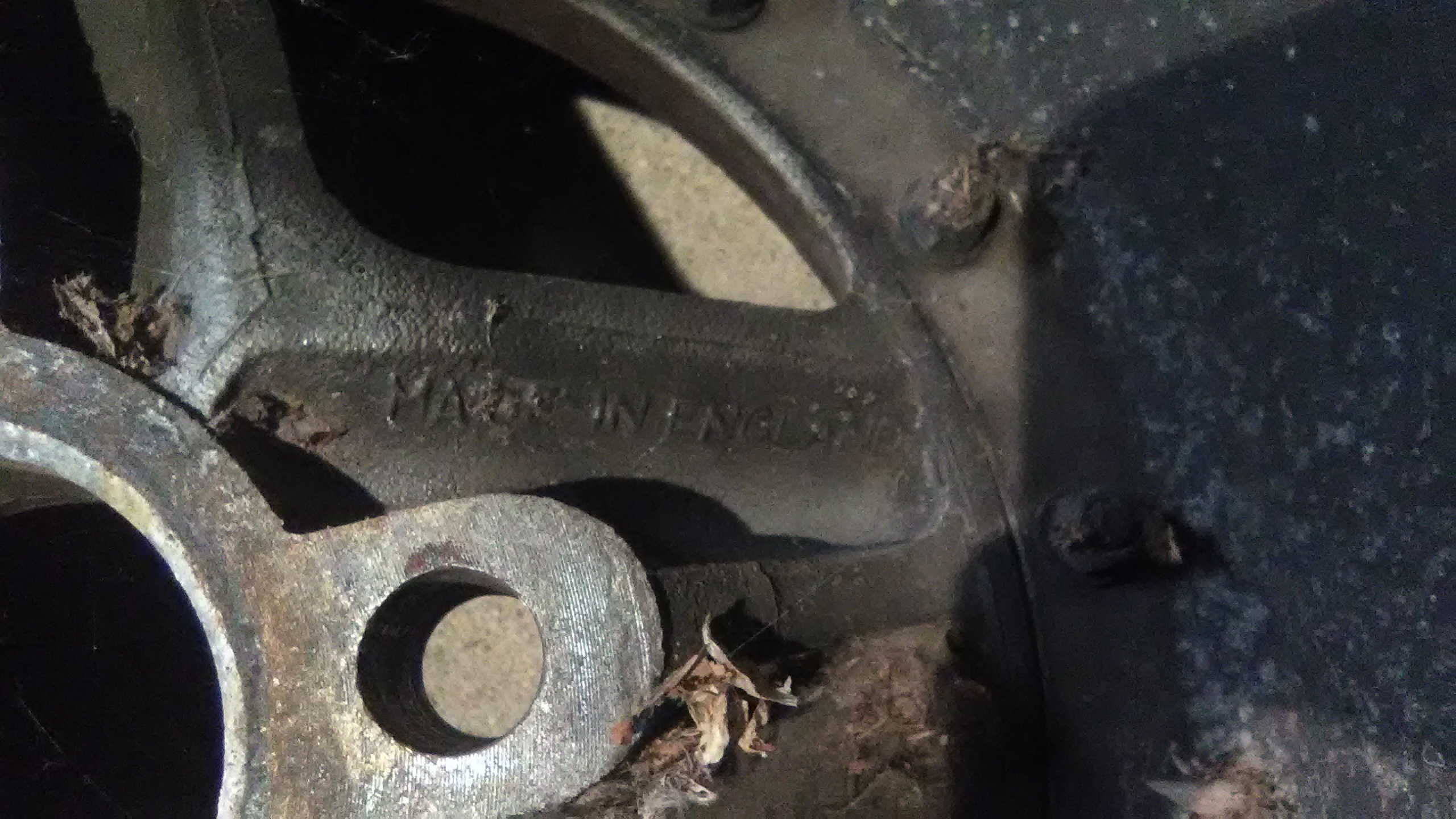
Hey I found these today when I went to pick up some tail lights and lenses from a guy parting out an RX7, what am I looking at? All 4 have damaged lips somehow, but they're super wide with 215 tires on only 13 inch diameter wheels on the 110 mm pattern. If it's not super clear they say 'Made in England' and Revolution on them, but no other markings. I wonder if they could be repaired?
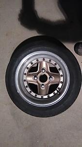
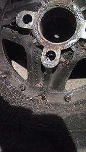
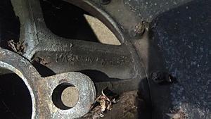
Hey I found these today when I went to pick up some tail lights and lenses from a guy parting out an RX7, what am I looking at? All 4 have damaged lips somehow, but they're super wide with 215 tires on only 13 inch diameter wheels on the 110 mm pattern. If it's not super clear they say 'Made in England' and Revolution on them, but no other markings. I wonder if they could be repaired?
Thread Starter
Full Member
Joined: May 2016
Posts: 226
Likes: 0
From: Denver
I decided to take the FB out for a trip around the block to do a shakedown. And it stalled, immediately and wouldn't restart. I could start it easily and restart it easily when it was on my up sloped driveway, but as soon as the car was nose down in the street (Our streets are very high in the centers) the car dies. I'm thinking float height maybe?
So I build a float sight, i.e. a clear piece of nylon tubing stuck on a bleeder valve threaded into the bowl drain of the Empi. I measure 35mm between the top of the fuel ( with pump running) and the airhorn gasket. I'm not sure what the correct height is supposed to be though and get all sorts of conflicting answers. My plugs, with only 9 miles on them are black! So I'm obviously rich. Will install Wideband O2 next weekend too.
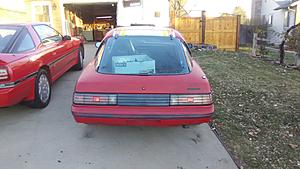
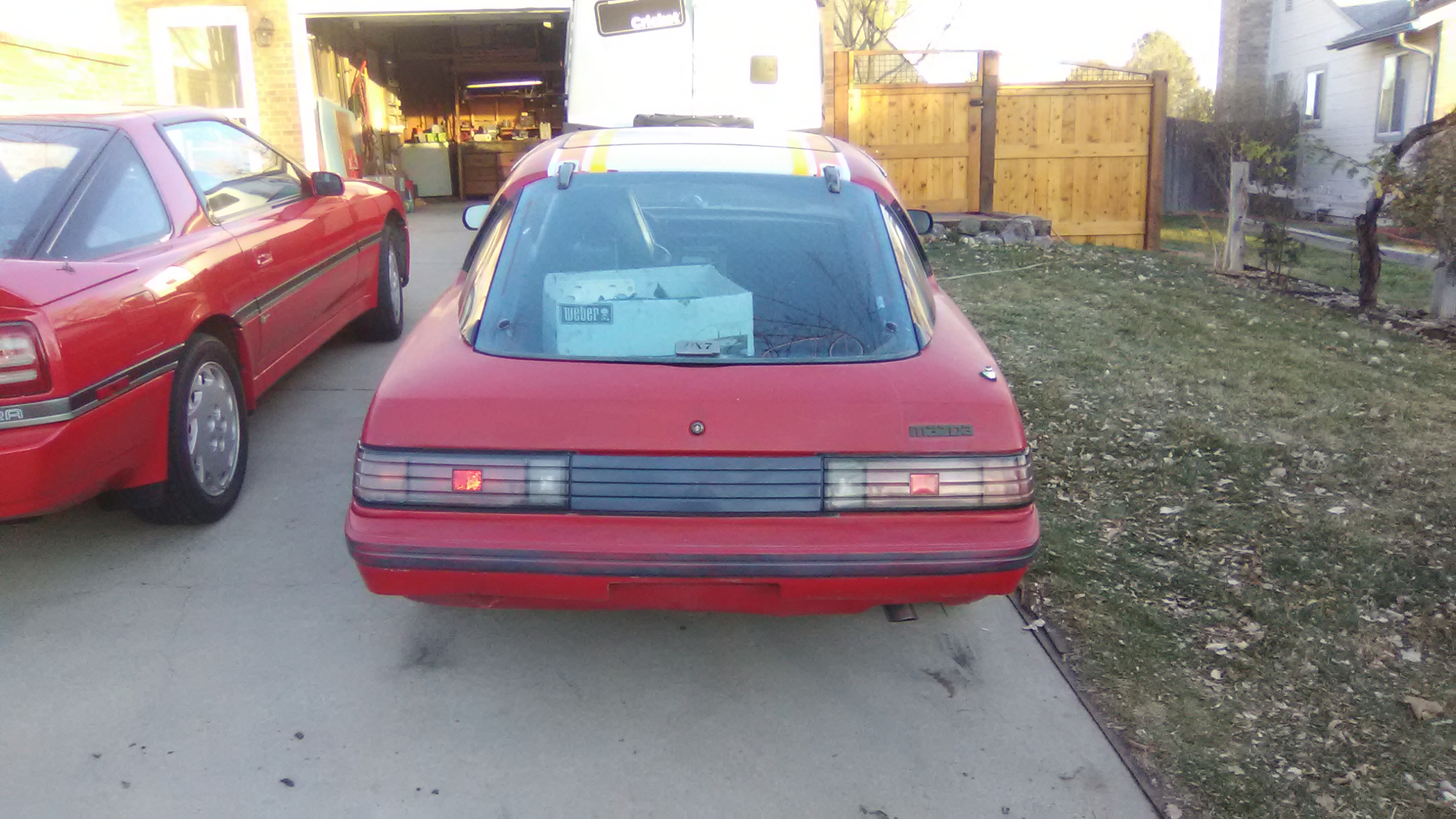
On the plus side I got the new Tailights and lenses installed and the hatch struts, no more banged head!
So I build a float sight, i.e. a clear piece of nylon tubing stuck on a bleeder valve threaded into the bowl drain of the Empi. I measure 35mm between the top of the fuel ( with pump running) and the airhorn gasket. I'm not sure what the correct height is supposed to be though and get all sorts of conflicting answers. My plugs, with only 9 miles on them are black! So I'm obviously rich. Will install Wideband O2 next weekend too.
On the plus side I got the new Tailights and lenses installed and the hatch struts, no more banged head!
Thread Starter
Full Member
Joined: May 2016
Posts: 226
Likes: 0
From: Denver
So much happy! I installed my new AEM wideband and I can finally see what's up with the carb. Turns out I had been adding a little oil, when starting the FB, as I was totally paranoid about starting it and getting proper lubrication. Well I fouled the plugs doing that, so a few seconds with a wire wheel and the car starts and runs fine. At cold idle I'm sitting around 14-1 afr. Under load/acceleration it drops to 11/10-1. Cruise with no load is near 15. So pretty average/reasonable numbers! I'll have some pics of the install later. It took a while but was not terrible the hardest part was disassembling the center console thing and finding power sources (used the old cassette player for Oil gauge light and AEM power source). Brakes are still shakey, but will have to fix those tomorrow!


Thread Starter
Full Member
Joined: May 2016
Posts: 226
Likes: 0
From: Denver
It's been a while! With the cold weather and holidays, the RX7 took a back seat. But no longer! I've finished the trailing ignition, essentially the same components as the primary, just routed through the dizzy cap instead of direct fire.
I went ahead and replaced every external bulb on the car, and found out I'm missing the guts for my passenger marker light, but overall everything lights up now!
Drivign the car is interesting, if youopen the throttle too quick it will die. there's also some odd hesitation right around 2k rpm, which I think is the transition point from idle to main circuit on IDA's. I do have the 3 progression hole variant of the carb, so I'll have to research more to smooth that out.
I also reinstalled the air pump, and the metal tube to the cat, so that I can pass the visual emissions. I failed both for not having the air pump, then again for not having an air filter on the airpump inlet! Want to make sure the air going in to the exhaust is clean after all...wtf eh? I also ordered the K&N filter assembly for a weber ida, so I'll finally have a proper air filter for the carb. Oh well going back next weekend to the emissions shop with the proper setup.
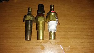
So I wanted to get my temp gauge working (I have no oil, temp or fuel working) and I bought a new temp sender, the one that goes under the oil filter pedestal. So it doesn't fit, then I bought an early one, with the spade connector, it doesn't fit either. They're simply too large to fit into the hole tapped into the iron. What's going on here? I read the early irons, which I think I have, had a different thread/sender diameter, so I bought the early one it's got the late style threads I think? Left is the old sender, center is one for an 80 supposedly, and right is the 82 sender.
I went ahead and replaced every external bulb on the car, and found out I'm missing the guts for my passenger marker light, but overall everything lights up now!
Drivign the car is interesting, if youopen the throttle too quick it will die. there's also some odd hesitation right around 2k rpm, which I think is the transition point from idle to main circuit on IDA's. I do have the 3 progression hole variant of the carb, so I'll have to research more to smooth that out.
I also reinstalled the air pump, and the metal tube to the cat, so that I can pass the visual emissions. I failed both for not having the air pump, then again for not having an air filter on the airpump inlet! Want to make sure the air going in to the exhaust is clean after all...wtf eh? I also ordered the K&N filter assembly for a weber ida, so I'll finally have a proper air filter for the carb. Oh well going back next weekend to the emissions shop with the proper setup.
So I wanted to get my temp gauge working (I have no oil, temp or fuel working) and I bought a new temp sender, the one that goes under the oil filter pedestal. So it doesn't fit, then I bought an early one, with the spade connector, it doesn't fit either. They're simply too large to fit into the hole tapped into the iron. What's going on here? I read the early irons, which I think I have, had a different thread/sender diameter, so I bought the early one it's got the late style threads I think? Left is the old sender, center is one for an 80 supposedly, and right is the 82 sender.

So I wanted to get my temp gauge working (I have no oil, temp or fuel working) and I bought a new temp sender, the one that goes under the oil filter pedestal. So it doesn't fit, then I bought an early one, with the spade connector, it doesn't fit either. They're simply too large to fit into the hole tapped into the iron. What's going on here? I read the early irons, which I think I have, had a different thread/sender diameter, so I bought the early one it's got the late style threads I think? Left is the old sender, center is one for an 80 supposedly, and right is the 82 sender.
Attachment 733813
Attachment 733813
Part number I used: 18-51X0-G607
"Note: A few years ago MAZDA changed the thread on the water temp sender in the rear side housing from the straight thread that they had used forever, to a metric pipe thread. All NEW replacement rear side housings have the new thread. It is impossible to know which you have with out looking at it. Most cars still use the straight thread. However, if the engine has been replaced with a FACTORY rebuilt, there is a small chance you have the pipe thread. To identify the thread on your sender, look to see how it seals- the straight thread units use an aluminum crush washer and the pipe thread units do not.The new sender will not read correctly in pre-80 cars"
Last edited by KansasCityREPU; Jan 7, 2018 at 04:37 PM.
Thread Starter
Full Member
Joined: May 2016
Posts: 226
Likes: 0
From: Denver
Triumph and Tragedy
I got my new air filter assembly figured out
Attachment 734198
Only tricky part is the tiny bit of trimming of the gasket and actually fitting the venturi hold downs in to that tiny space. It's part number 56-1210 at K&N.
The other part was the omp lines. I found out that an Accord 88-2000, has the M10x1.25 thread that RB uses on the manifold.So all I did was cut off the non-threaded part, and then I have an elusive M10x1.25 nipple!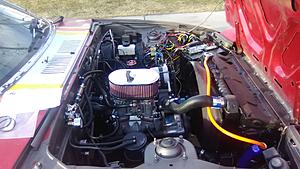
The Accord nipples will need 3/16th line to fit over them so it's a tiny bit big for the OMP barbs, but with some crimps should work fine.
And on to the tragedy part.
After getting all that set up, I decided to take the 7 around the block, to test stuff. Oh and to hear the glorious noises, you know typical rotary stuff...So I pull over about 1/2 mile from the house, because I think I smell a bit of hot brake smell, and so I shut the car off, and adjust my e-brake. I go to start the car back up, and nothing, it cranks, backfires, but no start. OK I flooded it...So I pull out the plugs, spin the motor over, and de-flood. Clean the plugs off (They're oily smelling), and try restarting it. No go. I pull the plugs again, lay em on the fender, and check for spark, yep they're sparking!. I check for fuel pressure, yep 2.5 lbs, good to go. No start. I double checked the discreete grounds for each module, as one had come loose earlier, they seem good. I end up towing the car back to the house with my dad's truck. So I'll get out on it tomorrow, and see wtf is going on.
I got my new air filter assembly figured out
Attachment 734198
Only tricky part is the tiny bit of trimming of the gasket and actually fitting the venturi hold downs in to that tiny space. It's part number 56-1210 at K&N.
The other part was the omp lines. I found out that an Accord 88-2000, has the M10x1.25 thread that RB uses on the manifold.So all I did was cut off the non-threaded part, and then I have an elusive M10x1.25 nipple!

The Accord nipples will need 3/16th line to fit over them so it's a tiny bit big for the OMP barbs, but with some crimps should work fine.
And on to the tragedy part.
After getting all that set up, I decided to take the 7 around the block, to test stuff. Oh and to hear the glorious noises, you know typical rotary stuff...So I pull over about 1/2 mile from the house, because I think I smell a bit of hot brake smell, and so I shut the car off, and adjust my e-brake. I go to start the car back up, and nothing, it cranks, backfires, but no start. OK I flooded it...So I pull out the plugs, spin the motor over, and de-flood. Clean the plugs off (They're oily smelling), and try restarting it. No go. I pull the plugs again, lay em on the fender, and check for spark, yep they're sparking!. I check for fuel pressure, yep 2.5 lbs, good to go. No start. I double checked the discreete grounds for each module, as one had come loose earlier, they seem good. I end up towing the car back to the house with my dad's truck. So I'll get out on it tomorrow, and see wtf is going on.
Thread Starter
Full Member
Joined: May 2016
Posts: 226
Likes: 0
From: Denver
Crisis averted! Turns out it was the same damn grounds on the GM ignitors. Now everything is locktited, and the car's running better. There's still a small miss at idle and I'm not getting much leaner than 13.5 at idle, but I'm likely needing to change the idle jets and air correctors. Oh and the emulsion tube, as there's a flat spot at 2k under load. It's an F7 I think.

Thread Starter
Full Member
Joined: May 2016
Posts: 226
Likes: 0
From: Denver
Ah sorry totally forgot to take pictures. But really it's super simple. I just got some Stainess picture hanging wire from Home Depot, and some crimps. Made a loop through the OMP lever and then with just a bit of tension, put it to the throttle lever on the Weber. You might want to use a 90 or a 45 fitting from a bike brake line to route the cable. I didn't need one, but it's nice to have if you ant to look professional.
So Here I was all excited to take the FB to emissions, finally. Got my fancy new K&N air filter, new O2 pump filter, and jury-rigged O2 feed pipe. And it's dying on me, doesn't want to start. Come to find out my brand new alternator, with all of 20 miles on it is shot. I measure 12.5 vvolts at the battery termials with the car running, or of. Took the alt to a shop for testing and they confirmed it was dead. On the upside I'm upgrading to a S5 turbo alt. So 6-8 days form now I'll have a running car again. Damn.
So Here I was all excited to take the FB to emissions, finally. Got my fancy new K&N air filter, new O2 pump filter, and jury-rigged O2 feed pipe. And it's dying on me, doesn't want to start. Come to find out my brand new alternator, with all of 20 miles on it is shot. I measure 12.5 vvolts at the battery termials with the car running, or of. Took the alt to a shop for testing and they confirmed it was dead. On the upside I'm upgrading to a S5 turbo alt. So 6-8 days form now I'll have a running car again. Damn.
Thread Starter
Full Member
Joined: May 2016
Posts: 226
Likes: 0
From: Denver
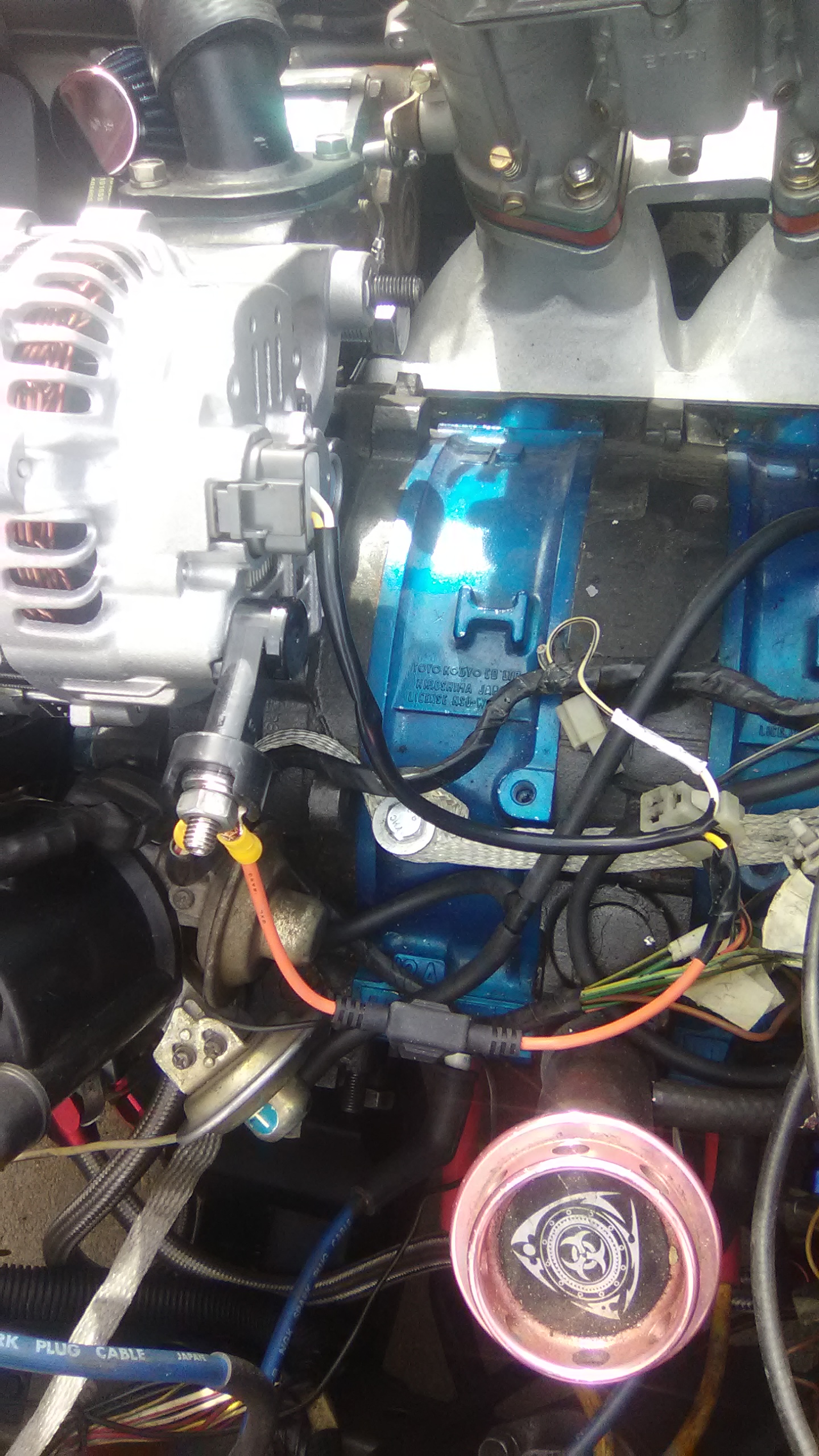
New FC alternator installed! Super easy really. Some washers for spacers for the lower mount and a 5 amp fuse for the sensor wire.

So I'm now finally getting voltage to the battery, yay!
And the car is still a bitch to start! It floods super easy it seems. It's like it has to spin really fast to start at all. I think my main jets are conservative, running 2.5 psi fuel pressure. Right now I'm running 37mm venturis, 135 main fuel, 120 air corrector jets, and .65 idles. I'm seeing a fluctuating 12.5-13.5 afr at idle, which is really confusing. Vacuum leak? The idle scres are out 2 turns which I think means they're too small idle mix, but my O2 says I'm running rich. Maybe bigger idle jets with bigger air correctors? I'm thinking if I understand the IDA correctly, that the idle screws only control volume, not afr mixture, which would explain a lot. Help would be appreciated lol.
Hard to tell from the photos but you shouldn't wire the post directly to the sense input on the alternator. The sense input should connect to the fuse box or ignition. The length of wire is key, as voltage drops as it comes off the post, goes to the fuse box, and comes back to the alternator.
Thread Starter
Full Member
Joined: May 2016
Posts: 226
Likes: 0
From: Denver
Hmm, I was thinking the same thing, that it was wrong to put the alt sense wire to that output post! But lots of diagrams showed it that way. I'll move it to the main fuse block, where the W/R wire connects. Thanks for the tip
So I figured out the hard starting, my timing was way too advanced. With the Vacuum disconnected and plugged, I set the leading to the first mark viewed clockwise when the engine is running. Now it starts up real easily! My trailing doesn't seem to be cooperating though, as I can't get the red mar (the left one) to line up no matter where I push the trailing slide thingy. So right now It's sitting at the same location as the leading mark. Car seems happy. Although I notied there's timing fluctuation of 1-3 degrees either way when running, I suspect the dizzy bushings. Anyone know if these are rebuildable?
Still need to get some emulsion tubes to conquer the 2k rpm stumble. I read the F3's work very well?
Yes, there are dozens of diagrams on the internet that suggest connecting the two posts together. They are wrong and no factory wiring schematic will show that. The car will run and the system will eventually recharge the battery, but you'll also end up running a lower voltage than intended and the regulator will wear out prematurely, and it will take longer for your battery to charge.
As far as the timing goes, are you sure leading and trailing are connected properly and not swapped?
As far as the timing goes, are you sure leading and trailing are connected properly and not swapped?
Thread Starter
Full Member
Joined: May 2016
Posts: 226
Likes: 0
From: Denver
I actually found the info here (RX7club), from what seemed to be reputable posters, lots of counts and long experience I think. Anyway, it's neither here nor there, I'll change it.
Yeah very certain they're not swapped. It's been converted to DLIDFI. Now I may change the polarity on the feed to the Ignitor I'm using, see if that brings it into spec, as I've read having the + and - swapped will cause 25 degrees out or so. I was thinking that may be the problem, but it was dark/cold out, will check tomorrow.
Yeah very certain they're not swapped. It's been converted to DLIDFI. Now I may change the polarity on the feed to the Ignitor I'm using, see if that brings it into spec, as I've read having the + and - swapped will cause 25 degrees out or so. I was thinking that may be the problem, but it was dark/cold out, will check tomorrow.

ancient wizard...
Joined: Sep 2014
Posts: 2,335
Likes: 262
From: Maryland
First off,that's an FD alternator,not an FC. An FC alternator would have the same receptacle on back of housing your original did and your original FB field plug would have plugged right in... On the connector/pigtail on back of your FD alternator,the yellow wire is the exciter terminal of voltage regulator and should be connected to white/black? wire that was in original FB Alt plug. The white wire in connector on back of FD alternator should be connected to other wire from same FB connector and should be black/white,this is for battery warning light in bottom dash light display. If not hooked up this way,all your warning lights on dash will not work. Very likely you'll need to wire in a diode on the white/black wire as on shutdown the regulator will stay energized and drain battery over course of a couple days. Last,you need to address the alternator output wiring,one look at output stud on your new alternator tells you it is meant to carry more amperage. You need to upgrade the alt output wire gauge,stock FD alt =90 amps. Recommend you make up a larger gauge fused output wire and run it back to and connect to positive battery terminal. If 90 amp alt,use 100 amp fuse. Reason for this,if the battery is ever low (Left lights on/had to be jumped),and the (more powerful) alternator is charging at a good rate,it can easily overheat the main fuse link on your car and melt it as it's total amp rating is only about 60 amps. Also without upgrading your alternator output wiring,you'll never reap the full benefits of the larger alternator. Couple pics of FD alt install on my SE,this alt. is 130+ amps. I did a 2nd gen fusebox upgrade and upped main fuse in fusebox to 150 amps with thicker gauge wiring to match. Fuseholders i describe can be bought at Napa,can post pic of one of them and fuses that go in it so you can see what it looks like.
Last edited by GSLSEforme; Jan 31, 2018 at 02:12 PM. Reason: Realized i gave incorrect wire colors
Thread Starter
Full Member
Joined: May 2016
Posts: 226
Likes: 0
From: Denver
Hmm, surprised it's an FD, as it's supposed to go into a 90 Turbo II, but they may have given me the wrong one. I thought only the S4 had the same connector as the FB, but hey I could be very wrong. Now what sort of diode would I need to put inline, in terms of amperage rating? I'll go out and check everything out tomorrow, it's too dang cold out tonight, and the car's leaking gas from somewhere...It never ends does it? But hey I guess that's part of the charm of these cars. Thanks again for all the good info, and that install looks great.
Yeah, but when you get it all straitened out its the best feeling ever.
ancient wizard...
Joined: Sep 2014
Posts: 2,335
Likes: 262
From: Maryland
Diode, 3 amp more than enough,1 amp would suffice. I like to use the larger one strictly for its hardier construction for use inline of harness,usually heat shrink it into harness to give it more stability. They don't tolerate heat well,use heat sink while soldering. Orient the banded end toward alternator,install in exciter wire to regulator(yellow wire in your Alternator connector-white/black wire in original Alternator harness). No need for inline fuse in this circuit.You can see the heatshrinked diode lump in my harness in pic of alternator,right behind insulating boot on output stud of alternator. Pics of Hi-Amp fuseholder and fuse next to it in pics. What is amp rating of your replacement alternator?
ancient wizard...
Joined: Sep 2014
Posts: 2,335
Likes: 262
From: Maryland
If you've upgraded your alternator more than 20 amps higher than oe you'd want to run a wire of identical size from battery with an inline fuseholder rated about 10 amps more than output of alternator for same reason recommended to op. Attach the output wire from alternator and the power wire for main fuselink to the fused side of fuseholder. Allows full complement of alternator output to get to battery without resistance of now undersized main fuselink supply wire. Makes for brighter headlights,running lights,more air from blower motor,p/windows down/up faster. Also best place to take power from for added accessories(electric cooling fan) without cluttering/compromising connections at battery.
Last edited by GSLSEforme; Feb 1, 2018 at 06:01 PM.
In my case I was wiring a REPU, with a rear mounted battery. I used the original 50a main fuse along with ammeter shunt between battery and new fuse block. That wire is 8ga, thicker strand, because the connections wouldn't allow for larger gauge. Then I have the 4ga off the alternator that also goes straight to fuse box with a 150a inline fuse. Everything in the truck gets power direct from this fuse box except for starter motor. The sense input on the alternator is connected to ignition switch, which gets power from the fuse box, so it's sensing a typical length of 16ga wire that is fairly long. The ECU reports a steady 13.7v. The ammeter (which works!) shows how the current across that 8ga battery cable fluctuates. It flickers a little driving around but not much. It'll show about +25a charging a dead battery (left the lights on once). It flickers to -5a when the electric fan kicks on then quickly goes back to 0. Same for lights and other accessories. I've also upgrade ground wires using 4ga wire. Battery to chassis, chassis to cab, cab to engine block, engine block to chassis.
ancient wizard...
Joined: Sep 2014
Posts: 2,335
Likes: 262
From: Maryland
In my case I was wiring a REPU, with a rear mounted battery. I used the original 50a main fuse along with ammeter shunt between battery and new fuse block. That wire is 8ga, thicker strand, because the connections wouldn't allow for larger gauge. Then I have the 4ga off the alternator that also goes straight to fuse box with a 150a inline fuse. Everything in the truck gets power direct from this fuse box except for starter motor. The sense input on the alternator is connected to ignition switch, which gets power from the fuse box, so it's sensing a typical length of 16ga wire that is fairly long. The ECU reports a steady 13.7v. The ammeter (which works!) shows how the current across that 8ga battery cable fluctuates. It flickers a little driving around but not much. It'll show about +25a charging a dead battery (left the lights on once). It flickers to -5a when the electric fan kicks on then quickly goes back to 0. Same for lights and other accessories. I've also upgrade ground wires using 4ga wire. Battery to chassis, chassis to cab, cab to engine block, engine block to chassis.