
'80 with 6-port engine


Thread Starter
Full Member
Joined: May 2013
Posts: 62
Likes: 9
From: Florence, Italy
I'm working again on the car, and this time I'm doing the impossible:
after going through lots of problems with my marine holley 4160 I'm in the process of converting the engine to EFI. Ironically this engine has gone full-circle, coming from a GSL-SE, converted to carb, and then re-converted to EFI, and all this on a car born with a 12A in it.
The problems I had with the holley were mainly maintenance issues caused by stagnating fuel: impurities, corrosion, lots of cleaning.. then the electric choke failing, then vacuum issues.. and here you can't find holley spares at the store down the street, I had to order from USA every time.
So, after some search I concluded that I was going to keep the holley intake manifold, and use a self-tuning carb-replacement EFI kit, and I choose the Fitech kit simply because it was the simplest one, without ignition control and without huge injectors or drag-racing features. I saw someone on this forum talking about testing it but he never got the kit, so I guess it's my duty to inform the community if the conversion is any good, and what is the process of doing it.
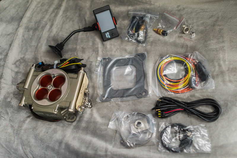
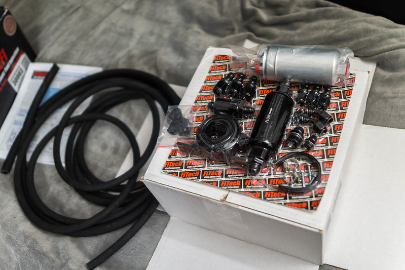
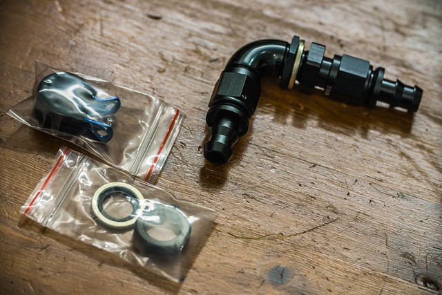
I wrote to Fitech and explained the situation, they suggested to speak with their UK distributor, and I did. After a week or so I managed to have everything at my door, in Italy. I bought also their fuel line replacement kit, because I don't have the time to find all the right parts:
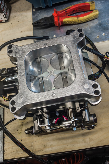
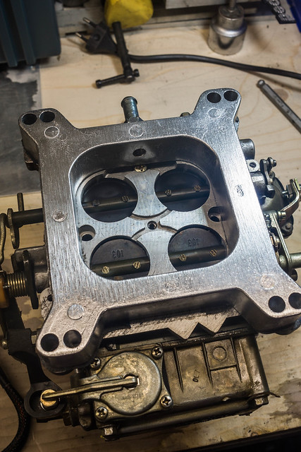
First thing, I removed the Holley carb and compared the two units:
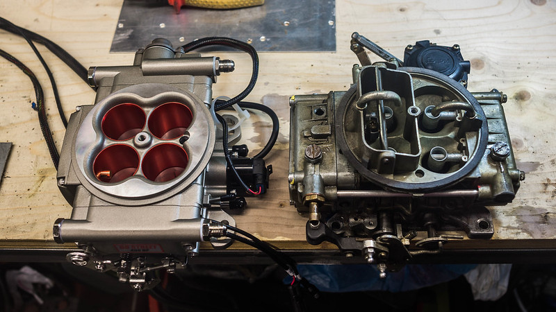
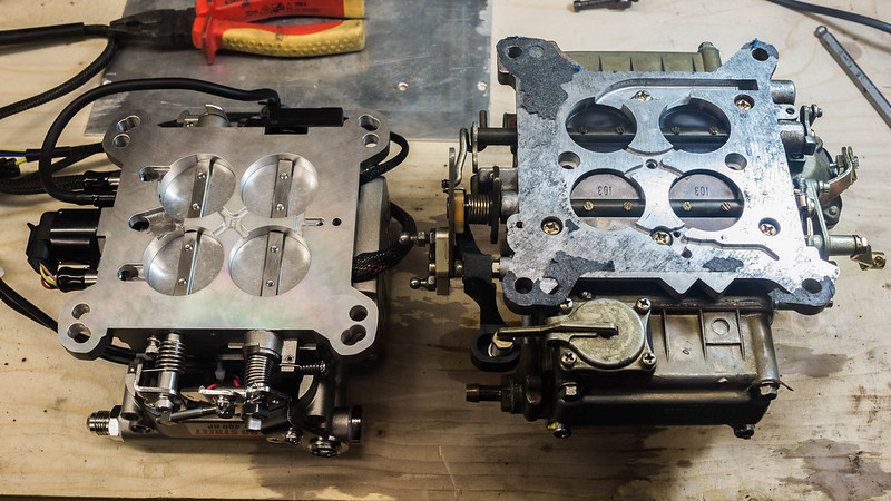
as you can see, the Fitech has a bigger bore: 4 x 42mm compared to 4 x 36mm
At the time of writing this post I'm already several days into the project but I didn't have the time to download all the pictures from the camera; I can already say that the process is not complicated so far: the only pain in the a** is the fuel tank and fuel lines coming from and to it.
It seems that I will have to take out the tank and enlarge the outlet to the pump specs, otherwise (they say) the pump will starve and fail.
Do you have any other idea? low pressure pump, surge tank, and then EFI pump? I don't like it very much.. too much noise and too small space to fit all the components..maybe trying an in-tank pump? but it's a huge work...
Do you think I can try to mount it with the stock tank, hoping that a 160-180hp engine will not starve a 400hp-rated EFI kit?
Why does it need a huge 1/2" hose to feed the pump? I never seen such a hose on modern cars...
Anyway in my next post I will show the mounting of the sensors and the research I had to do to find a suitable engine temperature sensor.
If you want more detailed pictures you can find them on my Flickr set: https://www.flickr.com/photos/dariom...57635186022443
after going through lots of problems with my marine holley 4160 I'm in the process of converting the engine to EFI. Ironically this engine has gone full-circle, coming from a GSL-SE, converted to carb, and then re-converted to EFI, and all this on a car born with a 12A in it.
The problems I had with the holley were mainly maintenance issues caused by stagnating fuel: impurities, corrosion, lots of cleaning.. then the electric choke failing, then vacuum issues.. and here you can't find holley spares at the store down the street, I had to order from USA every time.
So, after some search I concluded that I was going to keep the holley intake manifold, and use a self-tuning carb-replacement EFI kit, and I choose the Fitech kit simply because it was the simplest one, without ignition control and without huge injectors or drag-racing features. I saw someone on this forum talking about testing it but he never got the kit, so I guess it's my duty to inform the community if the conversion is any good, and what is the process of doing it.
I wrote to Fitech and explained the situation, they suggested to speak with their UK distributor, and I did. After a week or so I managed to have everything at my door, in Italy. I bought also their fuel line replacement kit, because I don't have the time to find all the right parts:
First thing, I removed the Holley carb and compared the two units:
as you can see, the Fitech has a bigger bore: 4 x 42mm compared to 4 x 36mm
At the time of writing this post I'm already several days into the project but I didn't have the time to download all the pictures from the camera; I can already say that the process is not complicated so far: the only pain in the a** is the fuel tank and fuel lines coming from and to it.
It seems that I will have to take out the tank and enlarge the outlet to the pump specs, otherwise (they say) the pump will starve and fail.
Do you have any other idea? low pressure pump, surge tank, and then EFI pump? I don't like it very much.. too much noise and too small space to fit all the components..maybe trying an in-tank pump? but it's a huge work...
Do you think I can try to mount it with the stock tank, hoping that a 160-180hp engine will not starve a 400hp-rated EFI kit?
Why does it need a huge 1/2" hose to feed the pump? I never seen such a hose on modern cars...
Anyway in my next post I will show the mounting of the sensors and the research I had to do to find a suitable engine temperature sensor.
If you want more detailed pictures you can find them on my Flickr set: https://www.flickr.com/photos/dariom...57635186022443
interested in seeing how this works out. been looking into these types of kits for some time now. there's a couple of the manufacturers of these kits also offer a surge tank. u would be able feed it with the stock pump.
Thread Starter
Full Member
Joined: May 2013
Posts: 62
Likes: 9
From: Florence, Italy
Today I found some time to do some photography so here is my update:
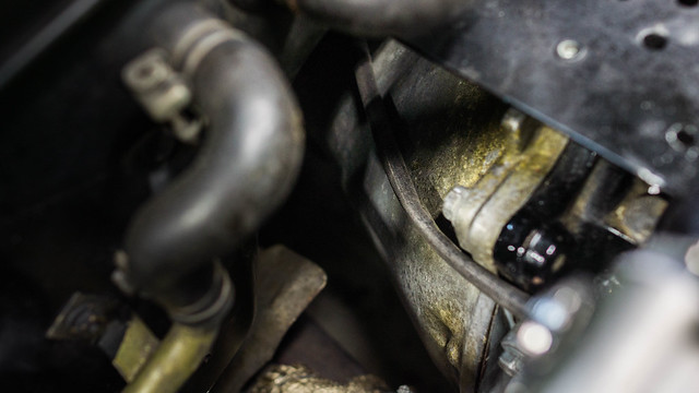
now I'm working on the fuel lines, and the sensors. I have the RB header with the O2 bung, and the previous owner closed the hole with some handmade plug, really badly made, and it damaged all the threads in the hole. the threads are M18 (18mm), 1,5mm pitch and it's not a common thread so finding the tap was difficult, but two days later I found one in the shop at work (I work in jewelry and fashion industry, so you can imagine my surprise, finding such a big and uncommon tap in the shop).
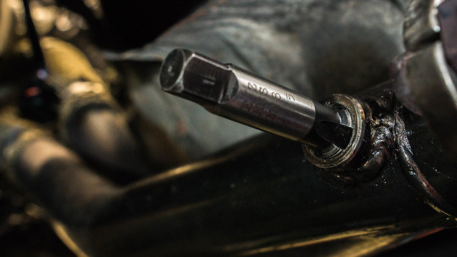
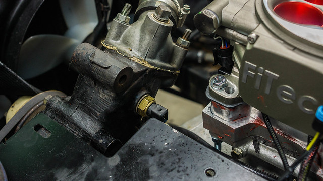
Then, I finally managed to screw the sensor in:
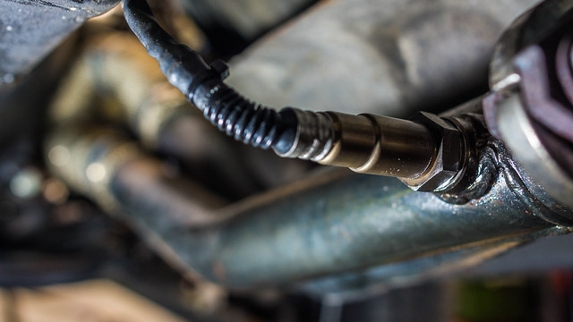
The included wire is a bit too short and the best way I found to connect it is to go around the gearbox from below and then above the flywheel. It's not the shortest way but it has some anchor points on gearbox and will not suffer from the heat of the manifold.
Now for the temperature sensor: that was actually a nightmare and I'm proud I solved it; the kit includes a GM style sensor, which of course doesn't have the correct thread pattern to screw into a japanese engine, so I began to search online and nothing... no one has wrote anything about it, then I had to go by exclusion: the threads are M16, 1,5 pitch (again not very common, even among sensors) and on a catalogue I found ONE that was the correct type (NTC), then of course no datasheet, so using a shop manual for a car that used that very sensor I found some data to use to see if it was similar to the GM one, and it was! 5volts and almost same resistance across all the temperatures
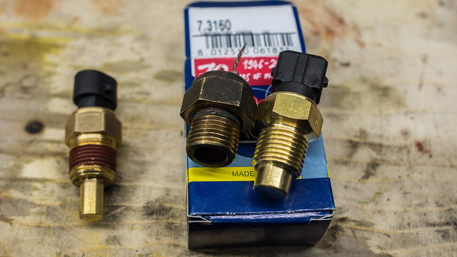
on the left the GM one, center Mazda, right the new one. if you need the code is on the box, and it's available from many companies (this one from Facet). It's used on Fiat and Alfa Romeo "JTD" motors.
And now for the bad news:
the kit comes with pump, filters, hoses and fittings, and they say to avoid hoses smaller than AN-08 for the pickup.
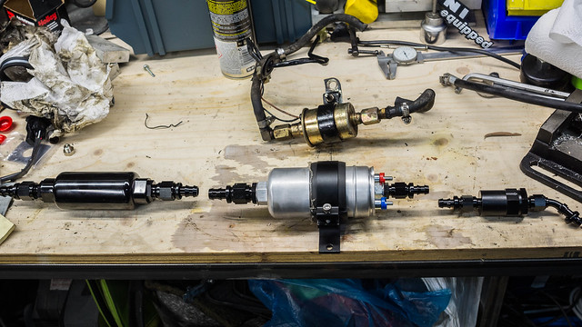
(above in the picture, the old pump)
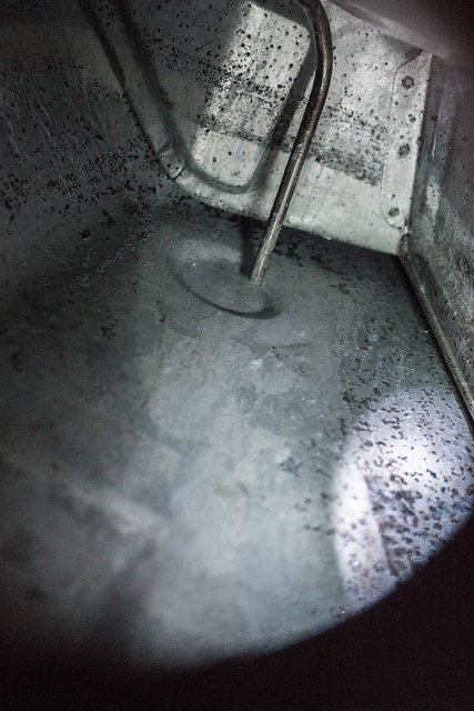
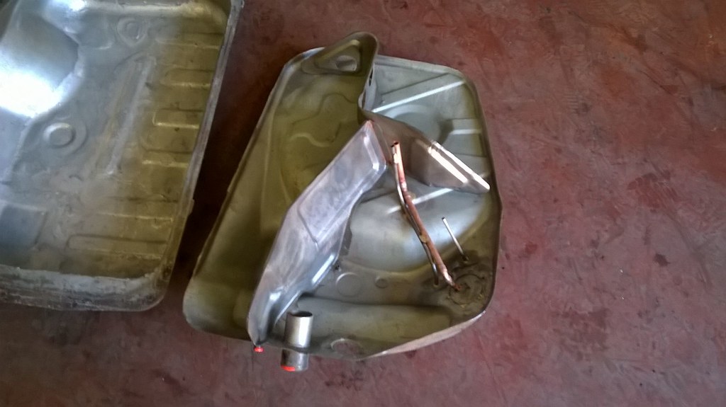
The bare minimum they say it's AN-06, and of course the Mazda one is even smaller (about 6mm inside), so I guess I have to make a bigger pickup for the tank. While I was taking off the hoses and hard-lines I noticed pieces of rust inside, so of course I was curious to see what was inside the tank, and as expected...
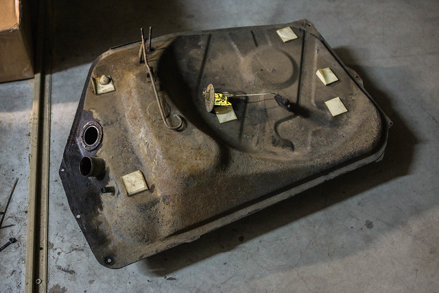
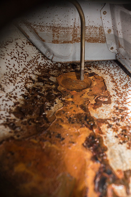
And this is after a quick pass with a rust converter I had in the garage:

Now I'm waiting for a proper tank sealing kit to arrive in the mail, and in the meantime I will try to find a bulkhead AN-08 fitting to put on my tank.
now I'm working on the fuel lines, and the sensors. I have the RB header with the O2 bung, and the previous owner closed the hole with some handmade plug, really badly made, and it damaged all the threads in the hole. the threads are M18 (18mm), 1,5mm pitch and it's not a common thread so finding the tap was difficult, but two days later I found one in the shop at work (I work in jewelry and fashion industry, so you can imagine my surprise, finding such a big and uncommon tap in the shop).
Then, I finally managed to screw the sensor in:
The included wire is a bit too short and the best way I found to connect it is to go around the gearbox from below and then above the flywheel. It's not the shortest way but it has some anchor points on gearbox and will not suffer from the heat of the manifold.
Now for the temperature sensor: that was actually a nightmare and I'm proud I solved it; the kit includes a GM style sensor, which of course doesn't have the correct thread pattern to screw into a japanese engine, so I began to search online and nothing... no one has wrote anything about it, then I had to go by exclusion: the threads are M16, 1,5 pitch (again not very common, even among sensors) and on a catalogue I found ONE that was the correct type (NTC), then of course no datasheet, so using a shop manual for a car that used that very sensor I found some data to use to see if it was similar to the GM one, and it was! 5volts and almost same resistance across all the temperatures
on the left the GM one, center Mazda, right the new one. if you need the code is on the box, and it's available from many companies (this one from Facet). It's used on Fiat and Alfa Romeo "JTD" motors.
And now for the bad news:
the kit comes with pump, filters, hoses and fittings, and they say to avoid hoses smaller than AN-08 for the pickup.
(above in the picture, the old pump)
The bare minimum they say it's AN-06, and of course the Mazda one is even smaller (about 6mm inside), so I guess I have to make a bigger pickup for the tank. While I was taking off the hoses and hard-lines I noticed pieces of rust inside, so of course I was curious to see what was inside the tank, and as expected...
And this is after a quick pass with a rust converter I had in the garage:
Now I'm waiting for a proper tank sealing kit to arrive in the mail, and in the meantime I will try to find a bulkhead AN-08 fitting to put on my tank.
Last edited by the thing; Nov 15, 2016 at 02:22 PM.
carb whisperer
Joined: Jan 2008
Posts: 1,485
Likes: 4
From: Greenfield, Ohio
Thread Starter
Full Member
Joined: May 2013
Posts: 62
Likes: 9
From: Florence, Italy
Haha, sorry for keeping you waiting but I had to change my job and then came the holydays, but in the next weeks I will resume working on the car! The good news is that in my new job I will work again in a machine shop instead of being all day in front of a computer screen, and I'll be able to make custom parts if I need them.

Thread Starter
Full Member
Joined: May 2013
Posts: 62
Likes: 9
From: Florence, Italy
I planned for months to have this week free from work, to dedicate entirely on working on the car, but I had other important stuff to do so this morning was the only time I had.
I wanted to make a post once I completely restored the tank but since it will take longer than expected I figured it's better if I do it now:
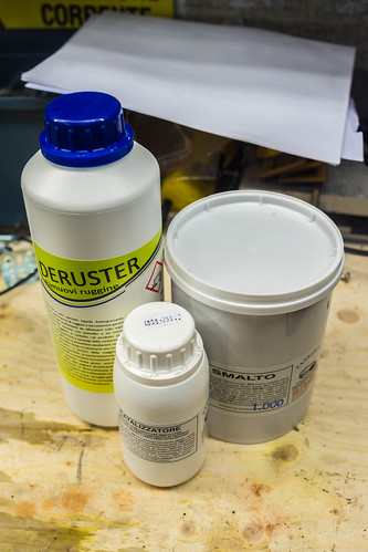
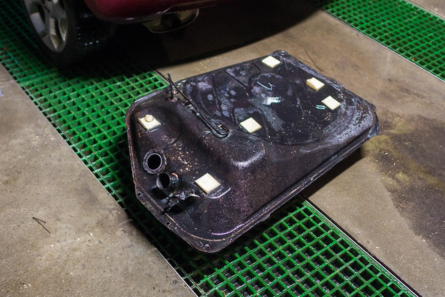
this is the tank sealing kit I bought. I proceeded to apply all the necessary steps: brush everything, put the solution, wait, rinse, repeat until the tank is like new, but having only few hours to spend on it each day meant that I couldn't dry the tank and immediately apply the epoxy paint.. at the end I had to plan every step to finish it in only one evening, and one of the step was to rinse completely the tank and the only place I knew to do so was the car wash, so at 10PM I put the tank in the car and went to the car wash:
then back to home, I put the tank on the heater to dry it, and using hairdryer, vacuum cleaner, etc. I managed to dry it, and at 1AM I applied the epoxy sealant.

(I can't find pictures of the sealed tank now)
then I had to wait for the epoxy to harden, and in the meantime this arrived:
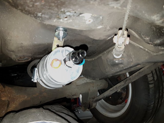
Also I finally found the space to put the pump and filter, without bulging under the car, and to do that I had to make brackets for them.
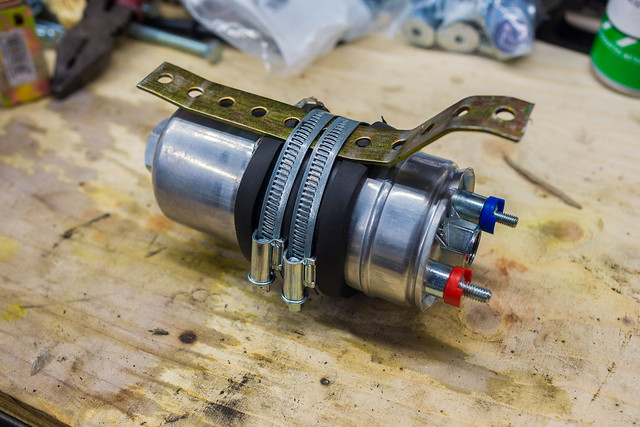
This is not final, but it's already very sturdy, despite the appearance.
It became clear that I had to modify few things to mount the new big hose in the tank, and I made a new port on the top to attach everything.
..then I had no more time because of my job, and only today I manage to return to my garage and work, and I found this:
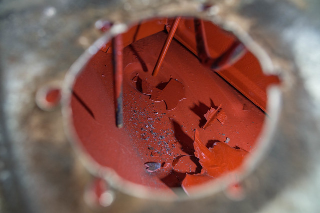
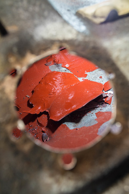
this was after I already detached the pieces with a metal stick, but you can see the epoxy accumulated in the lower part of the tank while drying and probably the difference in thickness made it crack. When it was drying I tried to leave it in a position where the excess could drip outside the tank but evidently it wasn't enough.
With this I think I had enough: later today I will bring the tank to a professional, to see what he can do about it, and if it cost too much I will 3D scan the tank, and design the metal sheets in CAD to make a new tank from scratch, or replace large portions of it.
I wanted to make a post once I completely restored the tank but since it will take longer than expected I figured it's better if I do it now:
this is the tank sealing kit I bought. I proceeded to apply all the necessary steps: brush everything, put the solution, wait, rinse, repeat until the tank is like new, but having only few hours to spend on it each day meant that I couldn't dry the tank and immediately apply the epoxy paint.. at the end I had to plan every step to finish it in only one evening, and one of the step was to rinse completely the tank and the only place I knew to do so was the car wash, so at 10PM I put the tank in the car and went to the car wash:
then back to home, I put the tank on the heater to dry it, and using hairdryer, vacuum cleaner, etc. I managed to dry it, and at 1AM I applied the epoxy sealant.
(I can't find pictures of the sealed tank now)
then I had to wait for the epoxy to harden, and in the meantime this arrived:
Also I finally found the space to put the pump and filter, without bulging under the car, and to do that I had to make brackets for them.
This is not final, but it's already very sturdy, despite the appearance.
It became clear that I had to modify few things to mount the new big hose in the tank, and I made a new port on the top to attach everything.
..then I had no more time because of my job, and only today I manage to return to my garage and work, and I found this:
this was after I already detached the pieces with a metal stick, but you can see the epoxy accumulated in the lower part of the tank while drying and probably the difference in thickness made it crack. When it was drying I tried to leave it in a position where the excess could drip outside the tank but evidently it wasn't enough.
With this I think I had enough: later today I will bring the tank to a professional, to see what he can do about it, and if it cost too much I will 3D scan the tank, and design the metal sheets in CAD to make a new tank from scratch, or replace large portions of it.

Senior Member


Joined: Jul 2007
Posts: 363
Likes: 7
From: Worcester, UK. Ex-NZ
Nice looking work aye. Shame about the tank. Plenty of people have had great experience with POR-15 tank sealant! Just need to follow the instructions carefully haha. Although a custom tank that you designed sounds pretty good. Im sure people would be interested in that?

Thread Starter
Full Member
Joined: May 2013
Posts: 62
Likes: 9
From: Florence, Italy
Sorry but I had been very busy at work and didn't have much time for the car, but also I had a really hard time to find someone willing to open my tank and repair the mess that I caused in the first place. After weeks of search I found a radiator shop that was able to do all the work, and I took advantage of this situation, telling him to put a proper size copper fuel outlet pipe instead of the adapters I bought previously.
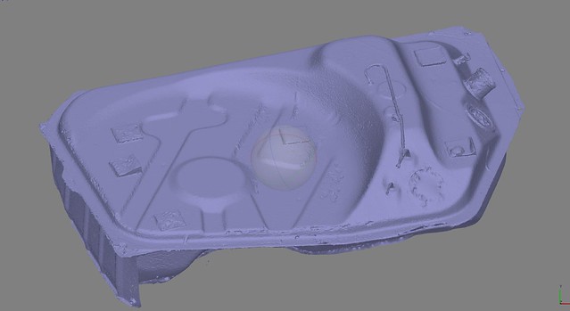
Before giving the tank to the welder guy I tried to do a 3D scan of it, so I would eventually be able to rebuild one from scratch or cut exact patches for it:
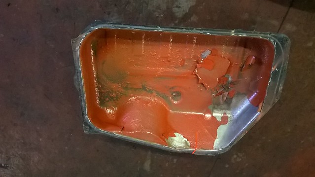
This is how it was inside before cleaning:
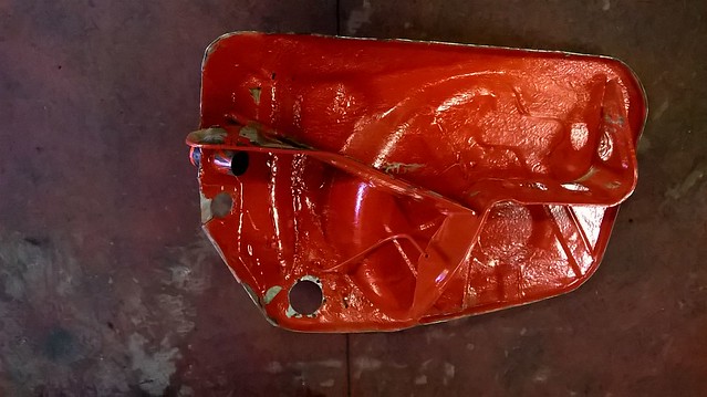
And this is after with the new pipe being welded:
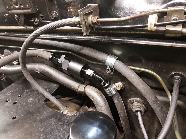
With the tank finally completed I was able to position the hoses, filters, pump etc.
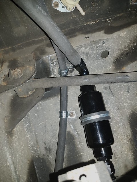
It's a tight fit but I have not much alternatives.
I don't have much space to work, and of course it's nearly impossible to take good pictures, but I try my best.

Now it's all in a temporary fit, just to see if it works and nothing hits while driving.
Next step will be the electrical connections and starting the car, I hope in a week to have the engine running.
Before giving the tank to the welder guy I tried to do a 3D scan of it, so I would eventually be able to rebuild one from scratch or cut exact patches for it:
This is how it was inside before cleaning:
And this is after with the new pipe being welded:
With the tank finally completed I was able to position the hoses, filters, pump etc.
It's a tight fit but I have not much alternatives.
I don't have much space to work, and of course it's nearly impossible to take good pictures, but I try my best.
Now it's all in a temporary fit, just to see if it works and nothing hits while driving.
Next step will be the electrical connections and starting the car, I hope in a week to have the engine running.
Thread Starter
Full Member
Joined: May 2013
Posts: 62
Likes: 9
From: Florence, Italy
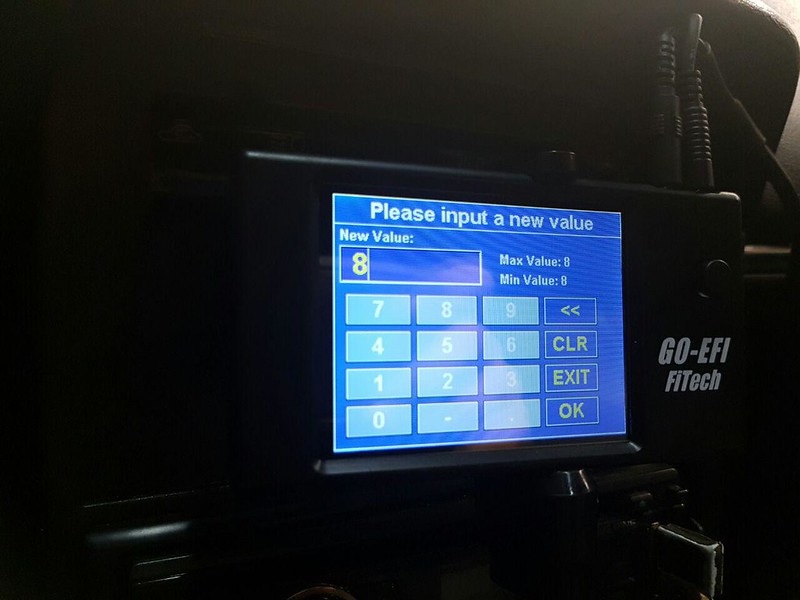
I wired everything and I began to do the initial setup, but I'm stuck because the menu doesn't let me choose anything other than 8 cylinders.. I'll write an email to Fitech, in the meantime someone has any idea abut how to circumvent this problem?
Thread Starter
Full Member
Joined: May 2013
Posts: 62
Likes: 9
From: Florence, Italy
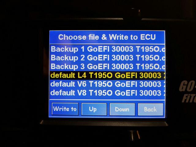
After 3 e-mails and 3 days finally I had an answer from Fitech, and as I imagined it was simple: on the controller there are few different "cal" files, and one is for the 4 cylinder engines
The software is a bit "rough", it doesn't appear very finished, but I can get around all the settings to make it work. Sadly there's no option for metric units (there's a menu option but it does nothing), that means I have to learn the fahrenheit scale and some other things to get used to.
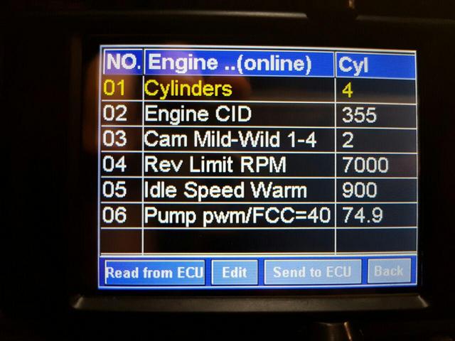
As you can see now 4 cylinders is selected, and like before, you can't actually change it from the menu, but this is not a problem. Also I copied the EFI memory on my PC, so I can poke around in the code to see how it works (in my job I'm used to reverse-engineering machine code for CNC industry so it shouldn't be a problem).
Now I need some data, especially AFR for rotary engines, because to get it to work I had to set the AFR very, very rich. 12.6 at idle to not stall... I'll check for vacuum leaks and I will try to data-log the next session. However, the car is alive and the motor runs, so I'm ALMOST satisfied.
BTW, the pump is loud as hell, maybe it's some air.
I hope other people, like Jata here, will try to do the same so we can share our maps and make it a bit easier for future users.
The software is a bit "rough", it doesn't appear very finished, but I can get around all the settings to make it work. Sadly there's no option for metric units (there's a menu option but it does nothing), that means I have to learn the fahrenheit scale and some other things to get used to.
As you can see now 4 cylinders is selected, and like before, you can't actually change it from the menu, but this is not a problem. Also I copied the EFI memory on my PC, so I can poke around in the code to see how it works (in my job I'm used to reverse-engineering machine code for CNC industry so it shouldn't be a problem).
Now I need some data, especially AFR for rotary engines, because to get it to work I had to set the AFR very, very rich. 12.6 at idle to not stall... I'll check for vacuum leaks and I will try to data-log the next session. However, the car is alive and the motor runs, so I'm ALMOST satisfied.
BTW, the pump is loud as hell, maybe it's some air.
I hope other people, like Jata here, will try to do the same so we can share our maps and make it a bit easier for future users.
Thread Starter
Full Member
Joined: May 2013
Posts: 62
Likes: 9
From: Florence, Italy
Thank you very much for the advice, until now I had to tune the carb by feeling or ear, so I never knew at what AFR runs a rotary.. so what other base values you think should I use, for cruising and WOT? are there any papers or books on the subject?
Nice work on the tank redo. Do you know the process the shop used to coat the inside? I'm guessing they welded the tank back together and then coated the inside. Do you know what product they used?
Thread Starter
Full Member
Joined: May 2013
Posts: 62
Likes: 9
From: Florence, Italy
They told me they did just the tinning of the bottom on other tanks and they never had problems. I'm skeptical but it's not like I have many choices. BTW I didn't like the guy: he knew that I already went to 4 or 5 other shops and no one wanted to bother with my tank once they had seen the epoxy inside, so he knew he could ask me a higher price and I would accept it, and so I did. shady guy to say the least. Also he lost my tank heat shield on the muffler side...
Thread Starter
Full Member
Joined: May 2013
Posts: 62
Likes: 9
From: Florence, Italy
At this point I'm not even surprised: on monday I tried to continue my setup, the car didn't start. no spark from leading side (DLDFIS). I'm still using the j-105s, could they die at the same time?
Since I'm taking them out to test them, I might as well change them with a newer, safer type of ignitor.
Since I'm taking them out to test them, I might as well change them with a newer, safer type of ignitor.

ancient wizard...
Joined: Sep 2014
Posts: 2,335
Likes: 262
From: Maryland
Do you still have original distributor in car? Before you tear everything apart,check the quality of signal(if any) from leading signal generator in distributor. To have both igniters fail simultaneously is quite a coincidence. A multimeter set on lo AC volts scale would tell you if you had voltage being generated,but a scope would be better to see exactly what's going on.