
Rogue Fabrication 1993 RX-7 build: cruise/autoX


Thread Starter
Full Member
iTrader: (2)
Joined: Feb 2013
Posts: 158
Likes: 0
From: Pacific Northwest
Rogue Fabrication 1993 RX-7 build: cruise/autoX
After a few years of owning a small business and working way too many hours, I have finally been able to afford a little treat for myself, a white FD RX-7. I spent a while looking for one with cash in hand, and then came across Phat's 1993 single turbo he spent 10 years enjoying and modifying. He blew up the first motor during an overheating issue, and had a JDM motor rebuilt and installed, and a very impressive list of modifications that went well with my tastes overall.
I flew from Portland to LA to check the car out. Airport security kept my wrenches that were over 10 inches long (whatever), and I arrived with most of my tools. When I checked the car out, I noticed it needed tie rod ends, wiring work, new door seals, some interior work, and only the tach and oil pressure gauges worked. It also was deafening at any RPM with the high flow 3 inch exhaust and open wastegate, and had a new Garrett T67 turbo installed and hadn't been to a tuner since, and thus was in need of a tune before being boosted. The car had a severe oil leak and also had a battery draining issue, and ran a little hot due to a lack of any radiator or intercooler ducting, but Phat assured me the motor had never seen over 90 degrees C. I made the 1000 mile drive over the mountain passes without boosting the car over 4 psi or exceeding 88 degrees C. I was able to monitor most of the car's vitals with the Power FC.
Plans for the car are to make it a comfortable cruising car, ie: reasonably quiet, decent seats, good sounding stereo, reliable for an FD, and a good balance of power and handling. This car will also likely see a few auto cross trips per year as well.
Here is the original mod list when I bought the car:
-Shine Auto Project Burnout Widebody Kit:
-Street Ported Motor
-Garret T61 T04S turbo
-Apexi PowerFC
-FMIC/ HKS SSQV
-Bosch 1680cc secondary injectors
-Crane Hi-6 Ignition Amplifier
-TEIN SuperStreet Adjustable Coilovers
And a pic as it was when I bought it (in'n'out burger in Redding, CA, last one on the way to Portland!
Thread Starter
Full Member
iTrader: (2)
Joined: Feb 2013
Posts: 158
Likes: 0
From: Pacific Northwest
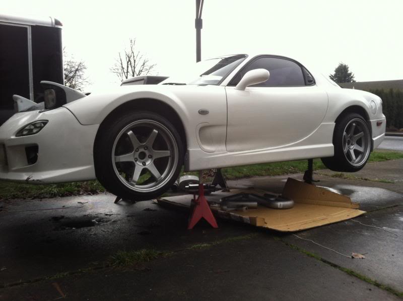
First on the list was to get it up off the ground. It looked and handled well slammed, but wasn't very streetable. I adjusted the teins up about .75" all the way around.
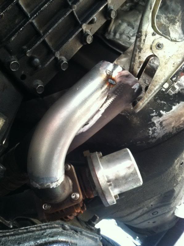
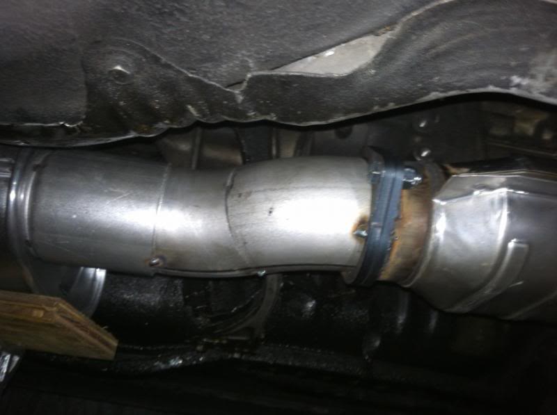
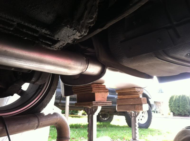
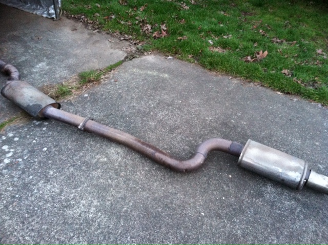
Next was getting tags. That means a cat for the visual inspection in oregon, and an airpump to keep the sucker HOT. I made a full exhaust with a removable cat/test pipe, a black halo resonator, a summit racing resonator, and two dynomax mufflers. Everything is in series. Exhaust is 3", all gradual mandrel bends. No fancy tip at the back, just a turn down to keep the bumper from getting damaged. It still is load at idle, but it is quiet at all other RPMs. And I am aware I will be repacking the fiberglass packing in the mufflers with stainless after about 3-4 hours of use
Recirc wastegate:
Cat and bends tacked up, 1st muffler visible. The cat gets replaced with a black halo res:
Big muffler in the back:
And here it is after the suspension adjustment. It can be taken over speedbumps and into driveways now.
Last edited by RogueFab; Sep 18, 2013 at 05:54 PM.
Thread Starter
Full Member
iTrader: (2)
Joined: Feb 2013
Posts: 158
Likes: 0
From: Pacific Northwest
Car jacked up high for exhaust work:
Old exhaust:
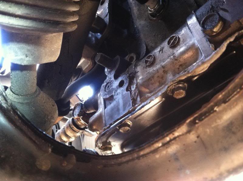
Air pump hose from cat. Bent up 3/4" x.095 tube goes up the firewall from the cat, and it converts to soft hose once the heat risk is gone.
Air pump from a vette. And IC/radiator ducting. What ducting? Air pump is zip tied in with a hack wiring job, it won't be here long
Found the oil leak. Bad crush washer on the oil cooler line.
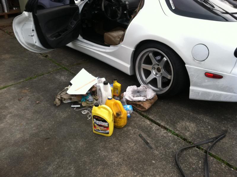
There was So much stuff int his car! A bunch of junk... And a SNAP-ON 1/2" torque wrench. Many screwdrivers, sockets, fuses, etc. And a halon fire extinguisher! Worth cleaning for the two "treats" I found.
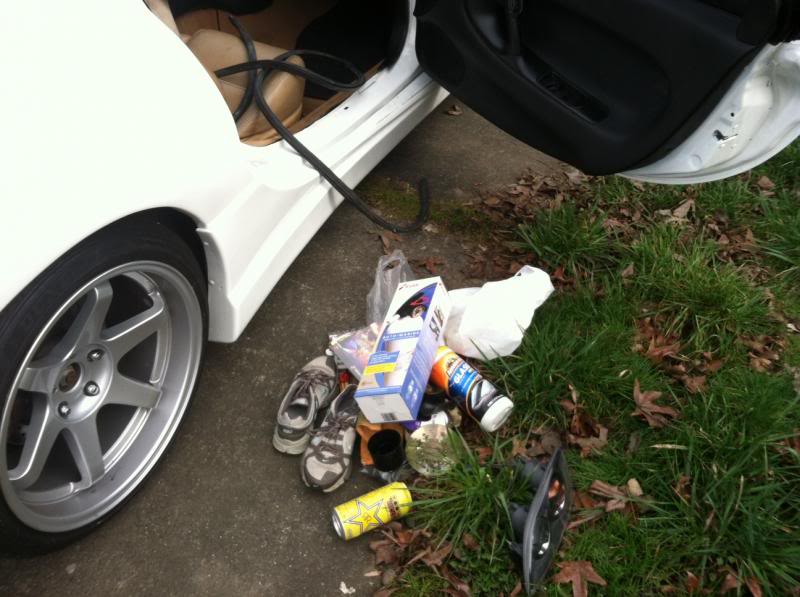
These pics aren't even all of it.
Old exhaust:
Air pump hose from cat. Bent up 3/4" x.095 tube goes up the firewall from the cat, and it converts to soft hose once the heat risk is gone.
Air pump from a vette. And IC/radiator ducting. What ducting? Air pump is zip tied in with a hack wiring job, it won't be here long
Found the oil leak. Bad crush washer on the oil cooler line.
There was So much stuff int his car! A bunch of junk... And a SNAP-ON 1/2" torque wrench. Many screwdrivers, sockets, fuses, etc. And a halon fire extinguisher! Worth cleaning for the two "treats" I found.
These pics aren't even all of it.
Last edited by RogueFab; Sep 19, 2013 at 09:41 AM.
Thread Starter
Full Member
iTrader: (2)
Joined: Feb 2013
Posts: 158
Likes: 0
From: Pacific Northwest
After all the exhaust work and air pump installation I was off to DEQ. Flipped on the air pump switch and it passed with flying colors (it failed miserably when I took it through for a baseline as I bought it). I ran the test without premix, and I mixed as soon as I got off their lot.
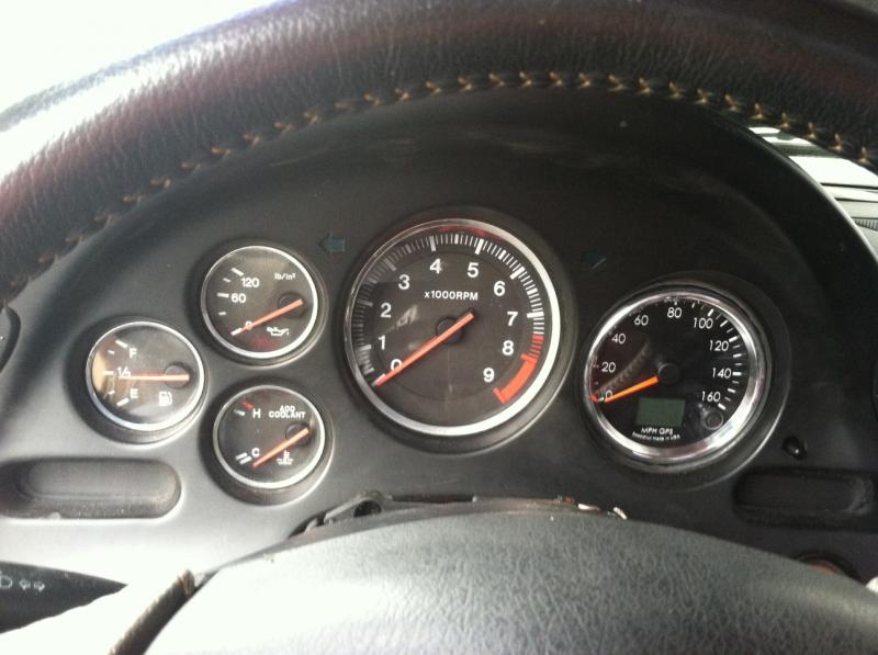
Driving around with no gauges was driving me nuts.
Water temp gage- This was a disconnected wire at the sending unit. Easy fix.
Fuel gauge- I pulled the sending unit and tested it with an ohm meter. Tested fine. I noticed the whole fuel pump mount was bent and the pump was rotated. I straightened everything out, cleaned it up, reinstalled it, and it works now. The float was stuck under a baffle from the fuel pump install that wasn't done all that well.
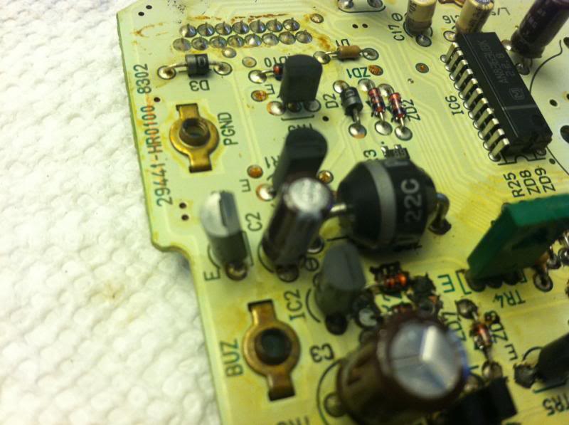
Speedometer- See pic below. Looked like the typical capacitor issue. I tried several times replacing various components, but never got it working very well. I cut the odometer off the board and desoldered the speedometer one last time and made a few other adjustments to make room for a new gauge in front of the speedo board. I had to retain the speedo board to drive the tach. The new gauge is a digital/analog GPS speedometer with built in odometer. No more speed sensor, just a GPS antenna. Simple, reliable, and stock location. Pics to come soon.
While I had the dash out, I replaced the old Sony head unit with a new Alpine, cleaned up the wiring, and found a high resistance short that was draining the battery through the original stereo power source. My static battery current draw went from 180mA down to 46mA. 46 is still too high, but should give me a week or two in between starts without needing a tender. I also installed an innovate MTX-L wideband O2 sensor and gauge in preparation for having the car dyno tuned.
Up next... the trip to the dyno.
Speedo board with some leaky crap and blackness:
Driving around with no gauges was driving me nuts.
Water temp gage- This was a disconnected wire at the sending unit. Easy fix.
Fuel gauge- I pulled the sending unit and tested it with an ohm meter. Tested fine. I noticed the whole fuel pump mount was bent and the pump was rotated. I straightened everything out, cleaned it up, reinstalled it, and it works now. The float was stuck under a baffle from the fuel pump install that wasn't done all that well.
Speedometer- See pic below. Looked like the typical capacitor issue. I tried several times replacing various components, but never got it working very well. I cut the odometer off the board and desoldered the speedometer one last time and made a few other adjustments to make room for a new gauge in front of the speedo board. I had to retain the speedo board to drive the tach. The new gauge is a digital/analog GPS speedometer with built in odometer. No more speed sensor, just a GPS antenna. Simple, reliable, and stock location.
Pics to come soon.While I had the dash out, I replaced the old Sony head unit with a new Alpine, cleaned up the wiring, and found a high resistance short that was draining the battery through the original stereo power source. My static battery current draw went from 180mA down to 46mA. 46 is still too high, but should give me a week or two in between starts without needing a tender. I also installed an innovate MTX-L wideband O2 sensor and gauge in preparation for having the car dyno tuned.
Up next... the trip to the dyno.
Speedo board with some leaky crap and blackness:
50 mv or less draw is considered normal for most cars. I'm wouldn't be surprised to see 46 the normal, i've had to fix a draw on a bmw or two and they stayed at around 30-50 after everything went to sleep.
keep up the good work on a stunning looking FD.
keep up the good work on a stunning looking FD.
Trending Topics
Thread Starter
Full Member
iTrader: (2)
Joined: Feb 2013
Posts: 158
Likes: 0
From: Pacific Northwest
Rear: 18x10.5 +22, 255/35R18
They are stretched a bit much for my taste, I will articulate the suspension and see if I have room for something a little wider so mount more normal/safe when they wear out.
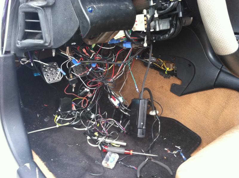
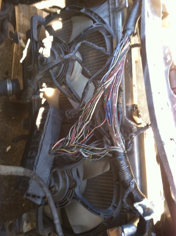
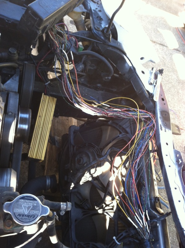
Here is some wiring I have been working on cleaning up a little. Someday I will pull the dash and do it 100%. Mostly an alarm, gauges, turbo timer, and numerous stereo installs, done at separate times with no real major plan by the previous owner. I am very good with wiring, and I look forward to doing it right.
Here is the GPS speedo installed. With the single odometer reset button you can toggle between compass, digital speed display, 1/4 mile time, 0-60 time, etc. Neat little gadget.
Thread Starter
Full Member
iTrader: (2)
Joined: Feb 2013
Posts: 158
Likes: 0
From: Pacific Northwest
They also read your correct speed while your tires are not going the same speed as your vehicle

Thread Starter
Full Member
iTrader: (2)
Joined: Feb 2013
Posts: 158
Likes: 0
From: Pacific Northwest
We chose to distribute their products and use them on customer's cars because they were made in the USA, and because they stand behind their products. But all the features they cram into their speedos don't hurt either.
Installed new door seals (Mazda OEM only, ouch! $$$)
Sourced a FD spare tire and installed it
This car does the click-click-start thing. I installed a new engine ground, and tried bypassing the clutch switch and starter interrupt relay, no luck. I will be building a starter relay amp circuit. If Dale did it, it must be a worthy mod.
The 47mA battery draw seems fine. Car sat for 7 days and had plenty of juice to start.
Thread Starter
Full Member
iTrader: (2)
Joined: Feb 2013
Posts: 158
Likes: 0
From: Pacific Northwest
Car got new tie rods and was corner balanced. 53% rear weight bias.
Also got dyno tuned at PRE in Portland, Oregon. Car was overboosting, so they returned it to me (I didn't let them to replace my wastegate for $650). I found out my old HKS wastegate has a 1.2+ bar spring in it, and nobody sells springs for them now.
I am an engineer, so I got out a spring catalog and started calculating cycle life and deflected loads on springs. Found 4 that will work at various pressures with good stress numbers and short enough solid heights. I made a pressure regulator manifold to test the wastegate with, and tested all 4 springs. I ended up with 2,3,6, and 8 PSI springs. I installed the 6 and the boost controller, and sent the car back.
They had issues with my boost controller (Old School Greddy), so they installed a MBC for me to get the tune done. Car would hit 11 Psi and then drop to 6.5 by redline. I think they left a line unplugged. Made 240 HP at 6.5 Psi. I paid them their $700 and left.
Car still idles like ****, and per my Wideband, the car is running pig rich at any RPM and throttle position above 15% (about 7.5 to 1), and super lean at idle (20+ to 1). Not exactly an ideal tune, but they have done a lot of these cars, so it must work okay.
Next up, radiator and intercooler remounting, replumbing, and custom ducting. Time to get this car COOL. Then get the boost up to a steady 10-11 Psi.
Thread Starter
Full Member
iTrader: (2)
Joined: Feb 2013
Posts: 158
Likes: 0
From: Pacific Northwest
No kidding. Once I sort out the boost and the airflow to the rad/ic, I should be around 300, which is what I want. I know the mods the previous owner did are capable of a lot more, but it would need more to do it safely (meth or water injection, a much better tune, some new sensors, etc.). The tuner said he made sure the fuel map looked right at higher airflow values for when the boost control issue is fixed, that way it won't blow up at 11psi before getting re tuned.
Thread Starter
Full Member
iTrader: (2)
Joined: Feb 2013
Posts: 158
Likes: 0
From: Pacific Northwest
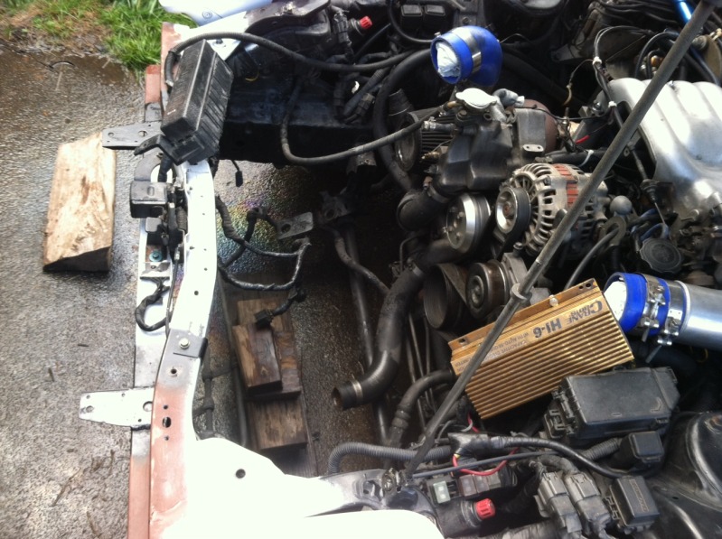
Here is the new engine ground. I only had red wire in a decent gauge, so that's what I used...
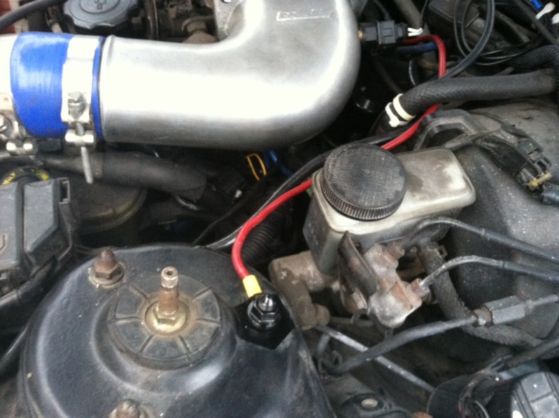
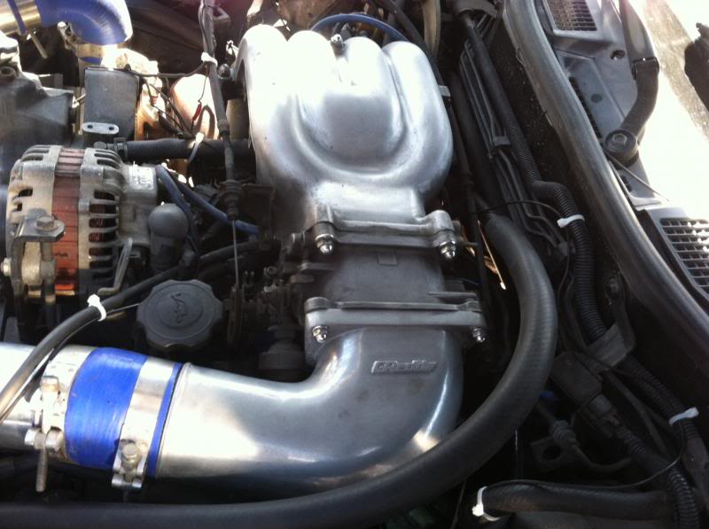
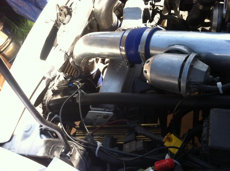
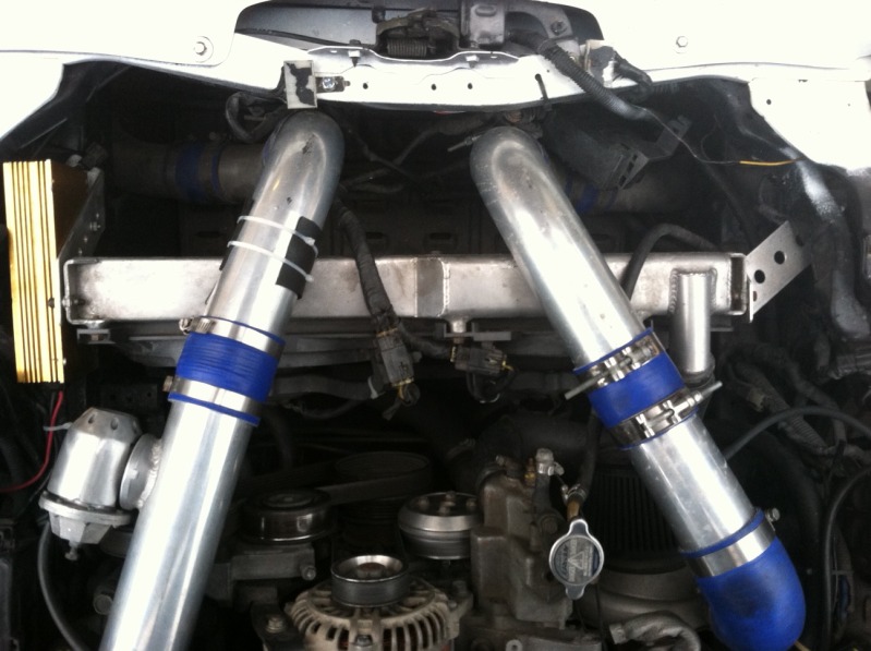
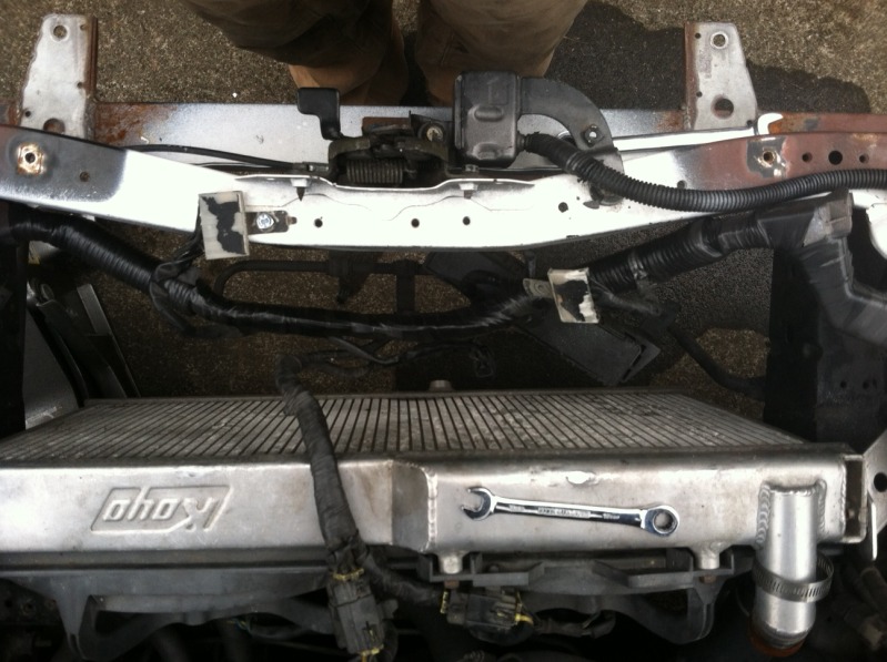
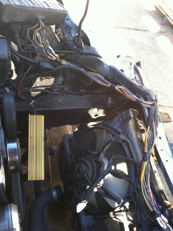
Here is the starting point with the IC pipe routing and radiator position:
Shine Auto bumper cover removed. No surprise, bumper core is gone:
Re-wrapped the harness in E tape real quick:
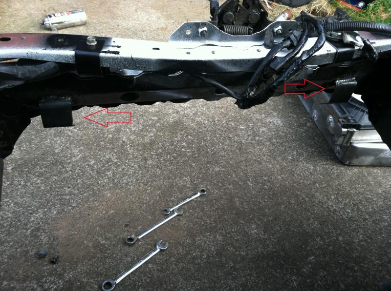
Cut a couple pieces of 16 ga sheet metal to make harness brackets:
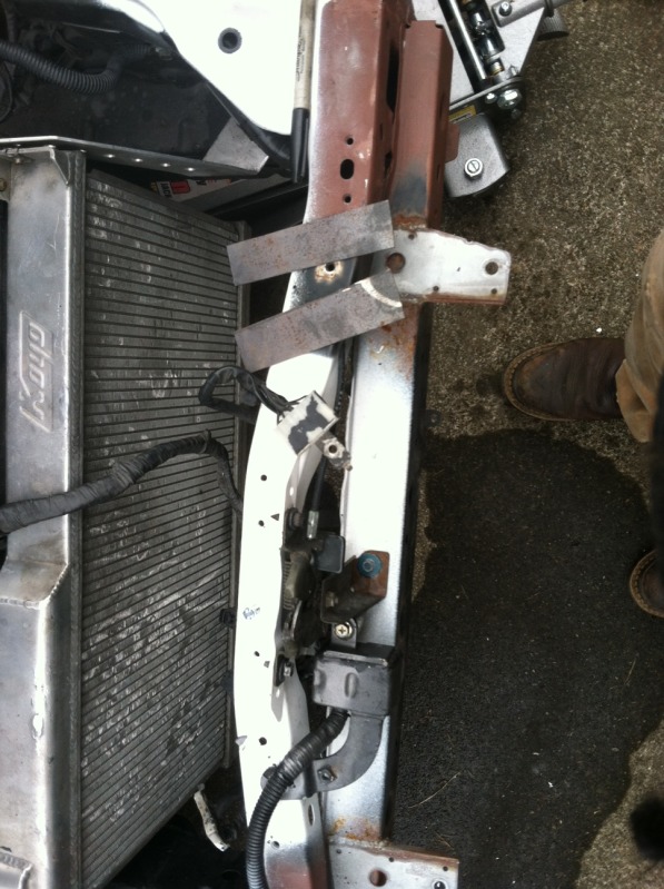
Bent up and drilled:
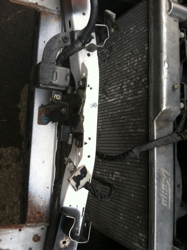
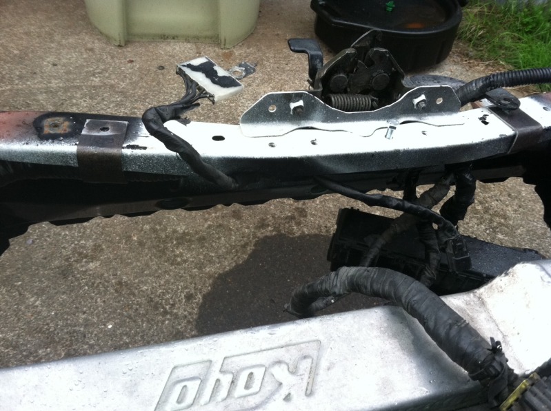
Test fitting. Tucks the harness up nicely where it belongs.
The plan is to stack the intercooler and radiator together sealed with removable sheet metal right behind/under the core support. They will be angled forward at the top. This will allow a mild expansion chamber in front of the exchangers to increase static pressure before the intercooler. Air will exit via a reducing cross section duct that will dump out the hood into the high velocity (low pressure) air stream. The reducing area exit will increase the air velocity back up to close to the external stream speed, which helps with drag and efficiency, though my main reasons are packaging and engine bay temp management related. This setup should naturally move a lot of air, create good turbulent flow fora high heat transfer coefficient (especially post IC, for the rad), and improve the performance of the OEM fans.
This system will be the least work if I can get the radiator lines, intercooler plumbing, and wiring out of the way. The plan is to do all 3 of these things.
This system may also have a splitter that will direct air into the engine bay in the turbo/filter area to further assist in underhood temp management. This is the part of the system that may not be possible due to space constraints.
I know you are all thinking I am nuts now. This is going to be a LONG process of prototype and fabrication. I will have pics of the process and results.
Downsides: Tougher to maintain, and no more badass FMIC filled bumper opening. Small prices to pay for cooling performance.
Why: Because V mount is too expensive and this is going to be a fun project.
Here is the starting point with the IC pipe routing and radiator position:
Shine Auto bumper cover removed. No surprise, bumper core is gone:
Re-wrapped the harness in E tape real quick:
Cut a couple pieces of 16 ga sheet metal to make harness brackets:
Bent up and drilled:
Test fitting. Tucks the harness up nicely where it belongs.
The plan is to stack the intercooler and radiator together sealed with removable sheet metal right behind/under the core support. They will be angled forward at the top. This will allow a mild expansion chamber in front of the exchangers to increase static pressure before the intercooler. Air will exit via a reducing cross section duct that will dump out the hood into the high velocity (low pressure) air stream. The reducing area exit will increase the air velocity back up to close to the external stream speed, which helps with drag and efficiency, though my main reasons are packaging and engine bay temp management related. This setup should naturally move a lot of air, create good turbulent flow fora high heat transfer coefficient (especially post IC, for the rad), and improve the performance of the OEM fans.
This system will be the least work if I can get the radiator lines, intercooler plumbing, and wiring out of the way. The plan is to do all 3 of these things.
This system may also have a splitter that will direct air into the engine bay in the turbo/filter area to further assist in underhood temp management. This is the part of the system that may not be possible due to space constraints.
I know you are all thinking I am nuts now. This is going to be a LONG process of prototype and fabrication. I will have pics of the process and results.
Downsides: Tougher to maintain, and no more badass FMIC filled bumper opening. Small prices to pay for cooling performance.
Why: Because V mount is too expensive and this is going to be a fun project.
Thread Starter
Full Member
iTrader: (2)
Joined: Feb 2013
Posts: 158
Likes: 0
From: Pacific Northwest
Well i decided there was no way to accomplish this without more mounting points on the IC and radiator. I will have to get some aluminum nuts to weld on them.
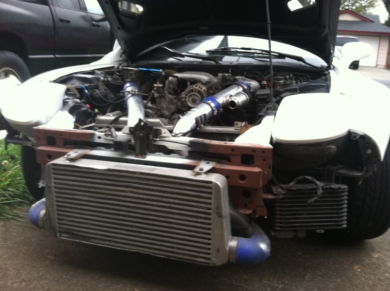
Engine bay is looking empty in the front:
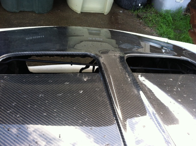
I pulled the chicken wire out of the hood (I keep my car covered, so leaves/junk shouldn't be much of a problem). Here is a shot showing the path/angle to the inlet. a little steep, but good enough:
Engine bay is looking empty in the front:
I pulled the chicken wire out of the hood (I keep my car covered, so leaves/junk shouldn't be much of a problem). Here is a shot showing the path/angle to the inlet. a little steep, but good enough:
Project looks great, coming along quickly too.
It doesn't have to be...
I used a GReddy FMIC (bought used) hacked and welded up... And a koyo n flo for cooling, brackets are literaly a 'hack job' as they were built from sheet metal, using a vice, drill press (table top version) a hack saw and a few other garage tools...
Friend did the welding for a small sum (beer) that was the biggest expense, other then the initial cost of the IC and Rad themselves
Its not pretty by any means, but it works damn good, and like other DIYer's on the forum, I built screwed up, fixed it, devised solutions for some challenges that arise...
Looking forward to seeing more done on your project...
J.
Thread Starter
Full Member
iTrader: (2)
Joined: Feb 2013
Posts: 158
Likes: 0
From: Pacific Northwest
No serious progress. Laid out where the nuts will be welded on. Sanded down to clean aluminum on the rad/IC where they will go, and then sanded down all 6 sides of 20 aluminum hex nuts and set up some time on a TIG machine with a freind.
Also inspected my intercooler. It is bent a little from a collision at some point. Proabbly a small animal or something else minor, as the car is straight.
I don't like sanding any more
mid-sanding:
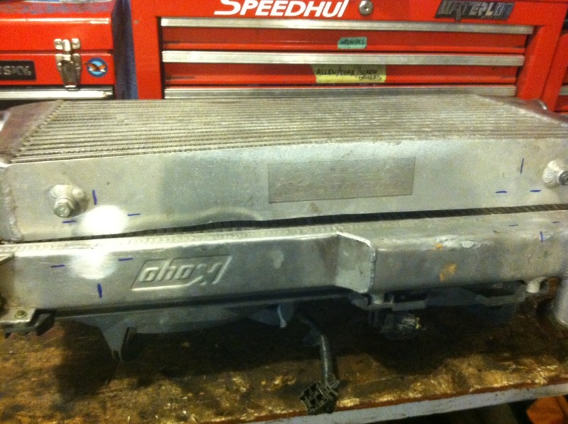
Also inspected my intercooler. It is bent a little from a collision at some point. Proabbly a small animal or something else minor, as the car is straight.
I don't like sanding any more
mid-sanding:
Cool project, that wiring looked scary!
Odd to see you on here...I was just about to buy one of your bending units I saw on a 4x4 forum. Need to make some bumpers n crap for my Ford.
Good luck!
Odd to see you on here...I was just about to buy one of your bending units I saw on a 4x4 forum. Need to make some bumpers n crap for my Ford.
Good luck!
Thread Starter
Full Member
iTrader: (2)
Joined: Feb 2013
Posts: 158
Likes: 0
From: Pacific Northwest
PM us if you have any questions.
Welding should be completed by Friday (fingers crossed).
Thread Starter
Full Member
iTrader: (2)
Joined: Feb 2013
Posts: 158
Likes: 0
From: Pacific Northwest
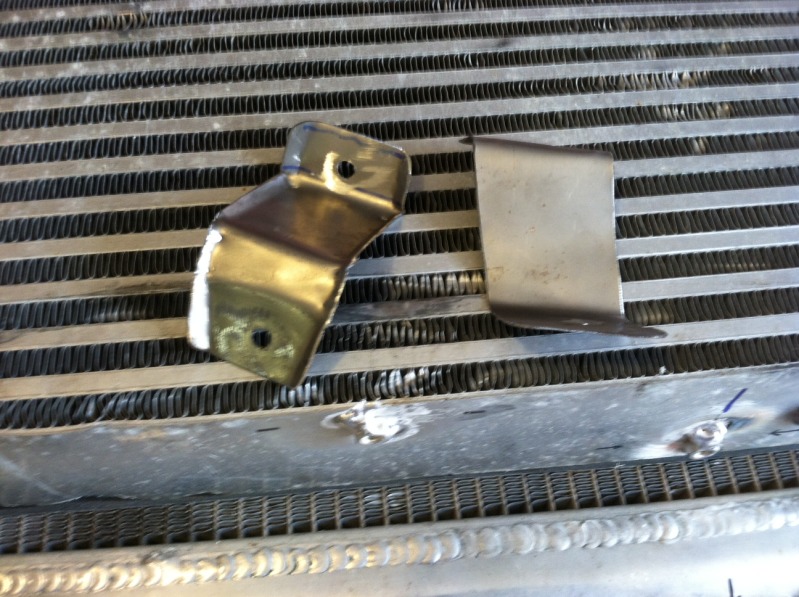
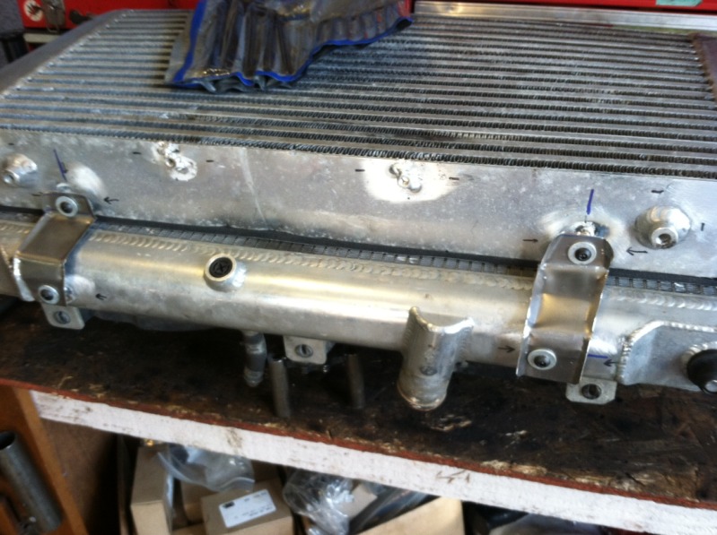
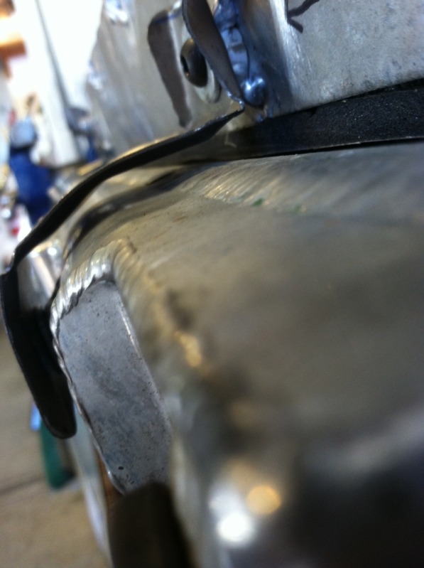
Stainless Steel mounts for IC/Rad
More
More
More
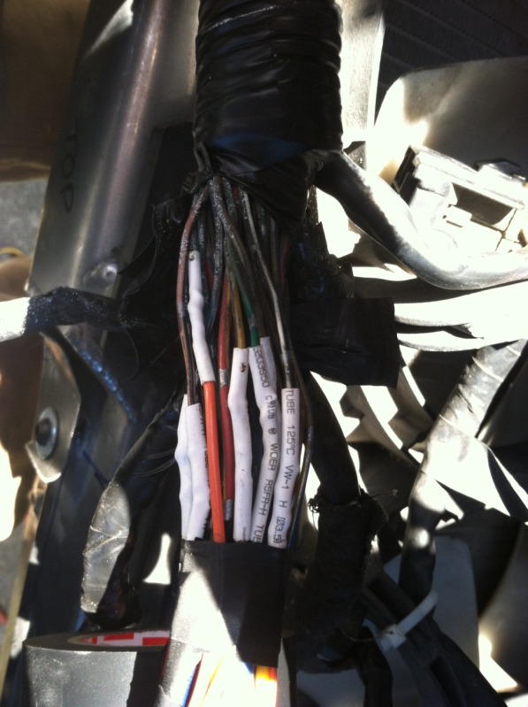
Remember that front harness I rewrapped? Well it had to move. Decided the front fuse/relay box was in my way. Off with the tape.
soldered extensions, moved a few junctions
Tape ties
Used heat shrink on every connection. Worth the extra time.
More
More
More
Remember that front harness I rewrapped? Well it had to move. Decided the front fuse/relay box was in my way. Off with the tape.
soldered extensions, moved a few junctions
Tape ties
Used heat shrink on every connection. Worth the extra time.
Last edited by RogueFab; Oct 29, 2013 at 03:10 PM.
Front: 18x9.5 +22, 235/40R18
Rear: 18x10.5 +22, 255/35R18
They are stretched a bit much for my taste, I will articulate the suspension and see if I have room for something a little wider so mount more normal/safe when they wear out.
They do look like Varrstoens. I don't think they are, probably something cheaper.
Rear: 18x10.5 +22, 255/35R18
They are stretched a bit much for my taste, I will articulate the suspension and see if I have room for something a little wider so mount more normal/safe when they wear out.
They do look like Varrstoens. I don't think they are, probably something cheaper.
thanks! i just noticed you appear to have wider fenders and the tires stretched more than i noticed at first glance. i'm trying to find which size/offset utilizes the most of the wheel well so i can run some ~285s in the rear and maybe 275 up front.
Thread Starter
Full Member
iTrader: (2)
Joined: Feb 2013
Posts: 158
Likes: 0
From: Pacific Northwest
I am behind on my updates...
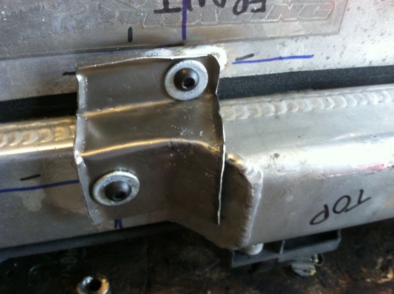
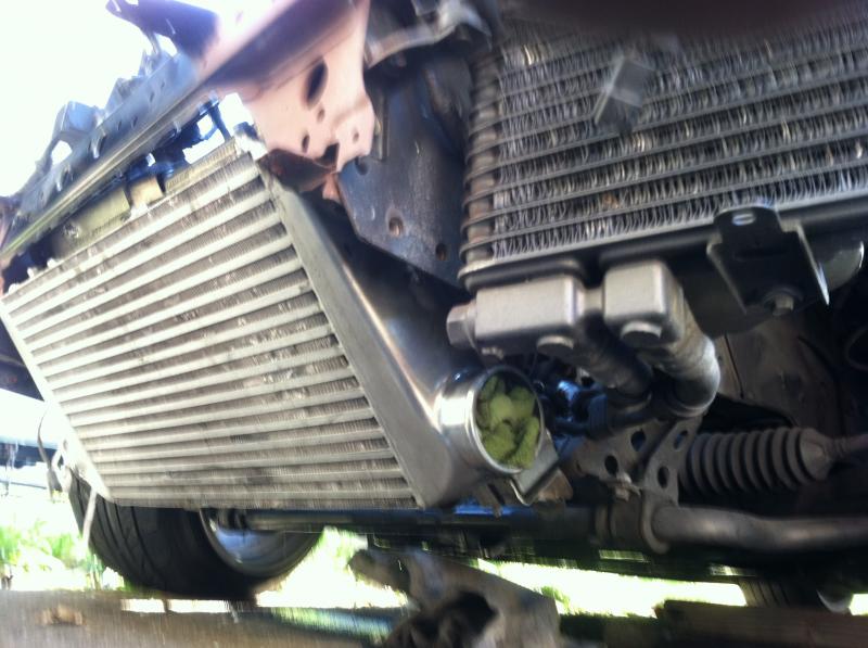
Upper intercooler mounts:
Mounted: (not seated in the hole yet)
Properly seated on this side:
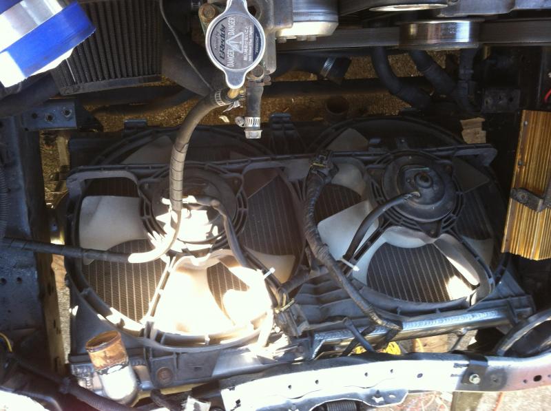
Fans from above.
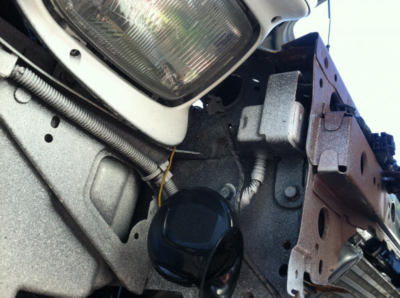
And decided to install a horn. Not sure why the car never had one when I bought it.
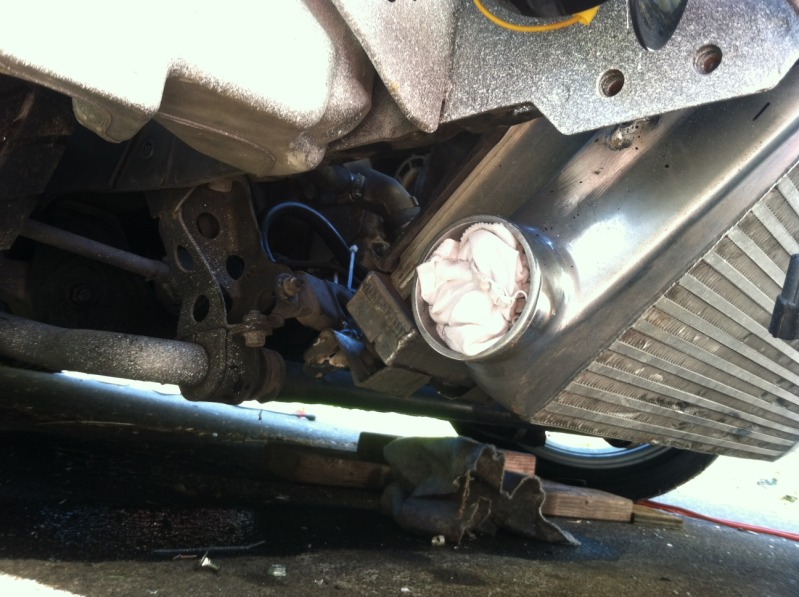
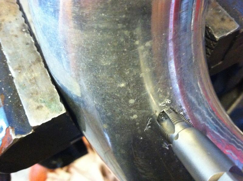
I also hacked together the intercooler piping with what I had laying around. It is about 12 inches shorter than before. Pics to follow. Here is the 1/8-NPT tapping on one of the hot pipes for my boost controller line.
Upper intercooler mounts:
Mounted: (not seated in the hole yet)
Properly seated on this side:
Fans from above.
And decided to install a horn. Not sure why the car never had one when I bought it.
I also hacked together the intercooler piping with what I had laying around. It is about 12 inches shorter than before. Pics to follow. Here is the 1/8-NPT tapping on one of the hot pipes for my boost controller line.
