
dubulup's AI Safe Boost Control

Thread Starter
development
Joined: Aug 2002
Posts: 5,714
Likes: 7
From: Lafayette, LA
dubulup's AI Safe Boost Control
Just wanted to share how I plan to run my boost control with an aggressive AI tune.
49:51 Meth/Water with a pump controller.
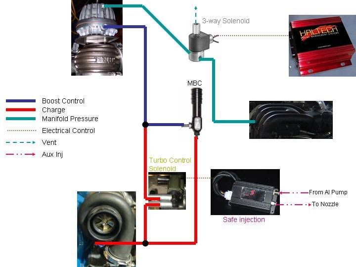
I run a MBC. The downside is spool up time and how to drop boost IF AI fails, so I've added a simple componet into the equation to aid spool up...3-way solenoid valve, and a flow meter to monitor AI.
Theory: Run 18psi aggressively on 93 oct.
Run the charge line off the compressor thru the MBC to control boost; 9psi spring in WG. Apply MAP on top of the WG to keep the WG completely closed, until 1~2psi before MAX boost (MAP will always be greater than MBC pressure). The Haltech will engerize the 3-way solenoid, venting the pressure on top of the WG thru the top of the SV (MAP signal will be blocked off at the SV in this state), allowing the MBC to take over control of the WG.
The SafeInjection module is a flow meter for the AI pressurized line. Once given a signal to start monitoring, IF for any reason the flow drops below 378 cc/min, a 12V trigger will open the Turbo Control SV, which will bypass the MBC and put the straight charge pressure to the WG, opening it fully and then holding boost to the WG spring pressure...dropping my tune back into the, safe, 93 oct tune.
Since I had a 16-17psi signal venting the 3-way SV to open the WG, the Haltech will not release that signal until boost drops below 7psi; this will allow me to run the WG spring boost IF my AI system fails (between shifts the WG will be held shut again until just before full boost is reached). I plan to add a manual over ride switch that will allow for 9psi of boost all the time; I will most likely start AI at 10psi.
As far as tuning, I will be monitoring EGT's in the exh. manifold (front and rear), a downpipe EGT (as I will try to not to cook my cat...again), and a WB O2...and I'm cooking up a dual knock monitor.
Ultimate goal...reliable safe power on the street with emissions.
I tried to give as many details as possible, this is still in the idea phase, and I've probably over looked some tweaking details, so please speak up and share your opinions and/or idea's.
ps.I like my MBC, so please don't suggest an EBC


Joined: Oct 2001
Posts: 6,279
Likes: 728
From: Florence, Alabama
very nice setup.
i imagine you plan to start your AI above your WG spring boost pressure so you will revert to an all gas base fuel map. i considered your setup and decided to do a J&S knock retard instead. i do start my AI at 5.5 psi but imagine i could start it above WG base spring pressure.
i do like the Snowperformance flowmeter.
nice ideas, helpful post.
howard coleman
Thread Starter
development
Joined: Aug 2002
Posts: 5,714
Likes: 7
From: Lafayette, LA
That is the plan...all pump gas tune for everything under the WG spring. Have a quick car setting at 9psi (low stress)...and have a really quick car setting with twice the boost, and set up to handle it.
I'm not really going for BIG numbers, I'm going for the long haul...I don't want to pull another motor out of this car for 50k miles (clutch and tranny jobs included)...I'm sure I'll be more than pleased where she ends up.
I'm not really going for BIG numbers, I'm going for the long haul...I don't want to pull another motor out of this car for 50k miles (clutch and tranny jobs included)...I'm sure I'll be more than pleased where she ends up.
Thread Starter
development
Joined: Aug 2002
Posts: 5,714
Likes: 7
From: Lafayette, LA
I started my install and figured I'd share some progress (mainly because I'm excited how clean it is coming along)
Here is the stock (two speed) fuel pump wiring diagram. The L/W wire off the "Speed" relay is triggered by the ECU. Since I run a Haltech, this entire circuit is unused.
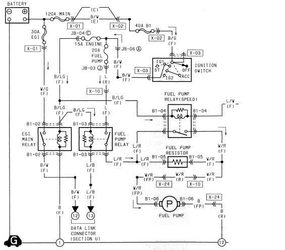
I've turned it into my Auxilary Injection circuit. I have removed the Fuel Pump Resistor and the "Speed" relay. The resistor connector (located under the cruise control) now powers my Progressive Pump Controller. L/R -> R - 12V, B - GND, W/R -> G - Output to pump. The 3 new wires added are no longer than 6 inches. Key On = Pump controller has power. The controller will get its boost source from behind the UIM.

This picture shows locations (if you aren't familiar with an FD). Pump controller is under the cruise control...powered by the AI relay (fuel pump fuse under the dash is now the AI fuse), and I call it the Safe Injection jumper location, because that is where I pulled the "speed" relay, and will trigger the SI module from the wire W/R wire that connects the FP resistor to the original circuit (now powering the AI pump). The SI flow meter become active once the pump is turned on...there is a delay adjustment as well; 0.0-0.6s. Then I send the SI "ALARM" trigger down chassis harness to the stock ECU location via the L/W wire...where I'll jump the L/W into my Haltech harness. I already have a solenoid mounted under the UIM I used for boost control, so I just need to change what controls it (haltech -> SI)
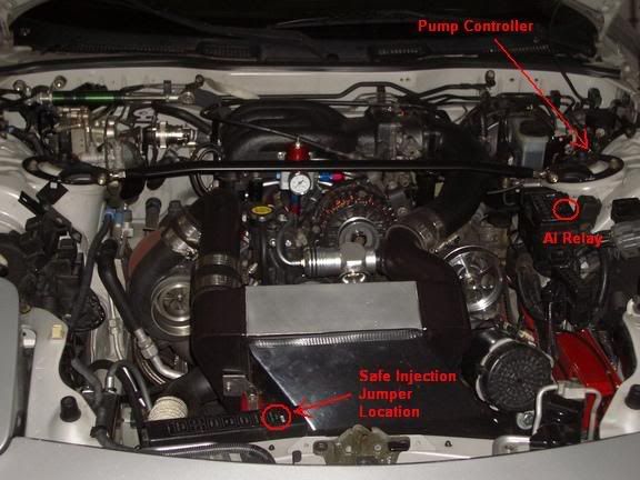
This last picture shows where I plan to mount my SI module...directly on the IC end tank. You can also see my nozzle location on my outlet pipe. Again the 3 wires added are fairly short and hidden.

comments/suggestions?
Here is the stock (two speed) fuel pump wiring diagram. The L/W wire off the "Speed" relay is triggered by the ECU. Since I run a Haltech, this entire circuit is unused.
I've turned it into my Auxilary Injection circuit. I have removed the Fuel Pump Resistor and the "Speed" relay. The resistor connector (located under the cruise control) now powers my Progressive Pump Controller. L/R -> R - 12V, B - GND, W/R -> G - Output to pump. The 3 new wires added are no longer than 6 inches. Key On = Pump controller has power. The controller will get its boost source from behind the UIM.
This picture shows locations (if you aren't familiar with an FD). Pump controller is under the cruise control...powered by the AI relay (fuel pump fuse under the dash is now the AI fuse), and I call it the Safe Injection jumper location, because that is where I pulled the "speed" relay, and will trigger the SI module from the wire W/R wire that connects the FP resistor to the original circuit (now powering the AI pump). The SI flow meter become active once the pump is turned on...there is a delay adjustment as well; 0.0-0.6s. Then I send the SI "ALARM" trigger down chassis harness to the stock ECU location via the L/W wire...where I'll jump the L/W into my Haltech harness. I already have a solenoid mounted under the UIM I used for boost control, so I just need to change what controls it (haltech -> SI)
This last picture shows where I plan to mount my SI module...directly on the IC end tank. You can also see my nozzle location on my outlet pipe. Again the 3 wires added are fairly short and hidden.
comments/suggestions?
Joined: Oct 2001
Posts: 6,279
Likes: 728
From: Florence, Alabama
very nice and thanks for sharing.
my question is:
with a drop below XXX flow you electrically/instantaneously trigger what is a mechanical safeguard, ie the wastegate solenoid. i will be very interested in the time lag from the electrical impulse of lowered flow and the partial (spring rate) boost release in relation to the ensuing lean condition brought on by the decreased flow. if it takes any time at all to lower the boost it may be after the fact.
it may work because the flow decrease occurs before the motor goes lean. operative word being "may."
perhaps a better boost related safeguard would be to energize a blow-off valve as you might vent more pressure. maybe fixtured as additional?
i think a pure electrical safeguard might work better since it would happen immediately.
lots of questions, not many solid answers. perhaps Snow has the answers... perhaps they have given them to you
howard coleman
Thread Starter
development
Joined: Aug 2002
Posts: 5,714
Likes: 7
From: Lafayette, LA
I plan to do simple tests...after I get a good base at 9psi, then tune up to 10-11psi with pump fuel, and arm the SI just to see what the "no flow" situation brings...I hope it just opens the WG and brings me back the the safe map area of a solid 9psi.
I am also curious as to how the motor will respond to a more dramatic response
(15+psi ->9psi)...but I hope to never incounter it.
You do bring up an interesting approach, I haven't thought to induce a BOV...but I guess that is as much plumbing as what I've already thought out. Just have the solenoid give a straight vacuum source from the intake to the BOV. Then instead of feeling a drop in power, you have a BOV noice (at WOT)alarming you to the condition...a major leak in power.
I'd still want a manual switch that over rides the AI and gives me a safe WG spring tune.
Interesting...thanks for the food for thought.
Eats, Sleeps, Dreams Rotary
iTrader: (1)
Joined: Jul 2001
Posts: 3,383
Likes: 3
From: Stinson Beach, Ca
seems like a good plan, i like it.
any links to some other 49/51 water/meth threads? i assume you're talking about boost juice? Was looking at the same thing.
any links to some other 49/51 water/meth threads? i assume you're talking about boost juice? Was looking at the same thing.
Trending Topics
i think Howards idea of a blow off solenoid is probably the best idea since the reaction time will be maximized that way, the wastegate timing will probably be too slow mainly because the mass of the turbine spinning will be slower to drop boost than simply venting it off in the intake tract.
Joined: Oct 2001
Posts: 6,279
Likes: 728
From: Florence, Alabama
the energized blowoff valve idea was wrong on my part... i typed blowoff valve but was thinking "pop-off" valve. greddy makes them and they would probably vent more and be faster.
howard coleman
howard coleman
Thread Starter
development
Joined: Aug 2002
Posts: 5,714
Likes: 7
From: Lafayette, LA
Yes, I was talking about the boost juice...don't know any other companies. mixing it yourself might be cheaper.
I'm still deciding what to do with the trigger. Leaning heavily towards what I have drawn above. Logic being...at max boost I'll be injecting AI ~500cc. The trigger will be thrown at 75% flow. Since I'm driving a street car...I won't be tuning to the ragged edge.
I suppose a sure fire method of tuning would be to tune max boost at 75% AI, and run the system with the 25% safety blanket (at the expense of a few hp).
Thread Starter
development
Joined: Aug 2002
Posts: 5,714
Likes: 7
From: Lafayette, LA
Just some pic update (almost ashamed how dirty my car looks)
on left is the Electric Air Pump, and right is the Pump Controller power to the Safe injection...then the trigger into the harness, to a relay then to the solenoid.

the safe injection slips into a pocket just in front of my MSD (the sleeved harness extends to the air pump).

Here is the pump controller

A blurry picture of the res. and pump...

lastly, the pineapple dual EGT gauge and thermal couplers

the safe injection slips into a pocket just in front of my MSD (the sleeved harness extends to the air pump).
Here is the pump controller
A blurry picture of the res. and pump...
lastly, the pineapple dual EGT gauge and thermal couplers
Thread Starter
development
Joined: Aug 2002
Posts: 5,714
Likes: 7
From: Lafayette, LA
Originally Posted by dubulup
I'm still deciding what to do with the trigger.
Anyone think hitting fuel cut with over 500cc's of 50/50 mix could cause a problem? should my overboost action be ignition cut?
I think I'm finally coming around with howard coleman's reasoning behind a purely electrically fail safe. I think the easiest way would be to cut the 12V line to my fuel injectors...hit the "wall", foot comes off the pedal, boost is gone (flip the safe 93 tune switch - held to WG spring). I've never been a fan of ignition cut, but this can be achieved in the same manner...if recommended.
question I have is...would one be safer than the other? If the trigger is sent, that means the AI is on the downward ramp already, so maybe I shouldn't be concerned with that.
comments?
Thread Starter
development
Joined: Aug 2002
Posts: 5,714
Likes: 7
From: Lafayette, LA
REV C - after some food for thought.
This is my plan...I think I'll combine two idea's into one. The first is my original WG solenoid idea...but has howard coleman pointed out, this will not react fast enough due to the 13B acting like a 2-stroke; many combustion cycles could occur in the time it takes to drop boost.
My Haltech has the option for dual maps...one will be the main (safe up until 10psi, then after using AI) and the secondary will be a rich/retarded map for AI failure to cover the few seconds it takes for my boost to drop.
so instead of cutting fuel or ignition, I'll add fuel and drop timing while dropping boost.
Here is some info on Dual Maps (some a little more than you need...concerning set-up)
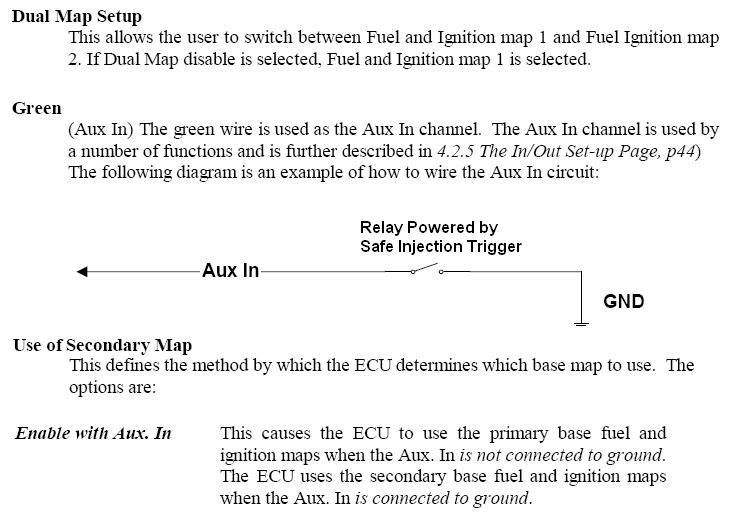
and of course my diagram to get the idea on the table. I'll need to use a relay, so the 12V trigger will actually ground the Green wire to the Haltech.

My Haltech has the option for dual maps...one will be the main (safe up until 10psi, then after using AI) and the secondary will be a rich/retarded map for AI failure to cover the few seconds it takes for my boost to drop.
so instead of cutting fuel or ignition, I'll add fuel and drop timing while dropping boost.
Here is some info on Dual Maps (some a little more than you need...concerning set-up)
and of course my diagram to get the idea on the table. I'll need to use a relay, so the 12V trigger will actually ground the Green wire to the Haltech.
I'm going to do something very similar. . .only difference will be using a POV rather than the WG for pressure relief. I take it by your most recent proposal that the e6x does in fact have the feature i described on my e11v2. . .kick ***.
good luck man, definitely keep us posted.
ryan
good luck man, definitely keep us posted.
ryan
Joined: Oct 2001
Posts: 6,279
Likes: 728
From: Florence, Alabama
dubulup
that looks good. i like electrics for safeguards as you won't be closing the barn door after the horse got out.
i wish i could switch maps w the power fc.
what are the flow parameters on the Safeinjection?
howard
that looks good. i like electrics for safeguards as you won't be closing the barn door after the horse got out.
i wish i could switch maps w the power fc.
what are the flow parameters on the Safeinjection?
howard
Thread Starter
development
Joined: Aug 2002
Posts: 5,714
Likes: 7
From: Lafayette, LA
Originally Posted by big_rizzlah
I take it by your most recent proposal that the e6x does in fact have the feature i described on my e11v2. . .kick ***.
good luck man, definitely keep us posted.
ryan
good luck man, definitely keep us posted.
ryan

Originally Posted by howard coleman
i like electrics for safeguards as you won't be closing the barn door after the horse got out.
i wish i could switch maps w the power fc.
what are the flow parameters on the Safeinjection?
i wish i could switch maps w the power fc.
what are the flow parameters on the Safeinjection?
There are a lot of things I wish the PFC could do...that's the main reason, I went with the haltech, and also to make engine removal that much easier...
^few years back when I was building the haltech harness...no more digging in the interior for the ECU and pulling the harness through.
Once the pump controller turns on (MAP tune-able with ramp/gain) , it will "arm" the safeinjection, which has a pot for time delay 0-0.6s, once armed...if the flow falls below 375cc/min the alarm trigger is sent. (is that the parameter you are looking for?)
I figure at 375cc (about 75% of max injection) of 50:50, added fuel will make up for the lean condition that may occur.
where is the ecu in that pic? that is one of the coolest wiring setups though, makes it look very very neet! I may have to borrow that idea when I install my lt10s in a few weeks
Last edited by hondahater; Jan 4, 2007 at 04:22 PM.
Thread Starter
development
Joined: Aug 2002
Posts: 5,714
Likes: 7
From: Lafayette, LA
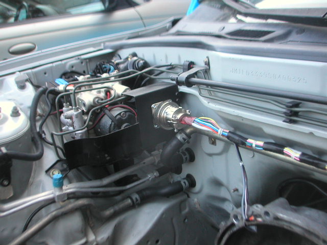
take a look in the corner by the ABS...big blingin nickel coated engine control connector 
ECU is in the stock location...behind the kick panel; passenger side
it probably totals out to be a $400 connector...but I have P/N's if you want them.
https://www.rx7club.com/3rd-generation-specific-1993-2002-16/electron-manipulation-336924/
ECU is in the stock location...behind the kick panel; passenger side
it probably totals out to be a $400 connector...but I have P/N's if you want them.
https://www.rx7club.com/3rd-generation-specific-1993-2002-16/electron-manipulation-336924/
man has anyone told you that you are an electrical bad ***???? Jeez! that is the coolest setup I've seen! I'm seriously thinking of doing that same setup you have because my lt8 was just a dismal failure as far as wiring functionality is conserned. I would love to make the lt10s wiring look stock. I've got an fc but the engine bay on that side is completely empty so I'm sure this could be done pretty easily.......Well as far as space goes it would fit easily is what I should say. Yeah if you have those part numbers I'll price everything and then I'll try to talk myself into doing that. Me and wiring don't get along very well, I've self diagnosted my self as having wiring A.D.H.D
edit: so is the harness attached to the motor itself so that all you have to do is disconnect it at that connector and pull the engine?
edit: so is the harness attached to the motor itself so that all you have to do is disconnect it at that connector and pull the engine?
a quick disconnect wiring harness for pulling a motor... wow.
how long would it take to just disconnect the CAS, TPS, CTS, AIT from the engine? i could disconnect that stuff from my TII in like 5 minutes. seems kinda like a waste of effort to do all that when you could disconnect the few sensors that haltech needs
how long would it take to just disconnect the CAS, TPS, CTS, AIT from the engine? i could disconnect that stuff from my TII in like 5 minutes. seems kinda like a waste of effort to do all that when you could disconnect the few sensors that haltech needs
Thread Starter
development
Joined: Aug 2002
Posts: 5,714
Likes: 7
From: Lafayette, LA
Originally Posted by hondahater
so is the harness attached to the motor itself so that all you have to do is disconnect it at that connector and pull the engine?
So basically, I save the trouble of pulling apart the interior, uplugging the ECU, feeding the boot thru the firewall, and pulling the UIM and vice versa putting the motor back in.
Originally Posted by jacobcartmill
a quick disconnect wiring harness for pulling a motor... wow.
how long would it take to just disconnect the CAS, TPS, CTS, AIT from the engine? i could disconnect that stuff from my TII in like 5 minutes. seems kinda like a waste of effort to do all that when you could disconnect the few sensors that haltech needs
how long would it take to just disconnect the CAS, TPS, CTS, AIT from the engine? i could disconnect that stuff from my TII in like 5 minutes. seems kinda like a waste of effort to do all that when you could disconnect the few sensors that haltech needs
i for one am also interested if you can find the parts list for the quick disconnect, i like the idea alot. awesome work man. please post or PM if you get around to digging it up.
thanks
ryan
thanks
ryan

Thread
Thread Starter
Forum
Replies
Last Post
rx8volks
Canadian Forum
0
Sep 1, 2015 11:02 PM
rx8volks
Canadian Forum
0
Sep 1, 2015 10:46 PM