
"Why is this engine so damn complicated??" Part 2: Emissions controls


"Why is this engine so damn complicated??" Part 2: Emissions controls
If your boss came to you and said, "here, take an engine with some inherent emissions problems and make it meet these new standards. But you can't redesign the basic architecture of the engine, you have to reuse a lot of existing technology, and you can't go over budget." To make things even more complicated, a major foreign market has tougher emissions standards than your country does.
So what would you do? You'd look at the previous emissions control designs, try to simplify or enhance the existing stuff in a few places if possible, and then add whatever extra crap may be needed to meet the standards and stay within budget.
This article how and why Mazda designed some of the complicated and ultimately unreliable emissions control systems. Special attention will be paid to the precat and the airpump, with the airpump's related system called the Air Control Valve (ACV).
Problems and Hurdles
So what emissions problems did the factory engineers have to solve on the FD, either by reusing older designs or developing somewhat new ones?
1. How do we minimize emissions while the catalytic converter warms up?
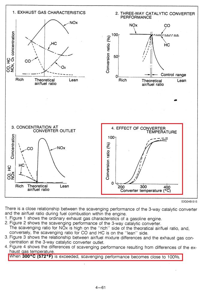
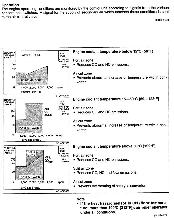
This is often the trickiest emissions hurdle for many engines, and is the reason why many sports cars of that era had so many restrictive catalytic converters (Vr-4 for example). A 3-way catalytic converter (called 3-way in part because it traps 3 different types of emissions) is employed as the main cat on the FD and the older Rx-7 13B's. That's a pretty common architecture used in a most cars now. But a converter has an effective range of operating temperature.
To illustrate the importance of warming up the cat, here is a page out of the 2nd gen service highlights document which explains the operating range on those older models:
Emissions standards are tougher in the US, so Mazda had always needed a cheap way to get the converter up to temperature quickly for only USDM-compliant cars. The Accelerated Warmup System, a valve that brings in extra air to idle the car up to 3000rpm, was employed in older 13B's and carried over to the REW. That system is just a solenoid valve and a simple logic circuit. On a production line, that's not a big deal to implement on some cars and not others. It solved a problem cheaply, but we all know that revving an engine that high when cold can't be good for its longevity.
Still, to keep emissions down while the main cat is still cold, Mazda used two precats on the older engines (both USDM and JDM). They appear to be the same basic design as the main cat, but they are designed to only work as the engine is starting up.

The old precats didn't last forever, but they definitely outlasted the FD's single precat. But why is that?
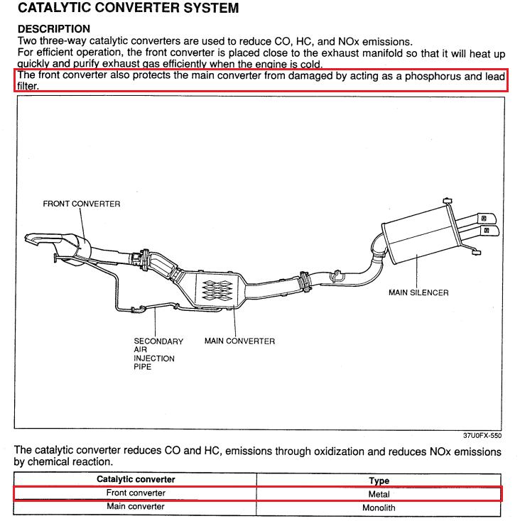
Now I'm no expert on catalytic converters, but a quick google search reveals that "monolith" is a standard design for a converter. Whatever "metal" is, it's different that most stuff out there, and it's different than the old precats. But here's the killer: the precat was designed as a filter. And what do filters do? They pick up particles. The more effective they are at picking up particles, the faster they clog up, generally speaking. Get it?
The problem with the stock FD precat is that it worked too well! Here is one of those situations where I think Mazda meant well, and could have chosen a more reliable/durable design but didn't because they felt they wanted to maximize the performance (as in, the emissions reduction capability) of the component. It's the same deal with the interior. They put performance (weight savings in that case) over usable life--and we pay the price.
Many modern diesel engines (like the latest generation of Ford diesel V8's) are dealing with this type of problem with emissions equipment as their particulate filters clog up prematurely.
So what would you do? You'd look at the previous emissions control designs, try to simplify or enhance the existing stuff in a few places if possible, and then add whatever extra crap may be needed to meet the standards and stay within budget.
This article how and why Mazda designed some of the complicated and ultimately unreliable emissions control systems. Special attention will be paid to the precat and the airpump, with the airpump's related system called the Air Control Valve (ACV).
Problems and Hurdles
So what emissions problems did the factory engineers have to solve on the FD, either by reusing older designs or developing somewhat new ones?
1. How do we minimize emissions while the catalytic converter warms up?
This is often the trickiest emissions hurdle for many engines, and is the reason why many sports cars of that era had so many restrictive catalytic converters (Vr-4 for example). A 3-way catalytic converter (called 3-way in part because it traps 3 different types of emissions) is employed as the main cat on the FD and the older Rx-7 13B's. That's a pretty common architecture used in a most cars now. But a converter has an effective range of operating temperature.
To illustrate the importance of warming up the cat, here is a page out of the 2nd gen service highlights document which explains the operating range on those older models:
Emissions standards are tougher in the US, so Mazda had always needed a cheap way to get the converter up to temperature quickly for only USDM-compliant cars. The Accelerated Warmup System, a valve that brings in extra air to idle the car up to 3000rpm, was employed in older 13B's and carried over to the REW. That system is just a solenoid valve and a simple logic circuit. On a production line, that's not a big deal to implement on some cars and not others. It solved a problem cheaply, but we all know that revving an engine that high when cold can't be good for its longevity.
Still, to keep emissions down while the main cat is still cold, Mazda used two precats on the older engines (both USDM and JDM). They appear to be the same basic design as the main cat, but they are designed to only work as the engine is starting up.
The old precats didn't last forever, but they definitely outlasted the FD's single precat. But why is that?
Now I'm no expert on catalytic converters, but a quick google search reveals that "monolith" is a standard design for a converter. Whatever "metal" is, it's different that most stuff out there, and it's different than the old precats. But here's the killer: the precat was designed as a filter. And what do filters do? They pick up particles. The more effective they are at picking up particles, the faster they clog up, generally speaking. Get it?
The problem with the stock FD precat is that it worked too well! Here is one of those situations where I think Mazda meant well, and could have chosen a more reliable/durable design but didn't because they felt they wanted to maximize the performance (as in, the emissions reduction capability) of the component. It's the same deal with the interior. They put performance (weight savings in that case) over usable life--and we pay the price.
Many modern diesel engines (like the latest generation of Ford diesel V8's) are dealing with this type of problem with emissions equipment as their particulate filters clog up prematurely.
2. How do we keep the catalytic converter running at optimal efficiency, given the unusual characteristics of the rotary engine?
The peripheral exhaust port rotary (13B-REW and earlier) likes to idle or otherwise run richer than gas piston engines in a lot of the low-load operational range. After that rich mixture combusts it needs to be diluted with fresh air (leaned out) so that the catalytic converter can operate near the 14.7:1 AFR range where it is most efficient.
The air pump usually pumps air right into the exhaust port area ("port air" in Mazda's terminology) and before the factory narrowband oxygen sensor. That oxygen sensor tells the computer if the mixture that is about to enter the cat is richer than 14.7:1 , leaner than 14.7:1, or right at 14.7:1 , but isn't completely precise (the Rx-8 uses a factory wideband before the cat). Under some conditions (usually on the highway with medium throttle position) the air pump will put air directly into the cat to reduce NOx emissions. It's not that important to know how all that works.
3. How do we direct the air form the airpump into the exhaust ports or catalytic converter, while keeping the cat in its proper operational range of temperature and AFR?
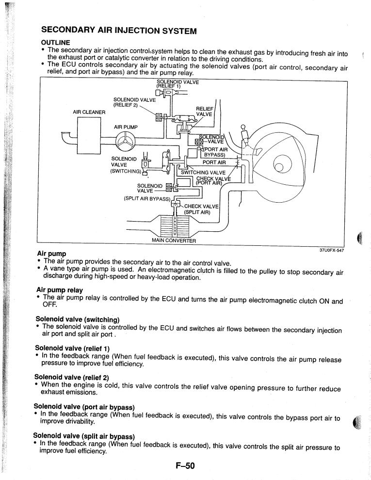
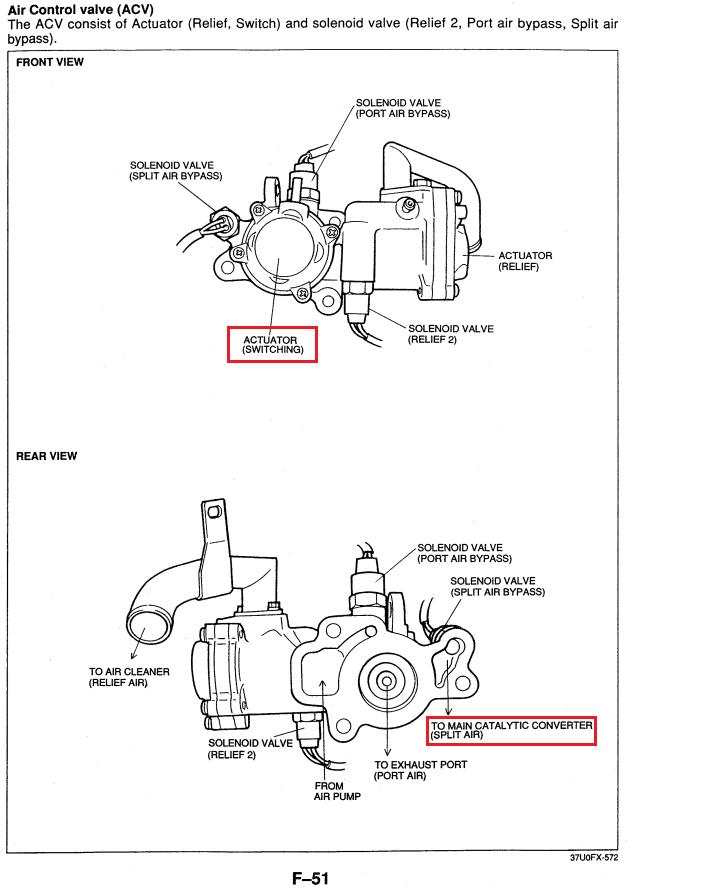
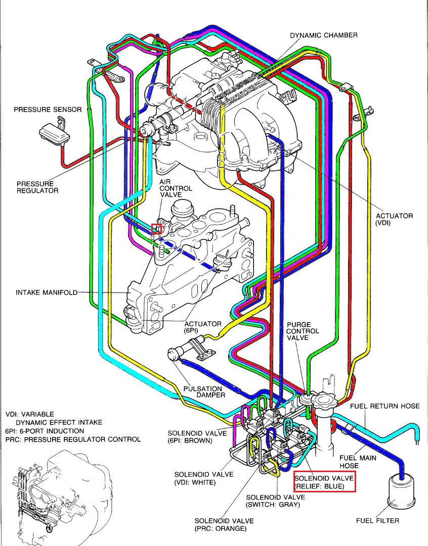
That's where the "ACV" or Air Control Valve comes in. It is a series of mechanical valves controlled by solenoids. Some of those solenoids are on the ACV itself and some are located in the rats nets/solenoid rack. The ACV directs air through passageways in the engine to either the exhaust ports or out to the catalytic converter via the split-air pipe.
Here is a diagram of a 2nd gen ACV. It's basic principles are the same as the FD ACV, except the FD ACV does not have the "anti afterburn" valve.

The FD's airpump is a little more sophisticated, and that means even more rats' nest crap. The purpose of all these valves is to
1) send air to either the exhaust ports or converter
2) disengage sending air to the exhaust ports or converter, for emissions purposes or to preserve the cat.
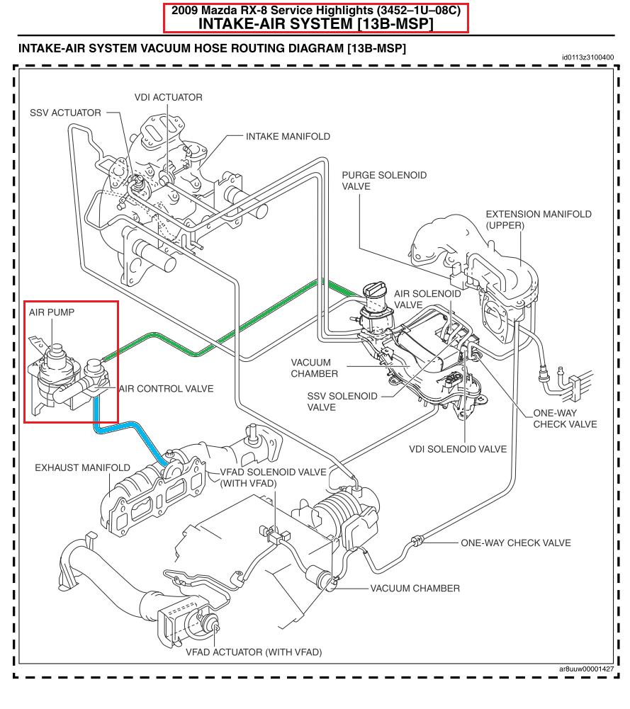
Note that Mazda drastically simplified the air pump and ACV on the Rx-8, presumably from the relocation of the exhaust ports and through the use of drive-by-wire and other computer controls. They also don't have to send air directly to the cat anymore (no split-air pipe), and the pesky precat has been eliminated.
The peripheral exhaust port rotary (13B-REW and earlier) likes to idle or otherwise run richer than gas piston engines in a lot of the low-load operational range. After that rich mixture combusts it needs to be diluted with fresh air (leaned out) so that the catalytic converter can operate near the 14.7:1 AFR range where it is most efficient.
The air pump usually pumps air right into the exhaust port area ("port air" in Mazda's terminology) and before the factory narrowband oxygen sensor. That oxygen sensor tells the computer if the mixture that is about to enter the cat is richer than 14.7:1 , leaner than 14.7:1, or right at 14.7:1 , but isn't completely precise (the Rx-8 uses a factory wideband before the cat). Under some conditions (usually on the highway with medium throttle position) the air pump will put air directly into the cat to reduce NOx emissions. It's not that important to know how all that works.
3. How do we direct the air form the airpump into the exhaust ports or catalytic converter, while keeping the cat in its proper operational range of temperature and AFR?
That's where the "ACV" or Air Control Valve comes in. It is a series of mechanical valves controlled by solenoids. Some of those solenoids are on the ACV itself and some are located in the rats nets/solenoid rack. The ACV directs air through passageways in the engine to either the exhaust ports or out to the catalytic converter via the split-air pipe.
Here is a diagram of a 2nd gen ACV. It's basic principles are the same as the FD ACV, except the FD ACV does not have the "anti afterburn" valve.
The FD's airpump is a little more sophisticated, and that means even more rats' nest crap. The purpose of all these valves is to
1) send air to either the exhaust ports or converter
2) disengage sending air to the exhaust ports or converter, for emissions purposes or to preserve the cat.
Note that Mazda drastically simplified the air pump and ACV on the Rx-8, presumably from the relocation of the exhaust ports and through the use of drive-by-wire and other computer controls. They also don't have to send air directly to the cat anymore (no split-air pipe), and the pesky precat has been eliminated.
Other emissions systems
These systems are commonly employed on piston engines.
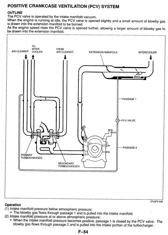
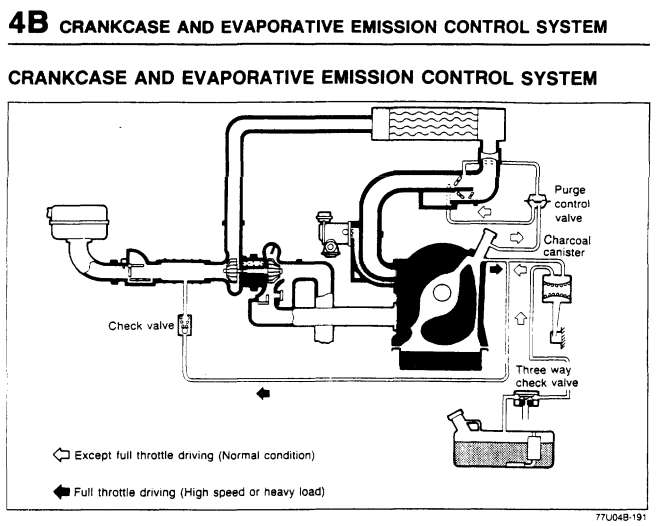
1. Crankcase ventilation--During combustion, there is always going to be some kind of blowby gas or oil. This builds up in the oil pan etc. That gas has to be vented somehow or there will be smoke out the back, especially under load.
There are two ways that these crankcase vapors can leave the engine (through a vent which must be open). They can be drawn out by an external force (manifold vacuum) or they can be pushed out by the internal pressure of the blowby vapors, which will happen by itself under boost/load.
Drawing vapors out under low-load is basically an emissions function. Applying a vacuum to the crankcase is not really "necessary" as long as a vent is open, but in this case Mazda had to apply a vacuum to meet emissions targets. The vapors are drawn out under low load by hooking the crankcase vent to a source of manifold vacuum, and then installing a type of check valve in-line. This check-valve is called a PCV Valve. When the engine is producing a lot of vacuum, especially during deceleration, the PCV valve is open and draws blowby gas back in to the manifold. As manifold vacuum decreases (engine goes into boost/load), the PCV valve will progressively close until it is completely shut.
When the engine is under load then the internal crankcase pressure will force oil and vapors out. This is then routed to before the turbos.
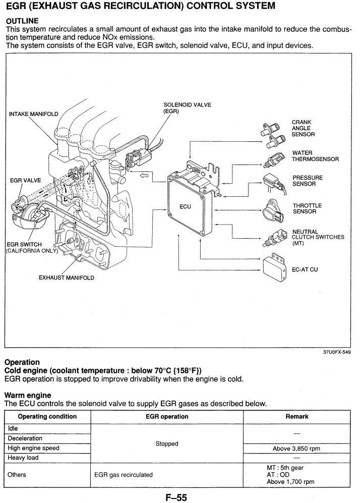
EGR System
EGR, or Exhaust Gas Recirculation, sends air from the exhaust ports back into the intake manifold. The point is to cool the combustion and reduce NOx emissions. Hypothetically it reduces the chance of knock as well, but I'm not sure how much that applies here. Mazda managed to eliminate EGR in the series 5 Rx-7's but they brought it back on the FD. Maybe emissions standards tightened? The peripheral exhaust port rotary (13B-REW and earlier) already recycles exhaust when some of the exhaust gases mix back in with the intake charge as the ports overlap.
Fuel evaporative emissions control system
On modern cars, this is the system that makes you throw a check engine light when your gas cap is loose. Current cars have very elaborate ways of making sure that no fuel vapors from the tank are escaping. On the FD, fuel vapors from the tank are trapped in the charcoal canister. They are then sent into the engine to be burned up. The purge control solenoid valve is operated by the ECU to send these vapors into the engine at time when it would not affect driveability. Previous rotaries had no solenoid valve for this and not have the ECU controlling it precisely.

Conclusion
While Mazda made a huge mistake in their choice of precat design, the rest of the complex system of emissions to me seems unavoidable at the time. They didn't have the budget to redesign the basic dimensions of the rotary engine as they are doing now with the 16X. They didn't have the affordable technology to implement a mechanically simpler ACV, or to use a drive-by-wire system which could simplify some of these emissions functions.
All of these inherent problems I just listed have been eliminated or significantly alleviated in the Rx-8's, and hopefully should be further simplified with the new 16X engine which will be designed to burn the mixture more completely with less emissions. Look at the vacuum routing diagram for the 2009 Rx-8 that I have in my previous post. I don't see any indication of an EGR or PCV valve at all in the 2009 Service Highlights document. Few of those lines are even for emissions functions, but are rather for the sophisticated intake system. Even though the Rx-8 does not really perform like the FD, the Renesis is far more advanced in many ways.
These systems are commonly employed on piston engines.
1. Crankcase ventilation--During combustion, there is always going to be some kind of blowby gas or oil. This builds up in the oil pan etc. That gas has to be vented somehow or there will be smoke out the back, especially under load.
There are two ways that these crankcase vapors can leave the engine (through a vent which must be open). They can be drawn out by an external force (manifold vacuum) or they can be pushed out by the internal pressure of the blowby vapors, which will happen by itself under boost/load.
Drawing vapors out under low-load is basically an emissions function. Applying a vacuum to the crankcase is not really "necessary" as long as a vent is open, but in this case Mazda had to apply a vacuum to meet emissions targets. The vapors are drawn out under low load by hooking the crankcase vent to a source of manifold vacuum, and then installing a type of check valve in-line. This check-valve is called a PCV Valve. When the engine is producing a lot of vacuum, especially during deceleration, the PCV valve is open and draws blowby gas back in to the manifold. As manifold vacuum decreases (engine goes into boost/load), the PCV valve will progressively close until it is completely shut.
When the engine is under load then the internal crankcase pressure will force oil and vapors out. This is then routed to before the turbos.
EGR System
EGR, or Exhaust Gas Recirculation, sends air from the exhaust ports back into the intake manifold. The point is to cool the combustion and reduce NOx emissions. Hypothetically it reduces the chance of knock as well, but I'm not sure how much that applies here. Mazda managed to eliminate EGR in the series 5 Rx-7's but they brought it back on the FD. Maybe emissions standards tightened? The peripheral exhaust port rotary (13B-REW and earlier) already recycles exhaust when some of the exhaust gases mix back in with the intake charge as the ports overlap.
Fuel evaporative emissions control system
On modern cars, this is the system that makes you throw a check engine light when your gas cap is loose. Current cars have very elaborate ways of making sure that no fuel vapors from the tank are escaping. On the FD, fuel vapors from the tank are trapped in the charcoal canister. They are then sent into the engine to be burned up. The purge control solenoid valve is operated by the ECU to send these vapors into the engine at time when it would not affect driveability. Previous rotaries had no solenoid valve for this and not have the ECU controlling it precisely.
Conclusion
While Mazda made a huge mistake in their choice of precat design, the rest of the complex system of emissions to me seems unavoidable at the time. They didn't have the budget to redesign the basic dimensions of the rotary engine as they are doing now with the 16X. They didn't have the affordable technology to implement a mechanically simpler ACV, or to use a drive-by-wire system which could simplify some of these emissions functions.
All of these inherent problems I just listed have been eliminated or significantly alleviated in the Rx-8's, and hopefully should be further simplified with the new 16X engine which will be designed to burn the mixture more completely with less emissions. Look at the vacuum routing diagram for the 2009 Rx-8 that I have in my previous post. I don't see any indication of an EGR or PCV valve at all in the 2009 Service Highlights document. Few of those lines are even for emissions functions, but are rather for the sophisticated intake system. Even though the Rx-8 does not really perform like the FD, the Renesis is far more advanced in many ways.
Great post man,
It's nice to see people spending time analyzing rotaries like that.
Diesel particulate filters normally trigger regeneration events as soon as they start to clogged. In modern diesel engines you can have many injections per cycle (1 or 2 pre injections to bring the chamber to adequate pressure and temperature and for NVH too, 1 or 2 main injections - the ones for torque and 1 or 2 post injections), during regeneration events, post injection(s) are activated, they literally burn in the exhaust to heat up the particulate filter to make that one active and burn all of the particulate (or soot). This strategies take about 30% of all the ECU c code, so to say the least, they are complicated... And cost fuel too.
Diesel particulate filters normally trigger regeneration events as soon as they start to clogged.
Trending Topics


ARGHX - great breakdown on the emissions systems; many do not appreciate what the integrated system really does / works.
One thing that Mazda had a hard time dealing with is the additional oil being burned during combustion as a result of the OMP and it's related components. The pre-cat and port air injection were integral to the solution. From what I understand the renesis has resolved much of the oil in the combustion issue.
One thing that Mazda had a hard time dealing with is the additional oil being burned during combustion as a result of the OMP and it's related components. The pre-cat and port air injection were integral to the solution. From what I understand the renesis has resolved much of the oil in the combustion issue.
the Renesis solved the "oil in the combustion issue" by reducing the oil pressure and not having a center oil injector lubricating the apex seal. Which is why 2004-2008 Renesis engines typically last as long as REW's unless you premix. Series II Rx-8's (09+)have six oil injectors (2 for the side seals, one for the middle of the apex seal), an oil metering pump that functions a bit like a returnless fuel system, and oil pressures back to REW levels.

You could try looking up on these forums what kind of standards people have had to meet in various US states (especially California). That might give you some ballpark.
Now, the emissions output of stock car depends whether it is USDM California spec, USDM Federal spec, or JDM spec.
-- USDM Cali Spec -- EGR, EGR switch, ECU optimized for Cali emissions, Accelerated Warmup System, precat
-- USDM Fed Spec -- Accelerated Warmup System, precat, EGR
-- J spec -- none of the above... I'm pretty sure JDM cars don't even have EGR.
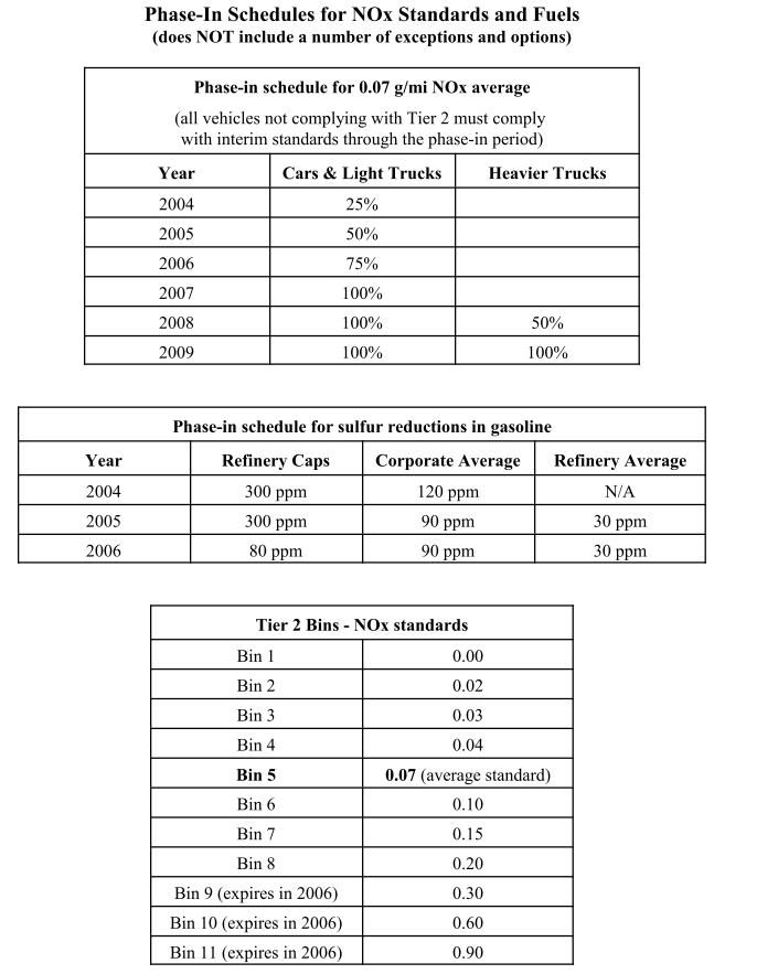
The USDM series 6 cars were in the emissions stone age, and the JDM cars were worse. "Tier 1" USDM emission were introduced in 1996, along with OBD II. The FD couldn't meet them and Mazda stop exporting the car here. The manual tranny Supra couldn't meet the standards in 96, so only automatics were imported for that year. The 300zx Twin Turbo passed the standards but it was detuned from 300 to 280 horse. Tier 2 standards began in 1999, and over time they have tightened progressively to lower and lower "bins." The lower the "bin" number the less emissions, and you get a different designation like "Super low emissions" and "ultra low emissions." You've probably seen stickers for those designations on newer cars.
Now, the emissions output of stock car depends whether it is USDM California spec, USDM Federal spec, or JDM spec.
-- USDM Cali Spec -- EGR, EGR switch, ECU optimized for Cali emissions, Accelerated Warmup System, precat
-- USDM Fed Spec -- Accelerated Warmup System, precat, EGR
-- J spec -- none of the above... I'm pretty sure JDM cars don't even have EGR.
The USDM series 6 cars were in the emissions stone age, and the JDM cars were worse. "Tier 1" USDM emission were introduced in 1996, along with OBD II. The FD couldn't meet them and Mazda stop exporting the car here. The manual tranny Supra couldn't meet the standards in 96, so only automatics were imported for that year. The 300zx Twin Turbo passed the standards but it was detuned from 300 to 280 horse. Tier 2 standards began in 1999, and over time they have tightened progressively to lower and lower "bins." The lower the "bin" number the less emissions, and you get a different designation like "Super low emissions" and "ultra low emissions." You've probably seen stickers for those designations on newer cars.
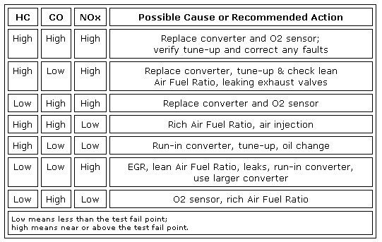
Here's something from the 2nd gen section FAQ. I think the chart is kind of generic, not rotary specific.
My car is having trouble passing emissions, but I have new spark plugs, filters, cats, etc. What do I do?
J-rats Recipe for cheating emissions if its ABSOLUTELY necessary
1. Turn variable resistor to full lean, or as lean as you can get and still run.
2. Trick ACV into pumping air to the cat all the time by removing the FORWARD UPPER vac hose, and capping it.
3. Run 87 octane
4. Run your tank down till your almost empty.
5. 2-3 bottles of alcohol in the tank. Drive VERY GINGERLY to the emissions station.
6. Once you pass go, DIRECTLY to a gas station and fill up with regular unleaded.
That's for a 2nd gen. The variable resistor he is referring to is a screw that sets the idle mixture on series 4 cars. On an FD you can lean out the idle with whatever engine management you have if necessary. For those of you with a PFC who do not have O2 feedback enabled, you can go into the settings-->INJ map and reduce the values in the idle area, which is approximately N2-N3 , P3-P6 .
2. Trick ACV into pumping air to the cat all the time by removing the FORWARD UPPER vac hose, and capping it.

On a series 5 non turbo the switching valve vacuum line is here, in the red box:
That's the "forward upper" hose on the FC ACV that was originally listed. I posted that diagram because the s5 diagram is a lot less overwhelming than the s6. On the s6, it is here:

How the ACV Vacuum Lines and Solenoids work
As I started describing earlier, the switching and relief valves are operated by vacuum actuators. The switching valve directs air to either the exhaust ports (port air) or the cat (split air). With no vacuum applied to the actuator, the passage for port air is closed and the split air passage is open. When vacuum is applied to the switching actuator, the split air passageway closes and air flows to the exhaust ports.
The switching solenoid is, functionally speaking, an NO valve (Normally Open). When the switching solenoid is disengaged, vacuum flows to the switching actuator, and air is directed to the exhaust ports. When the switching valve is engaged (ECU applies ground to the coil), vacuum to the switching actuator is cut. With no vacuum applied to the switching actuator, air pump air is directed to the split air pipe and out to the cat.
The relief valve is just like a blowoff valve for the air pump. It relieves air injection pressure right before the air pump is de-clutched. The air pump is de-clutched for how speed operation and when the exhaust overheat warning comes on. The relief solenoid is an NC (Normally Closed) solenoid functionally equivalent to the charge control solenoid. When air injection pressure needs to be relieved (before de-clutching the air pump), the ECU switches a ground on the relief solenoid which allows engine vacuum to work on the relief valve actuator.
The split air bypass, port air bypass, and relief 2 solenoids are built into the ACV and require no vacuum lines. They are like recirculated blowoff valves (or the charge control valve) and are used to crudely control air injection pressure and volume. After looking over it, the ACV architecture is mostly unchanged from the older rotaries. The only thing that's different is the anti afterburn function, which in the FD is performed by ISC valve instead of the ACV like on the 2nd gen cars.
Secondary air injection control strategy:
Few additions for ya -
- The '95 US FD's don't have EGR. Not sure how Mazda got rid of it there. Funny thing is the '86-88 FC's had EGR, the '89-91 cars didn't. JDM FD's didn't have EGR at all, I've verified that first hand.
- The EGR system on the FD is a joke. If you look at the gasket between the EGR valve and the LIM, there is literally a PINHOLE for the exhaust gasses to travel through to the engine. Anyone who has scraped carbon off motor internals knows that passage would clog in record time. I think the Mazda engineers had to put an EGR valve on not for the effect it had on emissions but to check off some box in the federal emissions standards.
- The '96+ JDM ACV's were redesigned. They only had the vacuum lines going to them, the 3 solenoids that are electronically controlled were totally eliminated. You can see the spot in the casting where they were supposed to go - same casting, just less finishing work. Not sure how the ACV works without those built-in solenoids.
- The PCV system was also re-designed on the '95 US FD. The hose going from the oil fill neck to the PCV valve and then to the upper intake manifold was removed and both ports were capped. This left just one hose on the oil fill neck going to the primary turbo inlet duct. This is really all that's needed, not sure if it was just over-engineered originally or they had to check a box that said the car had a PCV valve. I *think* the JDM cars followed the same design, early cars had PCV, later ones didn't. The '95 system works fine - the turbo inlet duct is at atmospheric pressure, and the gasses can vent there to be burned by the engine and scrubbed by the cats, which is how all evaporative emissions must be handled.
Dale
Great post as always, arghx. Nice to see the history of how Mazda did things before the FD.
DaleClark, awesome info as well. Always good to hear about small details and updates like that.
DaleClark, awesome info as well. Always good to hear about small details and updates like that.
Few additions for ya -
- The '95 US FD's don't have EGR. Not sure how Mazda got rid of it there. Funny thing is the '86-88 FC's had EGR, the '89-91 cars didn't. JDM FD's didn't have EGR at all, I've verified that first hand.
- The EGR system on the FD is a joke. If you look at the gasket between the EGR valve and the LIM, there is literally a PINHOLE for the exhaust gasses to travel through to the engine. Anyone who has scraped carbon off motor internals knows that passage would clog in record time. I think the Mazda engineers had to put an EGR valve on not for the effect it had on emissions but to check off some box in the federal emissions standards.
- The '96+ JDM ACV's were redesigned. They only had the vacuum lines going to them, the 3 solenoids that are electronically controlled were totally eliminated. You can see the spot in the casting where they were supposed to go - same casting, just less finishing work. Not sure how the ACV works without those built-in solenoids.
There is precedent for this. The series 3 GSL-SE engines did not have a duty controlled ISC valve. It had a mechanical ISC valve with a vacuum solenoid and a vacuum vent solenoid that were alternately switched on and off to adjust bypass air.
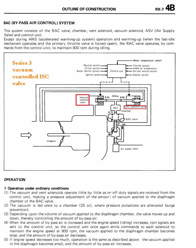
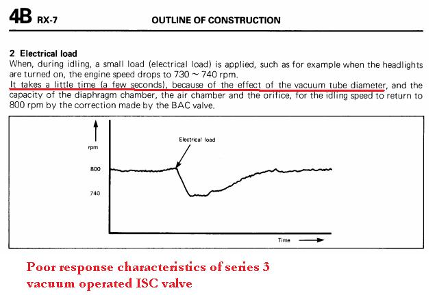
The series 4 FC switched to a duty operated plunger valve that evolved up through series 8. ISC valve design is probably why the FB had a base idle speed of 800, the FC had a base idle speed of 750, and the FD had a base idle speed of 720. Improved ISC design and ignition control allowed the engines to idle stably at a lower base speed.
- The PCV system was also re-designed on the '95 US FD. The hose going from the oil fill neck to the PCV valve and then to the upper intake manifold was removed and both ports were capped. This left just one hose on the oil fill neck going to the primary turbo inlet duct. This is really all that's needed, not sure if it was just over-engineered originally or they had to check a box that said the car had a PCV valve. I *think* the JDM cars followed the same design, early cars had PCV, later ones didn't. The '95 system works fine - the turbo inlet duct is at atmospheric pressure, and the gasses can vent there to be burned by the engine and scrubbed by the cats, which is how all evaporative emissions must be handled.
That's for the 2nd gen turbo cars. The FC did not have an EVAP purge solenoid to precisely meter fuel vapor emissions like the FD. The Rx-8 has an EVAP purge solenoid but also adjusts the drive-by-wire throttle position so that introducing fuel vapors has even less effect on driveability
Do you plan to run the cat for a long time or are you just trying to pass an emissions test so you can pull it back off? Do you have the stock ECU? I see you are in Japan, is this a series 6?

Junior Member
Joined: May 2008
Posts: 23
Likes: 0
From: NAF Atsugi JAPAN
Nah i guess you could say its a series 1? its a efini 92. i went to get the land transportation office LTO inspection and it failed for no air pump. i just put it on and the acv , but got vacuum to both of the acv ports, it passed but i just want to put it on the right way. took out the solenoid rack. I got a sard sports catalyzer.
That's interesting that you applied straight vacuum to both the relief valve and the switching valve and still passed. According to the diagrams, that would send your airpump air right to the exhaust ports (port air) but also bleed air out of the ACV through the relief valve.
If you want to do it "properly" you need to plug in the 3 plugs on the ACV (relief 2, split air bypass, port air bypass), then hook up the switching and relief solenoids to their respective actuators. When the switching solenoid is engaged by the ECU, vacuum is cut from the switching actuator. With vacuum cut, air pump air is directed to the cat instead of to the exhaust ports. When the relief solenoid is engaged, vacuum is supplied to the relief actuator. The relief actuator is like a blowoff valve for the ACV--it usually engages right around the time the airpump is declutched.
Now I haven't examined the switching and relief solenoids closely. Do they have just two ports on them? That's what I would expect.