
"Why is this engine so damn complicated??" Part 2: Emissions controls


Junior Member
Joined: May 2008
Posts: 23
Likes: 0
From: NAF Atsugi JAPAN
they didnt smog check it, they just checked to see if the pump was there. it wont pass smog its running rich with the stock pfc map. i just got rid of all the vacuum lines not needed since i went single turbo.i guess ill get rid of the pcv and double throttle also. maybe the AWS and the heater hose for the butterflies too.


Joined: Mar 2001
Posts: 31,851
Likes: 3,241
From: https://www2.mazda.com/en/100th/
a stock JDM car will pass any of the local smog check tailpipe tests, but it fails the visual because it doesnt have a check engine light.
the 96+ FD's are not OBD2, so they will also fail, there is no ecu to plug into the smog test machine too...
and also the VIN number is weird....
if you are trying to bring the car into the US the DOT and EPA have easy to find and follow rules...

i don't want to know the different standards of EPA CARB or any other smog test agency i just want to find out the C0 NoX and HC Values on different rpms for the 99spec jdm stock model ... i don't really care if this model fails some us smog tests because i need those infos to legalize my car in germany ...
Definitely! I'd like to learn more about the idle control system. You have helped me in this area in other posts but who knows what else there is to learn.
I'm still trying to figure out how I would do an article on the idle control system. I could address Rx-7 stuff specifically but I'd also like to explain comparable systems on other cars, like plunger style coolant controlled fast idle and bimetal fast idle, stepper motors, etc. I'd also like to discuss some of the simplifications/modernizations Mazda did on the FD compared especially to the series 3 FB (which I've already briefly mentioned--the FB was VERY crude). And that's just the mechanical side. On the control side there is all the basic control parameters for different loads but then there is idle ignition control logic, cold start idle ignition advance blah blah blah... it could be a very sprawling type of deal. Sometimes it's hard to explain one system without explaining the context of what other cars were doing at the time. And the FD's idle and TB control systems are pretty much exactly what most of the other manufacturers of that time were using, there's nothing really unique about it.
Air/Fuel Ratios and Emissions Chemisty
There are four major types of emissons produced by an automotive engine (rotary or piston). They are HC, CO, NOx, and CO2. Due to the nature of the combustion process, something undesireable is going to come out of the tailpipe even if it is in small quantities.
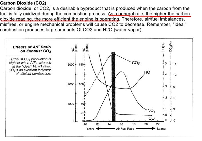
Reducing emissions of one type of gas increases emissions of another. At lean mixtures, NOx is produced. At rich mixtures, NOx is minimized but HC and CO are produced. At the ideal stoichiometric air/fuel ratio, CO2 emissions are maximized. Very few people understand this!
The first type of emission is HC, basically unburnt fuel. Besides the air/fuel ratio, the geometry of the engine plays a big role. When the flame front collides with something, it is extinguished and HC emissions can result.
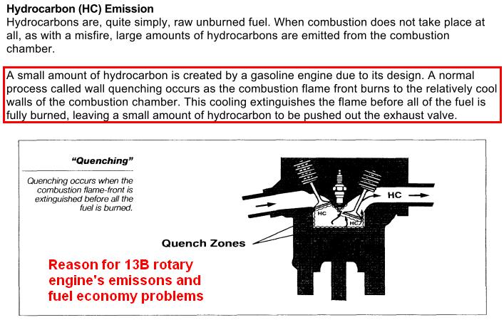
The 13B-REW and 13B-MSP Renesis have a geometry such that the leading and trailing flame fronts collide before they fully reach the side housings (think 3 dimensionally). The experimental 16X Renesis engine has a relatively "thinner" combustion chamber. The leading and trailing plugs are farther apart, so that their individual flames will reach the side housings before they collide with each other, resulting in less "quenching" and unburned fuel. See http://www.rotarynews.com/?q=node/view/1050 and the 16X patent literature http://www.worldcarfans.com/10905261...-rotary-engine
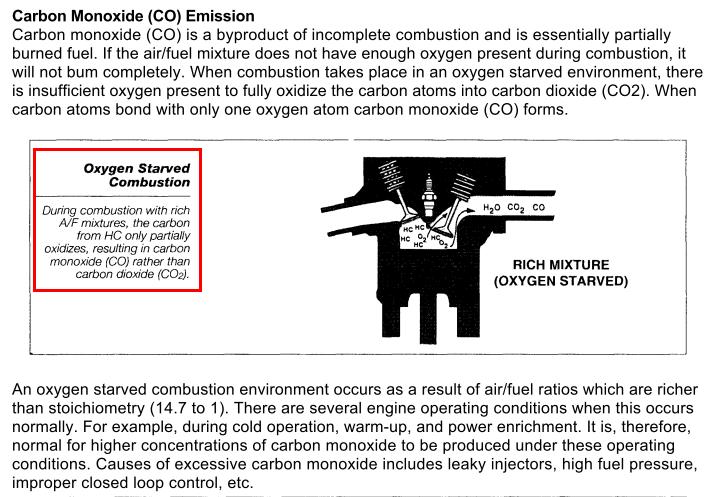
Carbon Monoxide is mostly the result of mixtures richer than 14.7:1
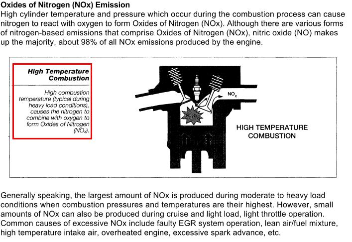
NOx emissions occur when the mixture is too lean or combustion temperatures are too high. That's why manufacturers can't run engines as lean as possible to reduce fuel consumption.
Carbon Dioxide (CO2), the leading greenhouse gas emission, is actually maximized when the catalytic converter is working most efficiently. As counter intuitive as it sounds, the cleanest engines at a particular level of fuel economy actually produce the most greenhouse gas. This explains just how difficult and complicated it can be to control emissions.
these images are sourced from Toyota technician training documents
There are four major types of emissons produced by an automotive engine (rotary or piston). They are HC, CO, NOx, and CO2. Due to the nature of the combustion process, something undesireable is going to come out of the tailpipe even if it is in small quantities.
Reducing emissions of one type of gas increases emissions of another. At lean mixtures, NOx is produced. At rich mixtures, NOx is minimized but HC and CO are produced. At the ideal stoichiometric air/fuel ratio, CO2 emissions are maximized. Very few people understand this!
The first type of emission is HC, basically unburnt fuel. Besides the air/fuel ratio, the geometry of the engine plays a big role. When the flame front collides with something, it is extinguished and HC emissions can result.
The 13B-REW and 13B-MSP Renesis have a geometry such that the leading and trailing flame fronts collide before they fully reach the side housings (think 3 dimensionally). The experimental 16X Renesis engine has a relatively "thinner" combustion chamber. The leading and trailing plugs are farther apart, so that their individual flames will reach the side housings before they collide with each other, resulting in less "quenching" and unburned fuel. See http://www.rotarynews.com/?q=node/view/1050 and the 16X patent literature http://www.worldcarfans.com/10905261...-rotary-engine
Carbon Monoxide is mostly the result of mixtures richer than 14.7:1
NOx emissions occur when the mixture is too lean or combustion temperatures are too high. That's why manufacturers can't run engines as lean as possible to reduce fuel consumption.
Carbon Dioxide (CO2), the leading greenhouse gas emission, is actually maximized when the catalytic converter is working most efficiently. As counter intuitive as it sounds, the cleanest engines at a particular level of fuel economy actually produce the most greenhouse gas. This explains just how difficult and complicated it can be to control emissions.
these images are sourced from Toyota technician training documents
Catalytic Converter Efficiency
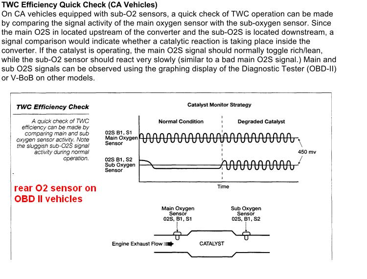
Some of us here may have had narrowband air fuel gauges, or have read O2 sensor readings before. They are not that precise, and they always oscillate from "lean" to "rich." Few realize that catalytic converters are actually designed for this oscillation. In closed loop O2 sensor controlled operation, air/fuel ratios intentionally oscillate around the 14.7:1 AFR. Because lean mixtures produce one type of emission and rich mixtures produce another, two alternating processes are required for clean combustion. Rich mixtures supply gases to catalyze NOx emissions (reduction) while lean mixtures supply gases to catalyze HC and CO emissions (oxidation).Thus it is necessary to alternate between the two conditions.
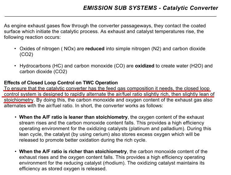
Rear O2 sensors (which are always narrowbands) are used on OBD II vehicles to make sure that the converter is still working. Widebands signals are not depicted here, but on vehicles equipped with factory widebands (Rx-8's, WRX's), the AFR will still oscillate around 14.7:1 but won't deviate as far from that switch point. Wideband O2s allow stock cars to control fuel more precisely during closed loop operation.
Some of us here may have had narrowband air fuel gauges, or have read O2 sensor readings before. They are not that precise, and they always oscillate from "lean" to "rich." Few realize that catalytic converters are actually designed for this oscillation. In closed loop O2 sensor controlled operation, air/fuel ratios intentionally oscillate around the 14.7:1 AFR. Because lean mixtures produce one type of emission and rich mixtures produce another, two alternating processes are required for clean combustion. Rich mixtures supply gases to catalyze NOx emissions (reduction) while lean mixtures supply gases to catalyze HC and CO emissions (oxidation).Thus it is necessary to alternate between the two conditions.
Rear O2 sensors (which are always narrowbands) are used on OBD II vehicles to make sure that the converter is still working. Widebands signals are not depicted here, but on vehicles equipped with factory widebands (Rx-8's, WRX's), the AFR will still oscillate around 14.7:1 but won't deviate as far from that switch point. Wideband O2s allow stock cars to control fuel more precisely during closed loop operation.
That's a good question.
Ceramic vs Metallic Substrate Catalytic Converters
The two questions people usually ask are
1) which flows more?
2) will metallic substrate cats pass emissions tests?
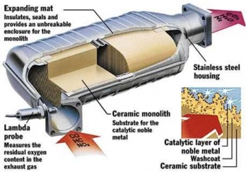
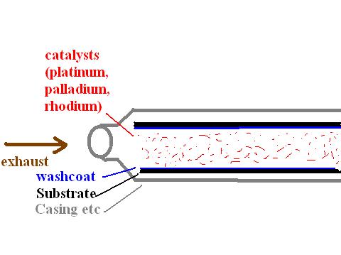
First, remember that what is changing is the substrate (ceramic vs metal), not the catalysts themselves. The substrate is almost like the work bench for the catalyzing process; the process takes place on top of the substrate. The catalysts are still platinum, palladium, and Rhodium with cerium for oxygen storage during the lean portion of the closed loop cycle.
If you take two cats of the same basic dimensions but one of them has a metallic substrate, the one with the metallic substrate will typically flow more and will heat up faster. Note that the factory FD precat has a metallic substrate.
There are a lot of factors that go into the efficiency of the converter, but I'll make it simple. We'll discuss this hypothetically first, to isolate the results from changing only the substrate. If you compare two converters of very similar dimensions and physical shapes on the same engine,
1. the metallic substrate cat may be marginally more efficient at idle for HC, CO, and NOx, at least on paper. But exhaust temperatures, idle AFR, and a lot of different factors really come into play here.
2. the ceramic substrate cat will be more efficient at HC and CO conversion for lower to medium loads and rpm ranges. These are the kind of conditions you may have on an emissions dyno test.
3. the metallic substrate will convert HC and CO better under higher loads and rpms, but these are not likely to be tested at an emissions station.
4. NOx numbers probably won't change much between either type of converter, except perhaps at idle.
Now that's examining the substrate material only. The fact of the matter is, physically smaller converters with less volume will not burn as clean. Conversion efficiency is measured by comparing how much gas is converted vs the amount of exhaust gas per a unit of volume in the cat. This is what's called space velocity:
Space velocity = a constant * [exhaust gas flow / (exhaust molecular weight * catalytic converter volume)]
That's the formula, roughly. And here are some comparison charts:
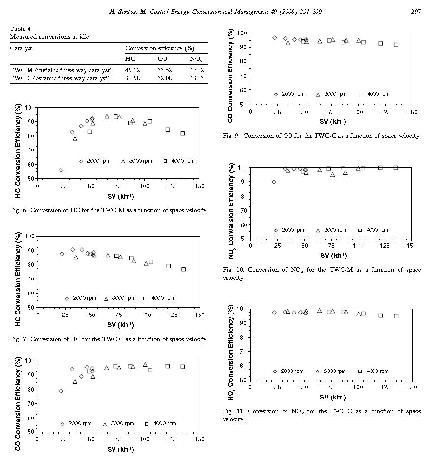
So in conclusion, for aftermarket performance applications a metallic substrate converter will yield at least some improvement in performance compared to a ceramic substrate cat of similar dimensions. This improvement can't be easily quantified because it depends on a number of factors. On OBD 1 cars that need sniffer tests, it may be more difficult to pass with a metallic cat. Rotary engines have enough problems with HC and CO emissions, and metallic cats exacerbate the problem under most driving conditions. This is especially true with performance cats because they are physically a lot smaller (less volume) than OEM units and thus don't work as well to clean up the exhaust. On OBD 2 cars where no actual sniffer tests are involved, there really isn't a downside to using a high quality metallic substrate cat if you are a performance enthusiast.
some images taken from: Santos, "Evaluation of the conversion efficiency of ceramic and metallic three way catalytic converters," Energy Conversion and Management Vol 49 Issue 2, 2008.
Ceramic vs Metallic Substrate Catalytic Converters
The two questions people usually ask are
1) which flows more?
2) will metallic substrate cats pass emissions tests?
First, remember that what is changing is the substrate (ceramic vs metal), not the catalysts themselves. The substrate is almost like the work bench for the catalyzing process; the process takes place on top of the substrate. The catalysts are still platinum, palladium, and Rhodium with cerium for oxygen storage during the lean portion of the closed loop cycle.
If you take two cats of the same basic dimensions but one of them has a metallic substrate, the one with the metallic substrate will typically flow more and will heat up faster. Note that the factory FD precat has a metallic substrate.
There are a lot of factors that go into the efficiency of the converter, but I'll make it simple. We'll discuss this hypothetically first, to isolate the results from changing only the substrate. If you compare two converters of very similar dimensions and physical shapes on the same engine,
1. the metallic substrate cat may be marginally more efficient at idle for HC, CO, and NOx, at least on paper. But exhaust temperatures, idle AFR, and a lot of different factors really come into play here.
2. the ceramic substrate cat will be more efficient at HC and CO conversion for lower to medium loads and rpm ranges. These are the kind of conditions you may have on an emissions dyno test.
3. the metallic substrate will convert HC and CO better under higher loads and rpms, but these are not likely to be tested at an emissions station.
4. NOx numbers probably won't change much between either type of converter, except perhaps at idle.
Now that's examining the substrate material only. The fact of the matter is, physically smaller converters with less volume will not burn as clean. Conversion efficiency is measured by comparing how much gas is converted vs the amount of exhaust gas per a unit of volume in the cat. This is what's called space velocity:
Space velocity = a constant * [exhaust gas flow / (exhaust molecular weight * catalytic converter volume)]
That's the formula, roughly. And here are some comparison charts:
So in conclusion, for aftermarket performance applications a metallic substrate converter will yield at least some improvement in performance compared to a ceramic substrate cat of similar dimensions. This improvement can't be easily quantified because it depends on a number of factors. On OBD 1 cars that need sniffer tests, it may be more difficult to pass with a metallic cat. Rotary engines have enough problems with HC and CO emissions, and metallic cats exacerbate the problem under most driving conditions. This is especially true with performance cats because they are physically a lot smaller (less volume) than OEM units and thus don't work as well to clean up the exhaust. On OBD 2 cars where no actual sniffer tests are involved, there really isn't a downside to using a high quality metallic substrate cat if you are a performance enthusiast.
some images taken from: Santos, "Evaluation of the conversion efficiency of ceramic and metallic three way catalytic converters," Energy Conversion and Management Vol 49 Issue 2, 2008.
+1
To arghx: I just want to take a moment to acknowledge your efforts and contribution to the board. I know how time consuming it is to research and write technical posts that are factual, meaningful and accurate. Your FC notwithstanding, presenting such posts is sufficient to assure that you have no life.
Thanks.

Joined: Jul 2003
Posts: 4,678
Likes: 97
From: Bay Area, CA
So in conclusion, for aftermarket performance applications a metallic substrate converter will yield at least some improvement in performance compared to a ceramic substrate cat of similar dimensions. This improvement can't be easily quantified because it depends on a number of factors. On OBD 1 cars that need sniffer tests, it may be more difficult to pass with a metallic cat. Rotary engines have enough problems with HC and CO emissions, and metallic cats exacerbate the problem under most driving conditions. This is especially true with performance cats because they are physically a lot smaller (less volume) than OEM units and thus don't work as well to clean up the exhaust. On OBD 2 cars where no actual sniffer tests are involved, there really isn't a downside to using a high quality metallic substrate cat if you are a performance enthusiast.
Test________CO2%__O2%______HC(PPM)________CO%_____ ____NO(PPM)______
______RPM_MEAS__MEAS__MAX_AVE_MEAS__MAX__AVE__MEAS _MAX__AVE__MEAS
15mph_1768_14.30__0.80_|_88__21___22__|_0.52__0.06__0.01_|_704__150__167
25mph_2922_14.40__0.50_|_53__13____6__|_0.50__0.05__0.24_|_738__136___87
Test________CO2%__O2%______HC(PPM)________CO%_____ ____NO(PPM)_____
_______RPM_MEAS__MEAS__MAX_AVE_MEAS__MAX__AVE__MEA S_MAX__AVE__MEAS
15mph_1771_14.69__0.16_|_88__21__120__|_0.52__0.06__0.57_|_704__150__245
25mph_2034_14.70__0.11_|_53__13__106__|_0.50__0.05__0.65_|_738__136__201
This was with the stock ECU. I am pretty sure with a little tweaking, it would be possible to pass with a PFC and a metallic cat. Though the PFC turns off the air pump at 2500rpm (the stock ECU turns it off at 3000rpm) so the 25mph part of the test would have to be done in third gear.
I know how time consuming it is to research and write technical posts that are factual, meaningful and accurate. Your FC notwithstanding, presenting such posts is sufficient to assure that you have no life.
FD vs FC precat system
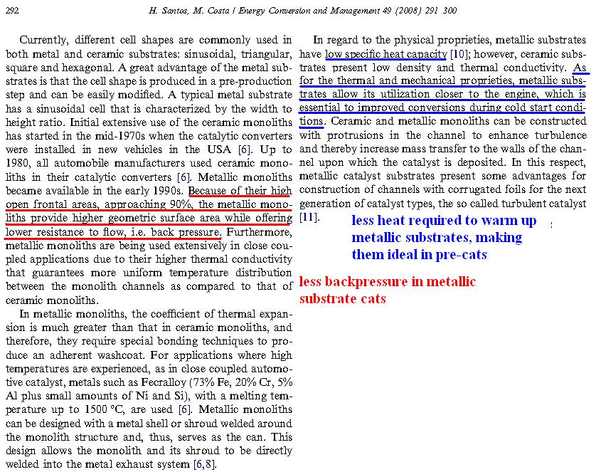
The FD precat had a metallic substrate, which [when the converter is new and not clogged] means better emissions and less backpressure. The USDM-compliant 2nd gen cars used two ceramic substrate precats. During warmup, metallic substrates are better for emissions because it takes less heat to get them to operating temperature (lower specific heat). Once the car reaches operating temperatures, metallic substrates are better for flow but worse for HC and CO emissions.
FD:
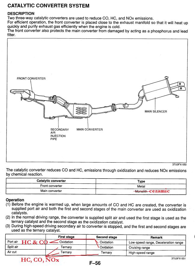
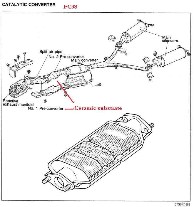
During conditions that produce high levels of HC and CO (idle and warmup), the ACV directs airpump air to the exhaust ports (before the O2 sensor) by using the port air solenoid and actuator. During port air conditions the main converter is used exclusively for oxidation (HC and CO conversion). For whatever reason, the FD metal precat clogged very quickly compared to the FC3S dual ceramic precat design. The Rx-8 Renesis engines are sufficiently cleaner that both the precat and split air pipe were eliminated altogether, although the air pump remains and still supplies port air.
The FD precat had a metallic substrate, which [when the converter is new and not clogged] means better emissions and less backpressure. The USDM-compliant 2nd gen cars used two ceramic substrate precats. During warmup, metallic substrates are better for emissions because it takes less heat to get them to operating temperature (lower specific heat). Once the car reaches operating temperatures, metallic substrates are better for flow but worse for HC and CO emissions.
FD:
During conditions that produce high levels of HC and CO (idle and warmup), the ACV directs airpump air to the exhaust ports (before the O2 sensor) by using the port air solenoid and actuator. During port air conditions the main converter is used exclusively for oxidation (HC and CO conversion). For whatever reason, the FD metal precat clogged very quickly compared to the FC3S dual ceramic precat design. The Rx-8 Renesis engines are sufficiently cleaner that both the precat and split air pipe were eliminated altogether, although the air pump remains and still supplies port air.
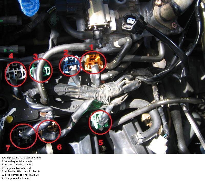
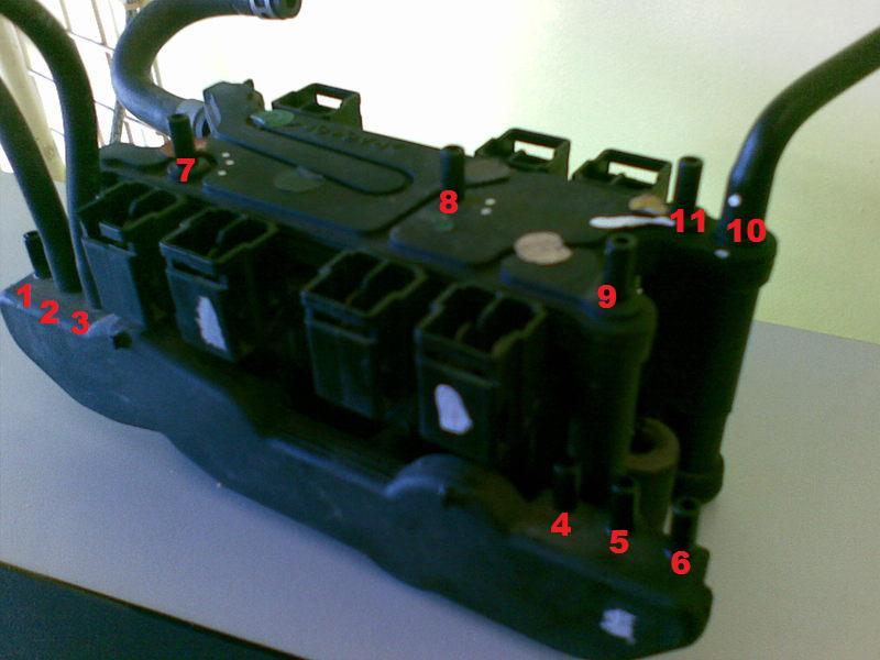
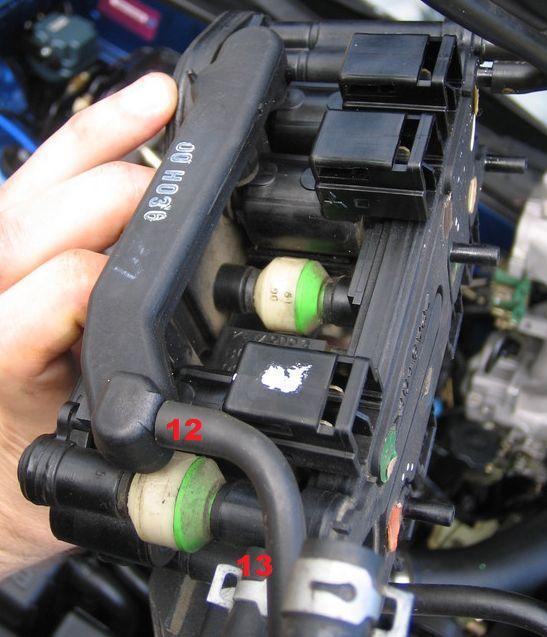
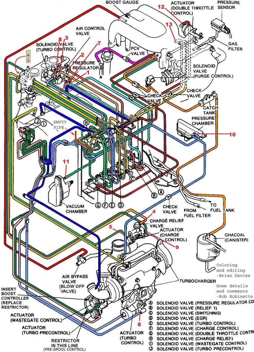
this post is AWESOME!! but i have to be the jerk-off that has to ask the question, would you happen to have the vacuum routing for the rat's nest on the 96 and newer FDs?
Originally Posted by arghx
the ACV directs airpump air to the exhaust ports (before the O2 sensor) by using the port air solenoid and actuator.
Originally Posted by nipponichi_2000
would you happen to have the vacuum routing for the rat's nest on the 96 and newer FDs?
I'm not sure who originally did this, but these pictures and diagrams are supposed to be for series 7 and series 8 cars. I can't really answer any questions on them. I've never even seen a series 7 car in person.
I have no idea if routing changed between series 7 and series 8.
I have no idea if routing changed between series 7 and series 8.
minor correction here. On series 6 the ACV delivers air to the exhaust ports by using the switching vacuum solenoid and actuator, with the port air bypass solenoid to control the pressure.
I've got something on my computer at home that I found on these forums a while back. I'll try to post it up later. Are you Japanese? How come there are very few Japanese people on this board, given how many FD's there must still be in Japan? No offense intended, but I honestly would've expected there to be at least a few Japanese guys on here who have extensive knoweldge of the series 7 and 8 cars. And it's not like there is a huge language barrier since a lot of countries teach English in school.
I've got something on my computer at home that I found on these forums a while back. I'll try to post it up later. Are you Japanese? How come there are very few Japanese people on this board, given how many FD's there must still be in Japan? No offense intended, but I honestly would've expected there to be at least a few Japanese guys on here who have extensive knoweldge of the series 7 and 8 cars. And it's not like there is a huge language barrier since a lot of countries teach English in school.
thanks for the pics. that is the same block i have. its just that someone else took this engine apart and now i have to piece it all back together and this is what i've came too.
I originally posted this on the Rx-8 forums, but most of us here are driving an OBD II car every day. 2001+ models have stricter standards for OBD II readiness.
OBD II Inspection Readiness
I think there's a lot of confusion floating around about what inspection "readiness" really means.
Here's how it works. OBD II was designed to make tailpipe testing unnecessary. Therefore the PCM tests the emissions control systems on its own. The ECU can't always take a "snapshot" of sensor data to know whether a system is working right. It takes time and certain types of driving conditions to know for sure.
The most common/important tests that need to be flagged "Ready" are:
-- Catalytic Converter test: the PCM monitors rear O2 sensor voltage over time to see if your cat is working right
-- Evaporative system: the test that makes you throw a code when the gas cap is loose. EVAP systems are actually crazy complicated.
-- Oxygen sensor: the PCM checks for a particular signal curve over time. The exact test depends on the sensor's position (Front or rear) and whether it is a wide or narrowband sensor. There's also tests for the the O2 sensor heater.
-- EGR system: not many newer cars have this, but you will find it on a lot of early OBD II cars (late 90s).
After you disconnect the battery or clear codes, most of the readiness monitors go to "Not ready."
It is a myth that you need to drive x miles for the car to be "ready" for inspection. There's no set number of miles. I've passed inspections after less than 50 miles of driving sometimes. It just depends.
The Do-It-Yourself OBD II Inspection
The best way to determine whether your car is ready for inspection is to hook up to a higher end OBD II scanner if you have one. I have one of the big orange Actron scanners (Actron CP9180) that you usually see being used by auto parts store employees. It was maybe $120 new off ebay when I bought it a while ago.
Now I'm going to demonstrate me checking to see if my car will pass inspection. This is my daily driver, a 1997 Infiniti Q45. My 1988 Rx-7 Turbo doesn't even have a check engine light!
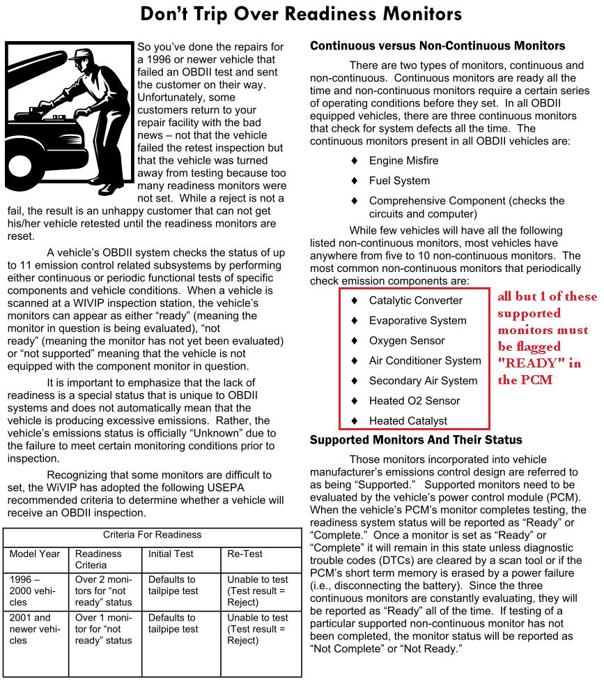
The first shot here is of the main menu in the Actron CP9180. I have two choices. I can select "State OBD Check" to get a summary of my readiness monitors and DTC's. I can also select "I/M Monitors" to get a breakdown of all the readiness checks in the PCM. So first I select "State OBD Check."
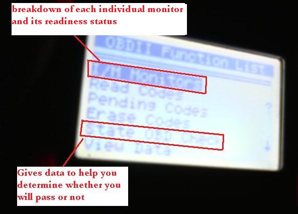
From this screen I can see that the check engine light (Malfunction Indicator Light) is not active. I do have one DTC however, but it is a "pending" code that has not yet tripped the MIL. This number could be "3" if I had two active codes and one pending code.
Then the scantool separates my readiness monitors into 3 categores: OK, Incomplete, or Not Applicable. Any 2001+ car must have all but 1 supported monitor set as "OK." Only 1 readiness monitor can be set flagged as "incomplete." This car will pass an inspection because the MIL has not been set and all monitors are ready. Now let's take a more detailed look at my list of readiness monitors in the "I/M Monitors" screen.
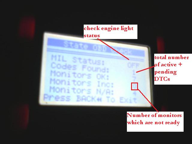
Those top three are my continuous monitors. Those three are always active. Any monitor that is not supported is listed as N/A. This particular car has an EGR readiness monitor but it does not have an EVAP monitor.
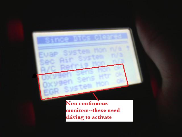
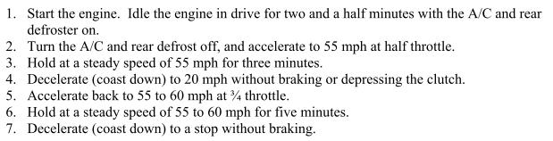
Any monitor that requires some sort of drive cycle is called a non-continuous monitor. Those are the ones you are waiting on when you visit the inspection station. In my experience the Catalyst monitor and the EVAP monitors take the longest to be set. Here is a drive cycle that may help set the monitors:
I hope that clears up some confusion about OBD II inspections and "readiness" tests. Engines don't just arbitrarily become "Ready" after x number of miles or x number of drive cycles. PCM's go through a series of tests to make sure the components are working, and different criteria must be met for every engine. A lot of inspectors really don't understand this system fully. They just do whatever their inspection tool tells them.
OBD II Inspection Readiness
I think there's a lot of confusion floating around about what inspection "readiness" really means.
Here's how it works. OBD II was designed to make tailpipe testing unnecessary. Therefore the PCM tests the emissions control systems on its own. The ECU can't always take a "snapshot" of sensor data to know whether a system is working right. It takes time and certain types of driving conditions to know for sure.
The most common/important tests that need to be flagged "Ready" are:
-- Catalytic Converter test: the PCM monitors rear O2 sensor voltage over time to see if your cat is working right
-- Evaporative system: the test that makes you throw a code when the gas cap is loose. EVAP systems are actually crazy complicated.
-- Oxygen sensor: the PCM checks for a particular signal curve over time. The exact test depends on the sensor's position (Front or rear) and whether it is a wide or narrowband sensor. There's also tests for the the O2 sensor heater.
-- EGR system: not many newer cars have this, but you will find it on a lot of early OBD II cars (late 90s).
After you disconnect the battery or clear codes, most of the readiness monitors go to "Not ready."
It is a myth that you need to drive x miles for the car to be "ready" for inspection. There's no set number of miles. I've passed inspections after less than 50 miles of driving sometimes. It just depends.
The Do-It-Yourself OBD II Inspection
The best way to determine whether your car is ready for inspection is to hook up to a higher end OBD II scanner if you have one. I have one of the big orange Actron scanners (Actron CP9180) that you usually see being used by auto parts store employees. It was maybe $120 new off ebay when I bought it a while ago.
Now I'm going to demonstrate me checking to see if my car will pass inspection. This is my daily driver, a 1997 Infiniti Q45. My 1988 Rx-7 Turbo doesn't even have a check engine light!
The first shot here is of the main menu in the Actron CP9180. I have two choices. I can select "State OBD Check" to get a summary of my readiness monitors and DTC's. I can also select "I/M Monitors" to get a breakdown of all the readiness checks in the PCM. So first I select "State OBD Check."
From this screen I can see that the check engine light (Malfunction Indicator Light) is not active. I do have one DTC however, but it is a "pending" code that has not yet tripped the MIL. This number could be "3" if I had two active codes and one pending code.
Then the scantool separates my readiness monitors into 3 categores: OK, Incomplete, or Not Applicable. Any 2001+ car must have all but 1 supported monitor set as "OK." Only 1 readiness monitor can be set flagged as "incomplete." This car will pass an inspection because the MIL has not been set and all monitors are ready. Now let's take a more detailed look at my list of readiness monitors in the "I/M Monitors" screen.
Those top three are my continuous monitors. Those three are always active. Any monitor that is not supported is listed as N/A. This particular car has an EGR readiness monitor but it does not have an EVAP monitor.
Any monitor that requires some sort of drive cycle is called a non-continuous monitor. Those are the ones you are waiting on when you visit the inspection station. In my experience the Catalyst monitor and the EVAP monitors take the longest to be set. Here is a drive cycle that may help set the monitors:
I hope that clears up some confusion about OBD II inspections and "readiness" tests. Engines don't just arbitrarily become "Ready" after x number of miles or x number of drive cycles. PCM's go through a series of tests to make sure the components are working, and different criteria must be met for every engine. A lot of inspectors really don't understand this system fully. They just do whatever their inspection tool tells them.

93 does not get a signal to keep the air pump on
Hi Arghx,
First let me thank you for a great article.
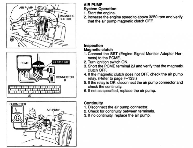
I am praying that you can shed some light on the de-clutching of the air pump itself. I purchased a 93 with no modifications to the emissions system except for the removal of the precat, (it has a downpipe). Currently the air pump will only come on momentarily when the car is first started, and then it immediately is told to shut off. If I short the air pump relay and force it to run, the car will pass smog here in California with no problem. However, I can not for the life of me figure out what is causing it to not get a signal to stay on below 3250 rpm like it is supposed to.
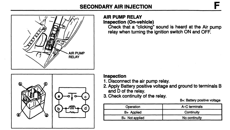
The O2 sensor is fine, the map sensor is fine, the air pump relay is fine, and the air pump itself is fine.
Having read your thread, it sounds like the ACV and its controlled solenoids direct the air, but do not tell the air pump to clutch or de-clutch. Can you tell me what controls the on/off behavior of the air pump itself? And have you already written something about this that I have not seen?
Thanks in advance for any help.
-Coov
First let me thank you for a great article.
I am praying that you can shed some light on the de-clutching of the air pump itself. I purchased a 93 with no modifications to the emissions system except for the removal of the precat, (it has a downpipe). Currently the air pump will only come on momentarily when the car is first started, and then it immediately is told to shut off. If I short the air pump relay and force it to run, the car will pass smog here in California with no problem. However, I can not for the life of me figure out what is causing it to not get a signal to stay on below 3250 rpm like it is supposed to.
The O2 sensor is fine, the map sensor is fine, the air pump relay is fine, and the air pump itself is fine.
Having read your thread, it sounds like the ACV and its controlled solenoids direct the air, but do not tell the air pump to clutch or de-clutch. Can you tell me what controls the on/off behavior of the air pump itself? And have you already written something about this that I have not seen?
Thanks in advance for any help.
-Coov
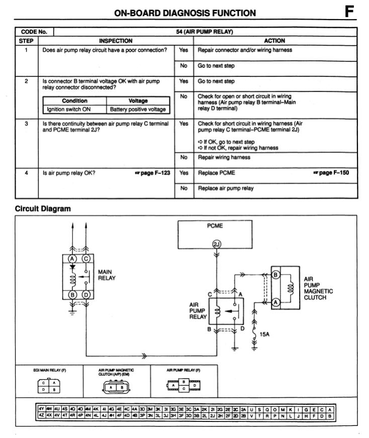
The only information I have seen is from the stock ECU pinout, which indicates that it is controlled based on rpm:
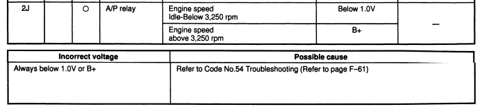
That's all the documentation I could find on the basic control logic. It's possible that there are undocumented parameters affecting its control. We do know that if an airpump relay fault code is triggered, it will disable the output from the ECU to the relay:
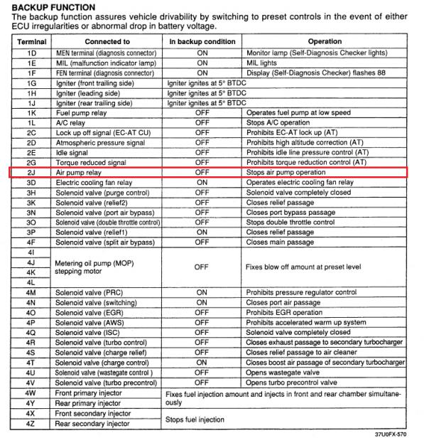
The diagnostic procedures mostly relate to checking the air pump relay, the electrical connection, or the ECU itself.
EDIT: After re-reading your post, it looks like I'm not telling you much that you don't already know. If there's any more information available on the air pump clutch control I've certainly never seen it, and I have collected a lot of information on these cars over the years.
Try swapping the ECU at this point, if you're sure everything else is ok. There are a few out there as far as California vs Federal spec ECUs and such. I'm not sure how much it matters.
That's all the documentation I could find on the basic control logic. It's possible that there are undocumented parameters affecting its control. We do know that if an airpump relay fault code is triggered, it will disable the output from the ECU to the relay:
The diagnostic procedures mostly relate to checking the air pump relay, the electrical connection, or the ECU itself.
EDIT: After re-reading your post, it looks like I'm not telling you much that you don't already know. If there's any more information available on the air pump clutch control I've certainly never seen it, and I have collected a lot of information on these cars over the years.
Try swapping the ECU at this point, if you're sure everything else is ok. There are a few out there as far as California vs Federal spec ECUs and such. I'm not sure how much it matters.
Last edited by arghx; Nov 6, 2011 at 09:56 PM. Reason: re-read your post
Hi Arghx,
Thanks. You are right, most of this I have already went through. However, I am getting a ACV code when I take it down to my local mechanic. With the manifold now removed, I can see the the main switching solenoid in the ACV "rat's nest" is not connected, (the one that feeds the downstream solenoids that send to the cat or the exhaust port).
I have to wait for Monday in order to get a manifold gasket to put the whole thing back together. The solenoid seems to check out. I and my local mechanic are both praying that this is the reason the ECU is telling the air pump clutch not to remain on. Everything else from the relays all the way up to the exhaust overheat system all seem to be functioning correctly.
I am hesitant to say that this is the culprit, since where the air goes should not affect the air pump being turned on, but hopefully it is. My only fallback at this point is to swap the ECU, (I have a Power FC coming out later this week.)
-Coov
You could invert the signal to the air pump relay if you really wanted to. You say that it turns on the relay and then turns it off. Wire up a relay that flips the control logic.
If you are installing a Power FC it will probably solve it. The Power FC doesn't have much in the way of self-diagnosis or fault mode.
If you are installing a Power FC it will probably solve it. The Power FC doesn't have much in the way of self-diagnosis or fault mode.
Hey @arghx and others
I have my ACV off to replace a gasket and just re-read this to better understand how it worked. And also to under why the inside of the ACV is so crusty looking. It looks like it has carbon build up from exhaust.
Reading through this, the ACV gets clean, filtered air from the air pump. The split air to the cat has a check valve so that exhaust theoretically should not be re-introduced to the intake from there.
Is it 'normal' for the inside of the ACV to be 'dirty'?
Thanks.