When you click on links to various merchants on this site and make a purchase, this can result in this site earning a commission. Affiliate programs and affiliations include, but are not limited to, the eBay Partner Network.
I have read some usefull thread about fixing tach, speedo, converting km to miles etc..
I am replacing one capacitor on the usdm spedoometer, so it can work and show the actual miles of the car.
Question: can i swap the usdm speedo to the jdm cluster and expect it to work?
I think it should, but i just want to make sure and not mess up the jdm cluster.
The speedo is a contained unit, as is most of the other parts of the cluster. You can easily mix and match cluster parts. For example, I have a 99 tach and a JDM kPa oil pressure gauge in my US cluster with my US speedo.
Big thing with the speedo is the ribbon cable, make sure to hook it back up, it's easy to forget.
I have read some usefull thread about fixing tach, speedo, converting km to miles etc..
I am replacing one capacitor on the usdm spedoometer, so it can work and show the actual miles of the car.
Question: can i swap the usdm speedo to the jdm cluster and expect it to work?
I think it should, but i just want to make sure and not mess up the jdm cluster.
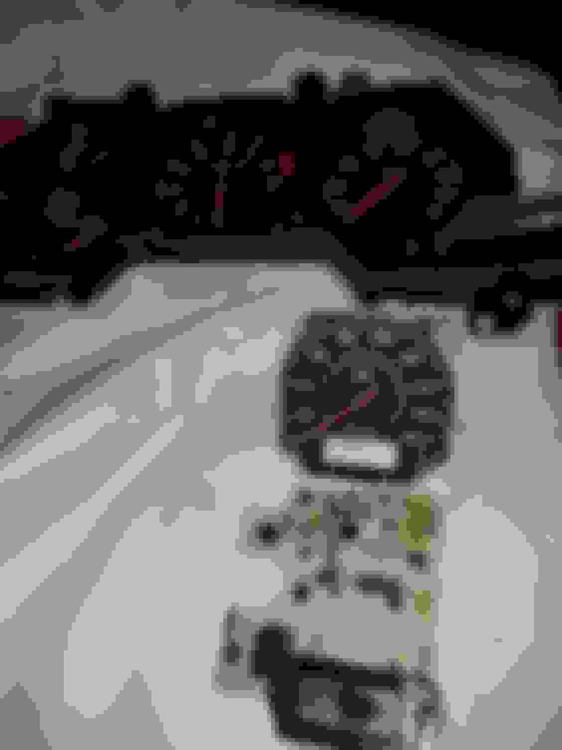
Top=jdm
Thanks in advance,
Red,
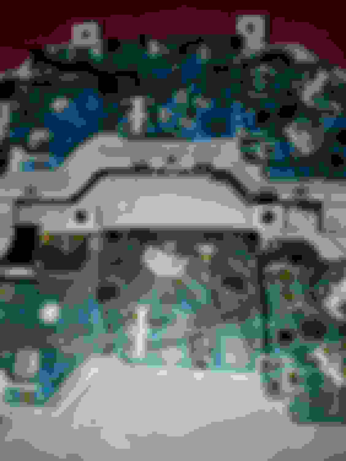
is the odometer display screen damaged? Take a good look at the remaining capacitors on the board since the speedo is removed from it. Take multiple up-close photos of it for reference points later. As a reminder, the negative lead of Capacitor C3 must be soldered to the lower eyelet (closest to DA1). The negative lead is indicated by a long stripe on the cap.
Yep, I don't mind it though. The tach is green and the rest of the gauges are red, but my boost and water temp gauges are green. I think it looks good, it has the "important stuff" in green.
What the hell happened? I swap the odometer to the 99 spec cluster after replacing the capacitor on the odometer to see the milage,. I turned the car on, tach does not work, but i get the molage to display, when the fans came on i had no displayed on my odometer. The tack still doesnt work on the 99 or the old cluster.
Swap the 99 spec tack and odometer to tje old cluster and i have odometer display even with the rad fans on, but no tach.
Any guidence would be appretiated, mean while i am goi ng through a bunch of threds
First, check your METER fuse in the fuse box (by the driver side kick panel). The rad fans run on the same circuit as the instrument cluster. I have an old post (circa 2007) that covers troubleshooting that problem. It can be found here: Blowing Meter Fuse Part 3. Links to the other 2 parts are within that thread.
If the METER fuse is good then remove and reinspect your instrument cluster connections. Did you reconnect the thin ribbon cable from the instrument cluster to the speedometer board? That's the flex print connection shrouded by the black plastic cover. Additionally, ensure that the 4 flex print tabs are bent outwards so they make positive contact with each hard plastic connector from the dash wire harness.
CAUTION: Do not crease the flex print contacts. This may cause a physical break in the thin copper trace and thus create an open circuit.
You may also want to inspect the flex print on the back of the instrument cluster for other potential problems such as creases or melted/burned up copper runs.
Does this give you better insight? Do you have any photos to share? Please keep us posted of your progress!
Yes sir, your information gives me better idea whats going on. The ribon seems to be ok. I think something is making short or open somewhere ☹. The 99 spec tach after a few min its at about 850 rpm, but i know the engine is running 1000 rpm at idle. I givi it some gass and the tach doessnt move.
I will check all what you said and see. I will post some pics too.
thanks for the help.
I still cant make it work.. the meter fuse is fine. The 99 spec speedo works, but no the 99spec tach. I put them both on my old cluster. I put the whole 99 spec cluster and the tach didnt work. I swap parts back and forward and still no tach.
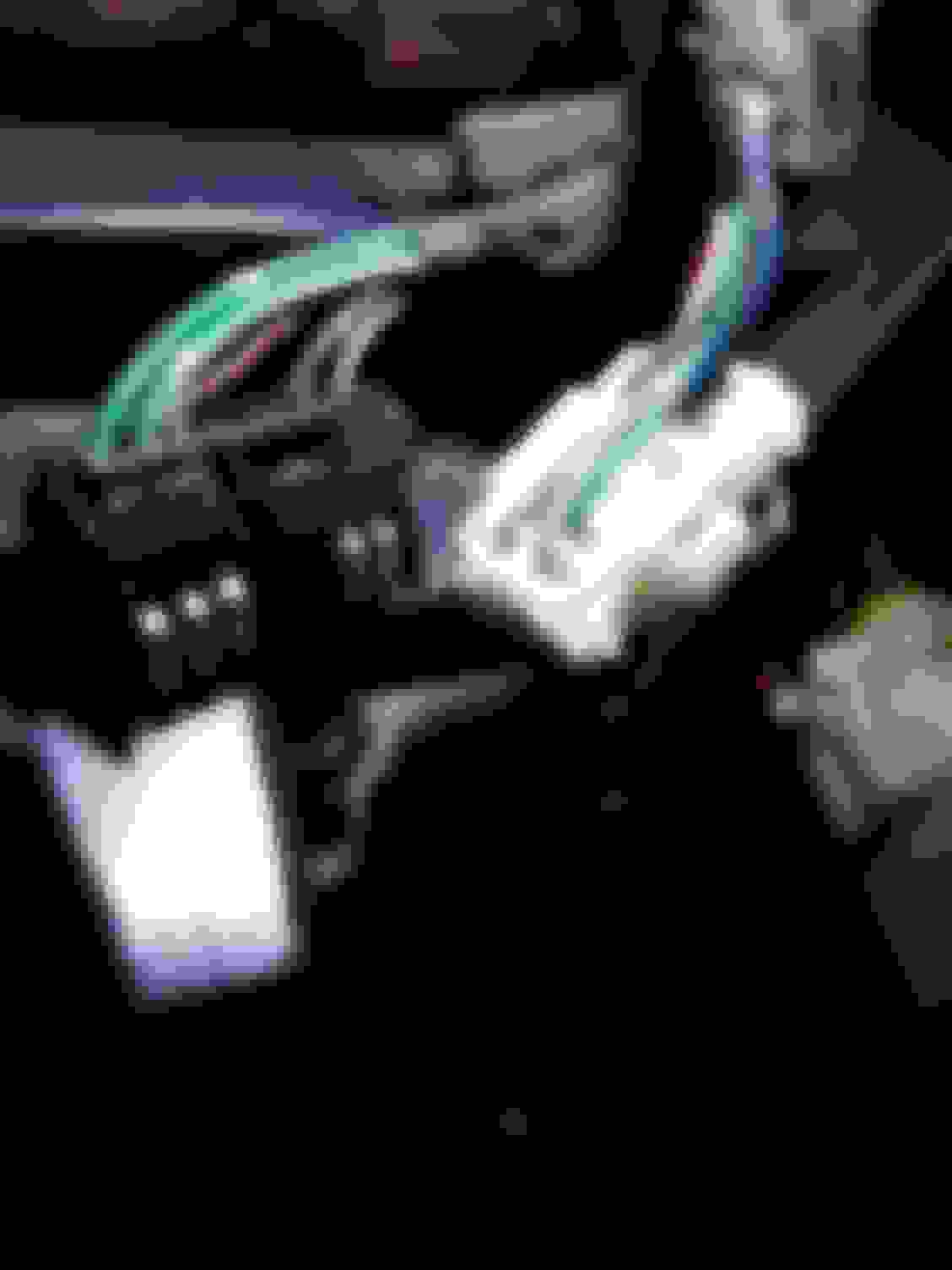
I am trying to take the 12v , ground and tach signal from the wiring plugs to connect them to the tach screws. What wires are for each and what plugs, see pics
Thanks for the feedback on the METER fuse. I recommend not jumping wires to the tach mount screws. It has the potential to cause shorts or burn up the flex print runs elsewhere on the board.
You may have other damaged components on the speedo board. You may have to desolder the Speedo face again then reinspect the board. Also, how does the flex print look that plugs into the speedo board? Do you already have some close-in photos of the speedo board? I may be able to help given the photos.
Could there be any tips or tricks to install the 99 spec tach? It should be plug-and-play. Maybe Dale could offer some tips?
Thanks for the additional photos. I wrote the above reply (Post #18) as you posted them. I have a couple of other recommendations for both clusters.
1. Verify wiring to/from ECU to instrument cluster connectors since the cluster is removed.
2. Use an eraser (top of #2 pencil works fine) to clean all the flex print contacts. Do NOT crease contacts!
3. Clean the contacts with isopropyl alcohol.
4. Apply a thin layer of dielectric grease to the flex print contacts with a cotton swab. To prevent signal shorts, do not wipe dielectric grease across the contact field. Swab along the length of each contact.
5. Bend the flex print contacts outwards (refer to Post #13, especially the CAUTION). The contacts should "interfere" with the hard plastic connector.
6. Follow steps 2 & 3 for each hard plastic connector. This may be more of a challenge depending on the size of the eraser!
7. Reinspect the speedo board flex print pins. Make sure there are no cracks along those traces!
Cheers,
George
Last edited by Gen2n3; Sep 13, 2017 at 08:20 PM.
Reason: Added Item 7
Thanks George, here are some pics of the ribbon. It looks fine. The 99 spec speedo works fine, its just the 99 spec tach that doesnt work. None of the 99 spec components had been meesed with. Dale said that the components are interchangeable.
Thanks again.
This is what i have.
i only care about tach and speedo to work.
The tach stayed at 0 for the first 7 minutes, then went up to litle more than 1k rpm, which is what my comander reads.
The problem : at idle when i give it gas, tje tach doesnt move at all, when i turn tje car off tje tach goes back to 0, as normal.
I seem to remember you have to install an extra ground or power wire to get a 99 spec instrument cluster to work in a 93-95 car. Look at the thread on installing a 99 cluster. Since you are swapping the components into your cluster I don't know if that applies. I seem to remember on a 99 cluster that I got wouldn't do anything until that extra wire was hooked up.
On my car I have a 99 tach but a US speedo in my original cluster housing. I'm not sure if there's anything different with the speedo as far as making that work in an earlier car.
Also, I bought the 99 tach used MANY years ago and just got the tach. Thinking about it, the tach didn't work right - I think it was jumping around. I swapped the tach face onto my tach motor/body (which was a bunch o' work). But, the tach is just 3 wires - power, ground, and input signal. As long as those 3 things are there it should work. It is quite possible that tach is bad - the later clusters typically are less prone to the faults the 93 clusters exhibit but they still can be broken.
Did you take any resistance measurements of the wiring to and from the instrument cluster? How did cleaning the contacts go?
Where do those "pig tail" wires go on the JDM cluster (the ones connected to screws)? What are they connected to? I am unfamiliar with that cluster but I am aware that such JDM clusters must be modified to work in USDM cars. For example, the Oil Pressure gauge on the USDM cluster is replaced by a Boost gauge on the JDM cluster and the wiring on the cluster is different for these gauges.
Could you please restate what components and cluster you are currently using (for my clarification)? Do you have photos of the USDM speedo repair? Close-in photos of the cap and solder joint replacement would be very helpful.
FYI George, the 99 clusters all have that "pigtail" wiring in the back stock. I think they didn't want to re-tool the manufacturing for the changes made in the cluster, it was cheaper just to add that little wiring mod.