When you click on links to various merchants on this site and make a purchase, this can result in this site earning a commission. Affiliate programs and affiliations include, but are not limited to, the eBay Partner Network.
hi guys,
looking at the FSM, 1T is the output for the fuel pump relay. it will provide ground to trigger the relay to give power to the fuel pump. but it also says that it provides +12v when the ignition switch is in the ON position.
shouldn't 1T provide a constant ground even when in ignition ON? if the below is correct, then wouldn't the pump shut itself off when not idling?
Yes. It would shut itself off. That's the whole point-so if the car stalls or there's an accident, the fuel doesn't continue pumping. It works while cranking though. If you just wanted it to run with ignition power, you wouldn't need the ECU to control it, the factory wiring would tap off the ignition power circuit from something like the main relay. And the driver would hear the fuel pump running even with the car off, which is not desirable.
On the 84-88 rotaries (1st gen EFI and 2nd gen) that functionality came from a relay that was connected to the vane airflow meter.
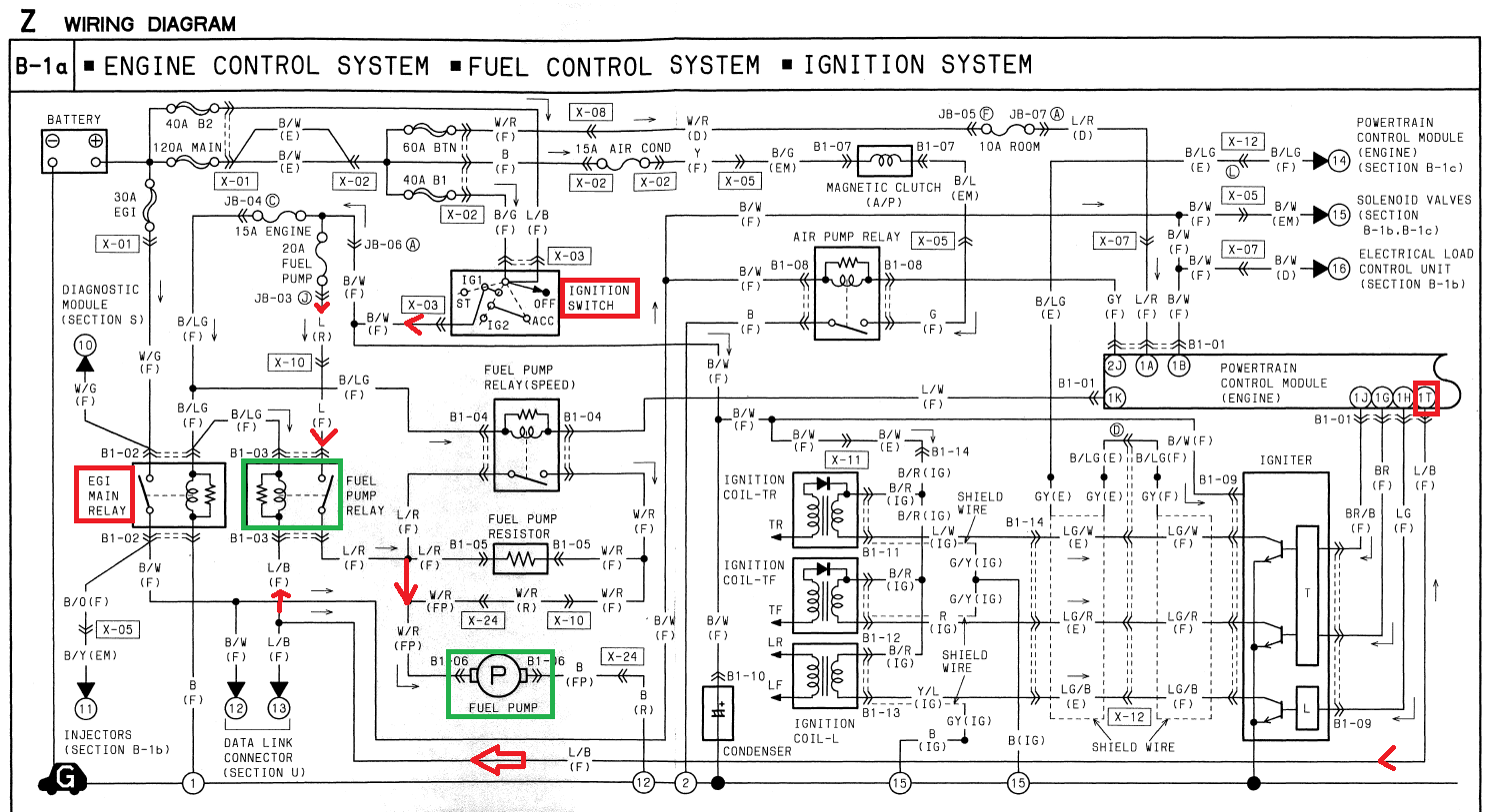
Let's go through the stock wiring diagram from an FD.
Start with the fuel pump, circled in green, and work backwards. On the right you see it runs to ground point #12 (you can dig through the wiring diagrams to find where a particular ground point is). So it's a constant ground. On the left side of pump is the power. The power goes through a resistor to slow the pump down for reducing evaporative emissions, noise, and current draw. That resistor isn't important for performance applications, but it is controlled by a relay that is connected to the stock ECU pin 1K. A "Fuel pump rewire" eliminates this. So if you go through the red arrow I show how the current flows from the fuel pump relay (green) to the pump, if the resistor is bypassed. The power that flows through the fuel pump relay to power the pump comes from the ignition switch, boxed in red. So the fuel pump is already getting ignition switched power. So if it's getting ignition power, what's the point of the fuel pump relay?
The first function of the fuel pump relay is to allow the ECU to control when the pump is to be allowed to run. The ECU judges the running condition and supplies ground to the coil of the fuel pump relay. The power for the fuel pump relay coil is also ignition power, and is tapped in parallel with the main relay. So the fuel pump relay needs ignition switched power and an ECU ground to allow ignition power to flow to the fuel pump.
The second function of the fuel pump relay is to allow a diagnostic function. This bypasses the ECU's running judgment so the fuel system can be pressurized to make fuel system checks. On the 2nd gens (and maybe GSL-SE? don't remember) there is 2-pin connector under the hood to jump for this functionality. On the FD, there is a diagnostic box with a bunch of terminals that can be jumpered. This is called the Data Link Connector in the diagram, and it is tapped in parallel with the ECU pin 1T. So for the fuel pump relay to activate, it needs to receive a ground either from pin 1T or from a ground supplied by the diagnostic box.
On more modern cars like the Rx-8 these functions are controlled over a network bus sending serial commands rather than analog wires physically tripping circuits.
thanks arghx. i did not know that 1T grounds itself when cranking as i have not tested this yet. i was pressurizing my fuel system to make sure there were no leaks.
so let's say the engine fires up while cranking...and then u move the key back to ON position. what tells the ECU to keep grounding 1T to keep the pump running (instead of +12v when ON), would it be that it sees input from the crank position sensors (in my case, the CAS)? just trying to understand things to better help troubleshoot when i get ready to fire up the car for the first time.
whatever the criteria is to judge running that's in the ECU. Usually for a simple judgment it's something like the rpm being greater than say 300. It's going to vary depending on the ECU, but usually there is a series of conditions that are met to judge the engine condition (cold vs warmed up, cranking vs idling, deflood fuel cut condition, etc).
whatever the criteria is to judge running that's in the ECU. Usually for a simple judgment it's something like the rpm being greater than say 300. It's going to vary depending on the ECU, but usually there is a series of conditions that are met to judge the engine condition (cold vs warmed up, cranking vs idling, deflood fuel cut condition, etc).
the service highlights book mentions the RPM number, it is something like 300rpm. there also is a "start" pin, so rpm under 300 and the start pin on = cranking.
i tested the fuel pump while cranking and it was not turning on. i verified and checked all wiring for the fuel pump relay that i had created and all was good. after some further digging, i traced the problem to where i was pulling power for the START position for use by 1C. the connector i was pulling that from had 2 wires of the same color and i grabbed the wrong one. so now fuel pump runs while it cranks.
hi, this is an old thread but i'm having a similar problem and there is good information on here. My problem is that the 1T does not receive a ground signal when the car is cranking therefore never turning on the fuel pump. It does have a ground when ignition is off, there is +12v when ignition is on and stays +12v when cranking. Powerfc does highlight FPD when car is cranking, which I assume that it is giving the signal to turn on the fuel pump. Also there is signal from the 1C connection to the ecu as highlight by STR on powerfc. Any idea guys?
It sounds like the ECU is getting an rpm signal. If you can confirm that there is no ground coming from Pin 1T, then it's likely Power FC damage, unless there is some problem with the grounds on the harness. Have you or any previous owner done any harness modifications?
Apparently this is a widespread issue with the powerfc, it happens on other platforms also. My problem is a damage NPN transistor that controls the signal for the 1T. Old owner of powerfc probably knew it was busted and sold it to me as a working condition powerfc. Sucks but it's a quick 10 dollars fix.
So I got it working. It was the npn transistor that was busted. So anyone who got a powerfc that won't turn on the fuel pump. The transistor is the problem. I desolder and solder on a new one. Parts was about 10 bucks.
I tested the 1T connection and it was getting 12v and not the negative single when trying to crank. Got some input from the tuning group and did a search on Google to find out that this is a common problem. I trace the dark green lines from the 1T pin to the npn transistor to know which one to replace.
So it's a constant ground. On the left side of pump is the power. The power goes through a resistor to slow the pump down for reducing evaporative emissions, noise, and current draw. That resistor isn't important for performance applications, but it is controlled by a relay that is connected to the stock ECU pin 1K. A "Fuel pump rewire" eliminates this.
Hello,
Would doing the fuel pump rewire on a stock ecu cause the error code 51 for the fuel pump speed relay? This is the relay underneath the front intake duct. Your help would be much appreciated!!
The only info the stock ECU can know about the fuel pump speed relay is by measuring the voltage and current at ECU pin 1K. If you have completely unplugged the fuel pump speed relay or have disconnected the fuse that usually powers it, the ECU could detect either of those situations.
Most (possibly all) of the ECU's outputs have circuits that can detect if the solenoid or relay is disconnected or not receiving power, that's why people used to add resistors in place of the original solenoids when going non-sequential or eliminating some of the original solenoids from the rats nest but keeping the stock ECU. The resistors act as a close-enough match to keep the stock ECU circuitry from detecting a problem.
What would be the best way for me to figure out what is wrong with this circuit?
Should I be measuring voltage at ecu pin 1K or looking for continuity between 1k and the fuel pump speed relay?
Thank you for your response, bouncing ideas off others helps tremendously.
It should work to measure voltage at ECU pin 1K, you can do this even with the ECU disconnected. You should see 12V when the key is on. It looks like that part of the relay gets powered through the 15A Engine fuse. If you don't see 12V then I would look for blown fuses (check all the fuse boxes, including in the cabin and engine bay), make sure the relay is connected, and check the harness for continuity.
It should work to measure voltage at ECU pin 1K, you can do this even with the ECU disconnected. You should see 12V when the key is on. It looks like that part of the relay gets powered through the 15A Engine fuse. If you don't see 12V then I would look for blown fuses (check all the fuse boxes, including in the cabin and engine bay), make sure the relay is connected, and check the harness for continuity.
voltage shows 12.4 in ON position while car is off and 14 volts in ON position when car is on.
So confused right now. Not very good with electronics and wiring
Figured it out i think, there was no continuity between 1k and the lower right hand terminal B on the fuel pump relay connector. Going to try to run a new wire to see if it takes care of the issue.
Turns out I was not measuring ECU PIN 1K. Ecu Pin 1K gets like .64 volts at ON position, and 14 volts at ON position while the car is running. Will Test continuity between 1K and Relay today.