When you click on links to various merchants on this site and make a purchase, this can result in this site earning a commission. Affiliate programs and affiliations include, but are not limited to, the eBay Partner Network.
Quick Question: Doe the PFC require the water thermo sensor/switch for it to turn on the fans at whatever temperature I set the Fan at with a Datalogit?
Background: the previous owner of my car hacked off the OEM fan connectors on the harness because he put aftermarket fans on. I got an OEM fan (also missing connectors and was JDM so wire colors didn't match...that was fun) and made my own connectors and spliced them into the OE wiring on the harness.
The fans run but not quite the fully expected behavior. When I jump them at the diagnostic port, they run low (expected). When I turn on the AC switch, they run medium (expected). If I start the car and hit the AC, they run (low or medium -- hard to tell with engine noise). When I add electric load, they bump up (expected). The only thing it doesn't do it run when the water temp hits 86 on my PFC. My PFC settings are FAN1=86, FAN1 NO AC=86, and FAN2=89 (I recall from @DaleClark post that for '93, only the first setting applies). The fan recall harness/controller have been removed as well. I also pulled and tested all relays.
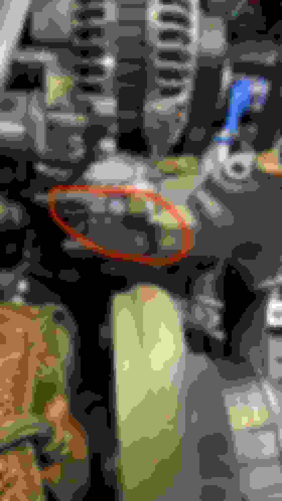
It's hard to see from the FSM diagrams, but I *think* the location circled in red is where the water thermoswitch/sensor is supposed to connect. What's there now is a sensor that was part of a Water Temp gauge. I removed the gauge but I left the sensor in because I don't have a plug handy (and also didn't wanna drain coolant to plug it). Assuming I'm right and that's where the water thermosensor goes, is it needed for the PFC to work? I assumed when the PFC sees 86 degrees (which I can see on my Commander), it should just kick the fans on if the AC is off using the same trigger that fire when I press the AC button?
the fans should turn on when it reaches the set temperature in the PFC. The water thermosensor will bump it up to another speed. Something is not wired according to the factory configuration.
the fans should turn on when it reaches the set temperature in the PFC. The water thermosensor will bump it up to another speed. Something is not wired according to the factory configuration.
Ugh. I've looked over the wiring diagram for hours and double checked my connections. I also tried some trial and error because the fans are JDM the colors were different. Each motor has 4 wires (black, yellow, green, blue) which don't line up at all with the FSM. I *think* the Black and Yellow are wires that connect to ground and the Blue and Green are the ones that connect to Power.
The cut wires are as follows: (2) Black, (2) Yellow/White, (1) Red/Yellow, (2) Blue/Orange, (1) White. This aligns with the FSM. Based on the FSM, I built two connectors, one for each Fan and grouped the wires as so:
Fan 1: Yellow/White, Red/Yellow, Black, Blue/Orange
Fan 2: Yellow/White, White, Black, Blue/Orange
I mapped the wire colors as such (RelayWireColor --> Fan Wire Color)
Fan 1: Yellow/White --> Blue, Red/Yellow --> Green, Black --> Black, Blue/Orange --> Yellow
Fan 2: Yellow/White --> Green, White --> Blue, Black --> Black, Blue/Orange --> Yellow
In this setup, when I do the test procedures here (http://www.fd3s.net/fan_test.html), the fans operate as they should. It's just the PFC not kicking them on. My brain hurts from staring at this wiring diagram but if anyone sees something I've done wrong, please let me know. What I can't find by searching this forum is what the PFC triggers to to turn on the fans. Pin 3D is the Cooling Fan Relay and I know this works because if I ground the TFA port in the diagnostic connector the fans come on. Pin 3E is Water Thermosensor and I'm wondering if this is what the PFC uses to trigger the Relay 3 that ultimately turns on the Fan based on Water temp? I'm hoping the PFC gurus know...
My fans don't have the same color wires as the harness. I did some searching and it looks like its because my fans are off a JDM car.
@arghx - I found one of your old posts and it looks like 3D is the pin that is supposed to trigger the fans so I gotta figured out what's going on there. I checked continuity at Pin 3D and relay 2 and it's good...
Update: I'm 99% sure my new wiring is right. I just went out and grounded all the points on the relay that trigger the fans:
Relay 1: Violet wire (Thermoswitch / AC Button) = Fans turn on low
Relay 2: Green/Black (ECU Selection) = Fans turn on low
Relay 3: Blue/Green (ELD Unit) = Fans turn on medium
Relay 4: Green/Black (Diagnostic Connector) = Fans turn on low
If I have AC on and I ground another relay, the fans jump up a level. As far as I can tell my wiring is good. I double checked continuity from Green/Black back to Pin 3D and there is continuity. Could my issue be in the PFC? I assume if the PFC was working, when it triggers the cooling fans via pin 3D, it is just pulling it to ground? When I unplug the connector from the relay 2 or 4 and check the Green/Black wire, its showing 11-12V. If I read the wiring diagram right (big IF), I don't think I should see any voltage on Green/Black for Relay 2 or 4 without the relay connected because the 12V should be flowing from Black/Yellow when the relay is plugged in.
Yeah the ECU should be grounding that relay to get it to kick on. I guess next step would be to see if you can let the car warm up to the point where the ECU would kick the fans on and see if that pin on the ECU has continuity to ground. If you have a Datalogit you can set the fan turn-on to a low point (like 30 deg. C) and see if it kicks on without having to wait for the car to warm up.
You've made good headway getting this going!
Is the ECU's relay the "weird" JDM relay on the fan relay bracket? I don't know if there's anything else odd ball about that relay, it's not well documented.
@DaleClark I think my ECU is the issue. If I backpin 3D and turn the ignition to ON, I get 11-12V. When the car is running I get 13+V. I set the PFC to 30 degrees using the datalogit and the fans do not come on and I still measure 11-13V at 3D. If I backpin 3d and connect it to ground, the fans turn on. If I add AC, the fans bump up a speed. This tells me the fans are wired correctly as far as my new wiring job goes. For whatever reason the ECU isn't pulling 3D to ground. I also tried with car running to 86 degrees and the PFC set at 86 degrees as well. Could my PFC be bad (for this specific function)? Otherwise the PFC works great. What am I missing here?
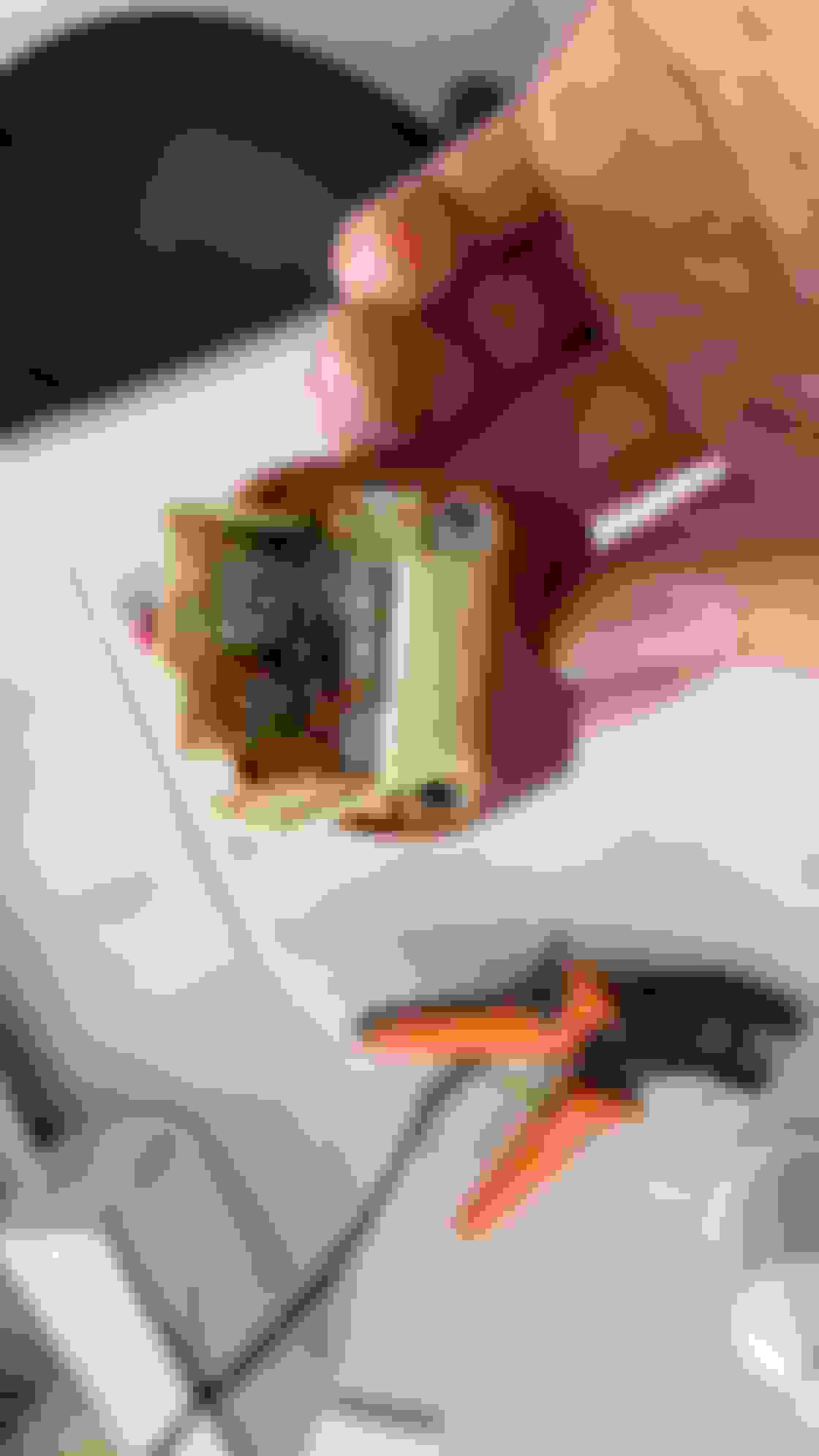
As for the relay, Relay 1 is different than relay 2-4 but this is normal, at least across 1993 years. Ray Crowe quoted me $135 for a new Relay 1. Thankfully, I found an old post here that said that Autozone Duralast Relay number 20067 is works as substitute ($18). My Relay 1 looked pretty bad and failed when I tested so I replaced it (see pic). I tested relay 2-4 and they work. Since backpinning 3D showed nothing going to ground, I assume my relays aren't the issue?
as a work around fix, why don't you just rewire the output of the ECM to the thermoswitch? If it's the FC thermoswitch it will come on at 97C, which is fine.
As for the PFC itself, what is the history of it? How old is it, did you buy it used, have you ever had any harness or electrical shorts or something? Are the factory ground wires and locations ok?
That might be my last resort. My car isn't stock but I checked all the grounds today, pulled them, wire brushed them, and then re-attached with dielectric grease. Let my car run to 107c and the thermoswitch kicked on so I have an OEM FD thermoswitch, not an FC. As for the PFC, it was on the car when I got it so I know zero about it. My wire harness definitely has been modified and I did my best to fix it as close to stock as needed for a single turbo setup.
I did notice that with the ELD indicator light on in my Command, the fans don't kick up a level. With AC on and Headlights, the fan level doesn't change. According to @DaleClark All About Fan Control post, it's also an input so I'm wondering if something also isn't right about the ELD or if this is still a PFC issue and if the two issues are related or not. I guess I need to check my ELD connections too?
@arghx I was just thinking about this, if my fans come on based on the thermoswitch, the only reason to wire it to relay 2/4 would be so that when the fans come on, they would be at a medium speed instead of a low speed? If I were to put an FC thermoswtich in, then the switch would already activate the fan at 97 without having to actually wire pin 3D. All the bypass does it provide 2 inputs and therefore give me the medium speed instead of low right?
Your wiring is modified and your cooling fan system is not really behaving as expected, so I don't want to make a prediction. What I will say is that in your situation I don't see a downside to switching to a 97C thermoswitch (not even messing with the ECU output) as it would at the very least kick your fans on earlier.