When you click on links to various merchants on this site and make a purchase, this can result in this site earning a commission. Affiliate programs and affiliations include, but are not limited to, the eBay Partner Network.
I spontaneously purchased FD. The previous owner provided me with as much information as they had but more has been discovered upon its arrival. My goal is to identify all that I can and put together a list of modifications. Any help would be greatly appreciated.
Below is a combination of information I received from the previous owner and my own inspection.
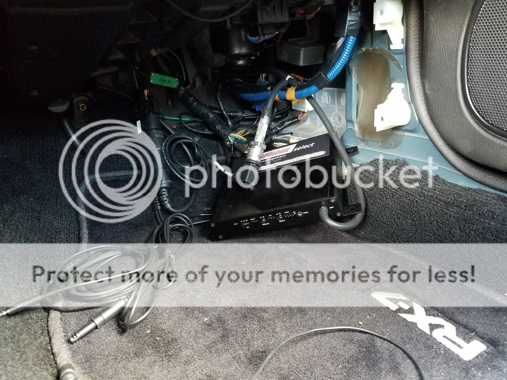
Adaptronic Series 6 RX7 FD3S ECU with a bunch of wires around it?
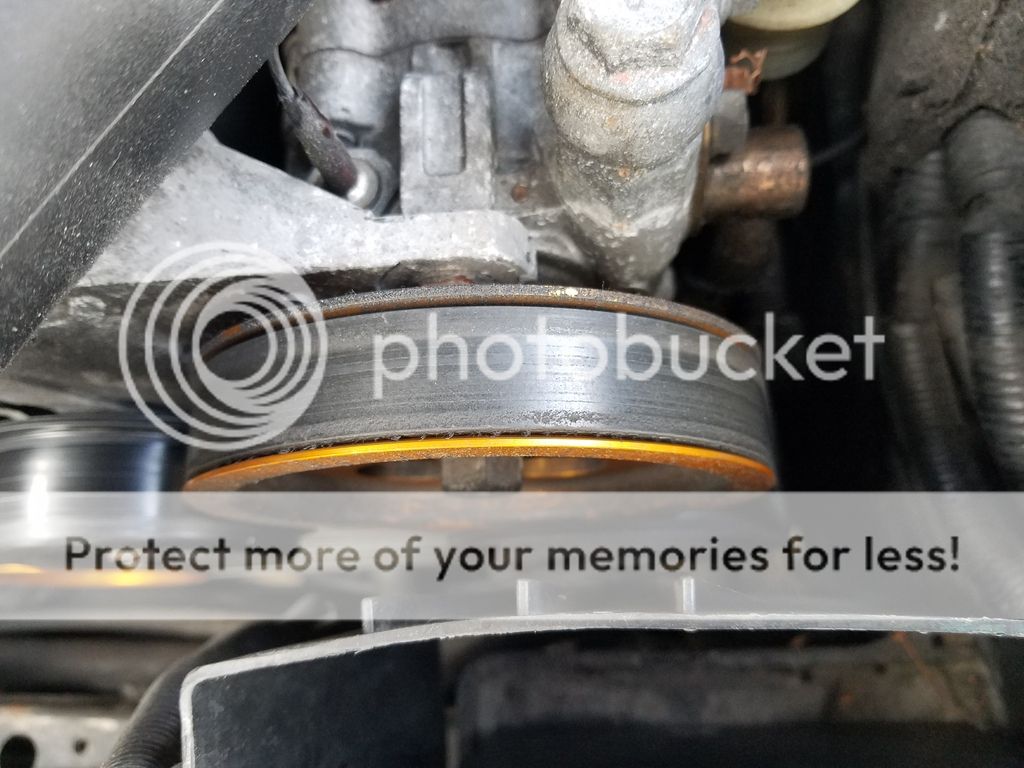
Greddy Pulley system
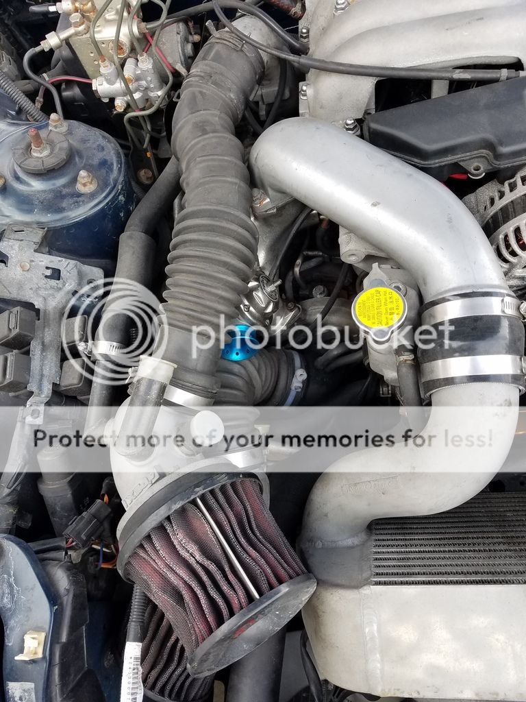
Petit racing air duct and intercooler?
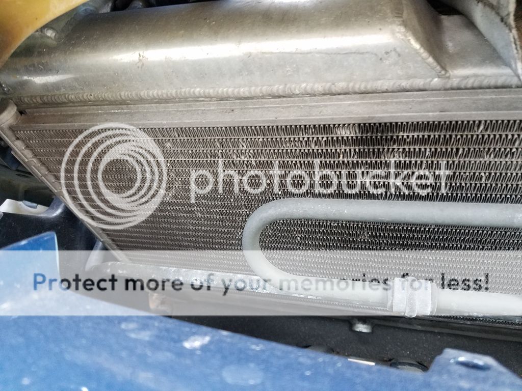
Some aftermarket radiator
Compustar alarm system with keyless entry that goes crazy unless the key manually unlocks the door. Placing key in the ignition does nothing. Ideas on how to resolve this would be great.
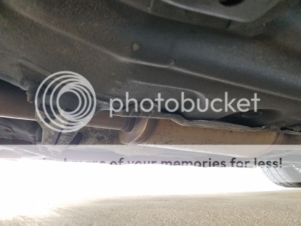
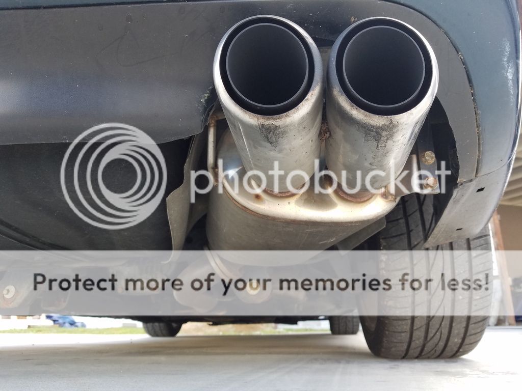
3" exhaust system with possible resonator and racing beat dual tip muffler
Greddy blow off valve
apexi intake system
unknown aftermarket wheels
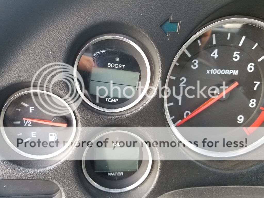
unknown temp/boost gauge
unknown water/oil gauge
99 spec front bumper
99 spec wing
possible street port
possible wideband and boost controller connected to adaptronic ecu
possible double din 3.5mm jack and usb input or charger?
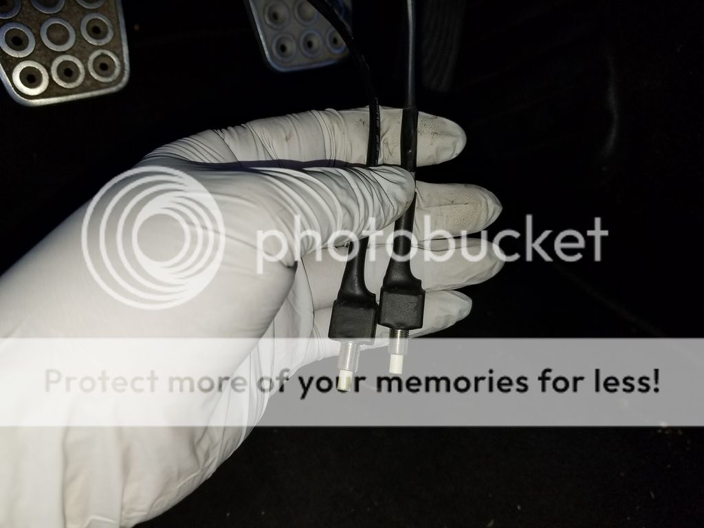
pair of buttons located under the drivers side dash?
Here are pictures if people can help identify/confirm what is what. If you need me to take more detailed pictures please don't hesitate to ask. Thanks.
racing beat dual tip exhaust
apexi intake
pettit smic ( 1gen) ?
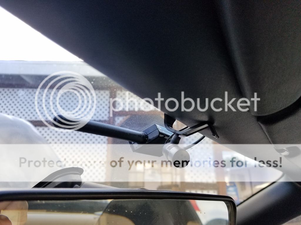
the little thing on the dash is for your nav/radio receiver? I have one hidden in my trunk tower for a double din nav system
As for the alarm, I'd probably remove it. Most of those aftermarket alarms are more of a problem than anything else.
The pullies are not Greddy, but they are aftermarket, probably one of the Tougue (sp?) pullies.
The exhaust in the middle looks to be a resonated mid pipe - that "box" seems to say Magnaflow and I think it's a muffler. Doesn't look like a high flow cat.
Definitely Racing Beat dual tip cat-back.
I think those gauges in the instrument cluster are from SPA, that was a popular mod many years ago.
So far seems like:
full 3 inch exhaust with magnaflow resonator and dual tip racing beat exhaust
apexi intake with beat up filter
1st gen pettit smic
double din radio with square nav receiver on dash?
tougue gold aluminum pulley set
SPA technique dual gauges boost/temp (DG206) and oil/water (DG203)
I'm guessing the mic is probably for the double din radio which is a alpine ina-w900
That receiver next to the mic could possible be related to the compustar alarm system? Hey Dale, I hope to keep the keyless entry and wish to install a keyless trunk release in the future. I've read people having a bunch of problems with the stock security system when paired with aftermarket systems but I'd rather rewire and find a fix if possible.
If you guys need more detailed pics, please let me know. Thanks again for all your help.
It may be easier to remove and then re-install that alarm system. So many times they're installed poorly.
Dale
I may do just that. Ill do more search on proper install of aftermarket alarm systems and identify exactly what model compustar was installed and proceed from there.
anyone have any ideas on what those buttons are that I'm holding with gloved hands?
Dale you are correct, I confirmed this by tapping the buttons when the car was on and noticed the display fluctuating accordingly. I'm going to pull up the instructions on the SPA gauges to see how to program it to my specs and make sure its working properly. On a site note I made a few more discoveries that I might need confirmation on. I'll take more pictures but it seems like the car may be setup as non-sequential and appear to have the emissions ie bac/isc block removed and blocked off.
Pair of mac Electronic boost solenoids Wasnt sure if the thermowax/fast idle was supposed to blocked off so i fabricated a plate and blocked it off anyway. If anyone can chime in and verify if its suppose to be open to air or blocked i would really appreciate it. Full function fuel system or so it says paired with a fuel lab fpr with gauge which was noted earlier.
You've got the ISC and double throttle blocked off on the back of the upper intake manifold. On the back side of the lower that's the port for the air pump air to return from that's blocked off.
Also, it looks like you may have a JDM lower intake manifold, it only has 3 vacuum ports going through the manifold and it doesn't have a place or provision for an EGR valve.
The fast idle cam assembly doesn't need a block off plate when it's removed, it's a dead circuit when that is off and it doesn't go into an air passage or anything. The cam that rides on it sometimes needs to be dealt with since if it's left on it can stick or bind the throttle body up.
Dale
Thanks Dale, great help as always. Since I fabricated that block off plate I just installed it anyhow. I'll be sure to lube up and make sure the fast idle doesn't bind open.
I was inspecting the vacuum lines there was a few areas that were vented. I'm not sure if I connect them corrected and hoped you can help with that. First I noticed the oil cap has a nipple that goes to the UIM and normally a pcv valve is in place in the hose diagrams for non-sequential setups. In my case there is no PCV valve. Is this okay or should I replace asap? There were two vacuum lines that were open. I capped one and used the other one to connect to one of the green check valves that was vented. I couldn't find any hoses laying around. Even with the diagram I struggle to identify what is what.
I was told the car had a street port. Water temp around 80 and idling fine I took a video of the exhaust so you could hear and help me determine if it does have a street port. I compared it to other videos only and the idle/exhaust note sounds similar.
Check valve I found with no end ran silicone cone hose here and connected it to the check valve I found. Also right next to the silicone there was another open vacuum line so I capped it off. Again both these vacuum lines I have no idea what they are I'm just assuming they connect to the manifold and oblivious if it goes to a sensor/solenoid of some sort. If you can help me identify what these vacuum lines are if if connecting the check valve I found to it is fine that would be great picture of the check valve I connected to one of the open vacuum lines I found saw these blocked off one goes to oil cap filler vent nipple which is lack a pvc valve can anyone very these are factory twins or jdms?Thanks again,
-groovin
For the vacuum lines, you'lll need to download the vacuum diagram and go to work. Protip: get a good copy of the vacuum diagram and put it on a thumb drive. Take it to Kinko's and have them print it on 11x17 and laminate it. Should only be $6 or so and is SO handy for working on vacuum lines.
Originally the FD had a vacuum line that went from the oil fill neck to the upper intake manifold with a PCV valve in line. In 95 Mazda removed the PCV valve and capped the intake manifold and oil neck. The oil neck has another nipple that points straight down, that goes to a metal line that runs to the primary turbo inlet duct.
Many guys remove the PCV valve. You can also go with a vented catch can. There's a LOT of stuff on that, read up and do some searching.
The turbos at first glance look like standard turbos - the 99 turbos have bolts that hold the compressor housing on and has bumps on the back side, it doesn't look like that.
If you have all the vacuum lines and solenoids the car is either sequential or the dude did a super sloppy non-sequential job.
Dale
I've been trying to follow the diagram and compare it to the car but the car seems to follow its own system. The car gets no boost until 4300 RPM. After 4300 it pulls really hard. Coupled with what was blocked off, I'm guessing its a non-sequential setup.
I'll probably just cap off the oil neck then. I'll have to figure out where that check valve comes from and connect it to the appropriate location.
You've got the ISC and double throttle blocked off on the back of the upper intake manifold. On the back side of the lower that's the port for the air pump air to return from that's blocked off.
Also, it looks like you may have a JDM lower intake manifold, it only has 3 vacuum ports going through the manifold and it doesn't have a place or provision for an EGR valve.
The fast idle cam assembly doesn't need a block off plate when it's removed, it's a dead circuit when that is off and it doesn't go into an air passage or anything. The cam that rides on it sometimes needs to be dealt with since if it's left on it can stick or bind the throttle body up.
Dale
Dale, I just recently put 2 and 2 together and discovered I was making my life more difficult than it need be. You noted a JDM lower intake manifold earlier and the vacuum diagram I kept referencing was the USDM version. I kept wondering why the diagram doesn't match the vehicle and thought this car was really foobar'd. Though they are similar tracing was more complicated because of all the added emissions crap. Finally decided to pull up a JDM schematic and my life just became simpler. SMH... could have saved me time had I realized 2+2=4 earlier.
Also did a TPS check and numbers seem more or less within spec.
(1) 2nd from top (green wire with red stripe), this goes to the 3F ECU connector. Closed throttle +V range is 0.75 to 1.25. Fully opened throttle +V range is 4.8 to 5.0.
(2) Bottom (black wire with green stripe), this goes to the 3G ECU connector. Closed throttle +V range is 0.1 to 0.7. Fully opened throttle +V range is 4.2 to 4.6.
Anyone got an idea on that connector I posted earlier?