
Maximizing Stock Ignition Output

Thread Starter
Senior Member
iTrader: (6)
Joined: Jan 2008
Posts: 436
Likes: 1
From: Montreal , Canada
Maximizing Stock Ignition Output
Many of us have gone through the trouble of rewiring the fuel pump to ensure full battery voltage and see it as a necessary "mod" to the FD to ensure proper fuel flow.
But i have not seen anyone talk about rewiring the stock ignition system ... from the factory wiring diagrams... the same sh*t wires that do not offer full battery voltage , that we have deemed inadequate to power our fuel pumps ... power our ignition coils ... i believe that energizing the coils with at least 1 extra volt is worth a rewire .. 1v+ ..is a big difference when considering the scaling factor withing the coil
also a lot of people change out the coil harness for an updated model .. but ... don't do anything about the other half of the wiring ... from the clip to the igniter ... y?
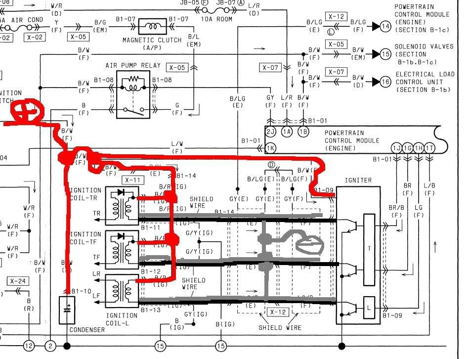
here is what i am saying ...
RED = Direct Battery .. switched .. relay switched .. whatever .. just straight from the battery ,no interior harness
Black + grey ... shielded wire from coil clips ( blue white black ) .. to igniter ..
preferably unpin both .. and install new wire .. no crpimps on cut wires
and ground the shield at the same point
what gauge ... + fuse should there be on the + .. and gauge of the signal wires ( black )
thx
But i have not seen anyone talk about rewiring the stock ignition system ... from the factory wiring diagrams... the same sh*t wires that do not offer full battery voltage , that we have deemed inadequate to power our fuel pumps ... power our ignition coils ... i believe that energizing the coils with at least 1 extra volt is worth a rewire .. 1v+ ..is a big difference when considering the scaling factor withing the coil
also a lot of people change out the coil harness for an updated model .. but ... don't do anything about the other half of the wiring ... from the clip to the igniter ... y?
here is what i am saying ...
RED = Direct Battery .. switched .. relay switched .. whatever .. just straight from the battery ,no interior harness
Black + grey ... shielded wire from coil clips ( blue white black ) .. to igniter ..
preferably unpin both .. and install new wire .. no crpimps on cut wires
and ground the shield at the same point
what gauge ... + fuse should there be on the + .. and gauge of the signal wires ( black )
thx


I did this a while back, but instead of wiring straight from the battery, I just shortened the stock wires to take a short cut. From the igniter, the 3 signal wires and 12V wire take a detour, and I was able to eliminate some wire and a few connectors (my coils were relocated though).
I soldered the outputs from the igniter to a 3-wire shielded bundle (green wire) straight to the coils.
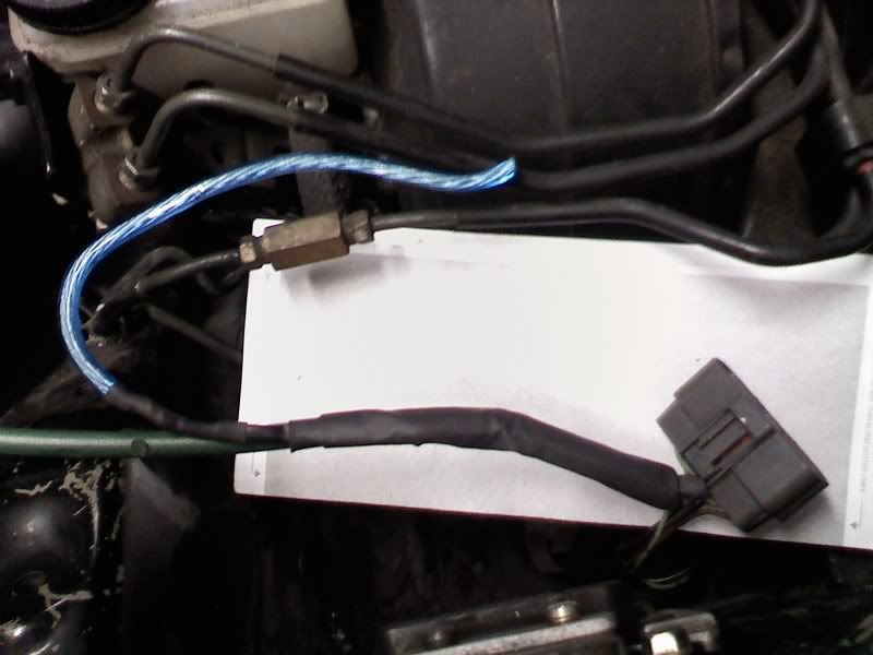
Over the solder joints I used a shielding sleeve that has a ground strap (blue wire).
I soldered the outputs from the igniter to a 3-wire shielded bundle (green wire) straight to the coils.
Over the solder joints I used a shielding sleeve that has a ground strap (blue wire).
Thread Starter
Senior Member
iTrader: (6)
Joined: Jan 2008
Posts: 436
Likes: 1
From: Montreal , Canada
also i know that the stock shield wire .. runs UP on the diagram .. ( B/LG) ...then continues into ... B-1c..Engine control system then connects near the MAP sensor... is this path necessary ...i don't understand what it does.....is this some kind of + shield wire ?...
Thread Starter
Senior Member
iTrader: (6)
Joined: Jan 2008
Posts: 436
Likes: 1
From: Montreal , Canada
I did this a while back, but instead of wiring straight from the battery, I just shortened the stock wires to take a short cut. From the igniter, the 3 signal wires and 12V wire take a detour, and I was able to eliminate some wire and a few connectors (my coils were relocated though).
I soldered the outputs from the igniter to a 3-wire shielded bundle (green wire) straight to the coils.
Over the solder joints I used a shielding sleeve that has a ground strap (blue wire).
I soldered the outputs from the igniter to a 3-wire shielded bundle (green wire) straight to the coils.
Over the solder joints I used a shielding sleeve that has a ground strap (blue wire).
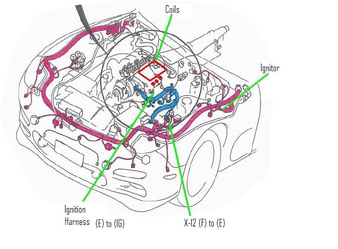
"The Front harness starts at the ECU and wraps around the entire car, inputs the ignitor, then the "shielded" output travels back down the driver's side and connects to the Emissions harness (X-12), travels toward the block where another connector breaks out the IGnition harness."
If your coils are relocated to where the cruise control was, then your wiring is doing some unnecessary back tracking and going through 2 connectors when the igniter is less than 6 inches away.
With the coils in the stock location, it makes most sense to me to re-wire the igniter to either the firewall or the passenger side straight from the ECU, then straight to the coils.
The reason that I bundled them up together inside the shielded wire is because that is how they are shielded from the factory.
Trending Topics
I'm not sure off the top of my head. Take a look at the stock wires, I think it my be 16awg? Also now that I look at it, the coil harness has each wire shielded, but if I remember correctly, they were bundled together from the igniter.
Thread Starter
Senior Member
iTrader: (6)
Joined: Jan 2008
Posts: 436
Likes: 1
From: Montreal , Canada
ok it`s done .. i will try to post pics .. my camera ...got broken ..
..
i will ask a friend with a camera to pass by this weekend possibly
the concept is ez .. just takes time
unplug coil connectors
unplug coil harness
unbolt / unplug igniter
unplug condenser( little thing attached to igniter )
now... unpin the wires from the coil connectors all 6 ( remember + is on top next to clip )
on the igniter plug, unpin the following : ( AS u look at the connector from the top the clip will be on top towards the engine ) ...
2nd from the right ( lime with black line wire )
4th from the right ( lime with white line wire )
2nd from the left ( lime with red line wire )
these are your signal wires ( note the 3 color of the lines , they are used as such on the diagram )
and
5th from the right ( Black wire with white line ) this is POWER ( + )
now.. cut the wires after the metal connector on all wires
now what you want to do is this ..
u need .. appropriate gauge wire .. ~2-3 feet of red ,white , black ... ~ 4-5 feet of red/yellow for power ... a fuse .. a standard relay .. and some male/female connectors
on one of each connectors ( 1 from coil and 1 from igniter ) attach a different color wire red white and black ... these need to be shielded .. either buy shielded wire or .. make one ..
the coil plug metal connectors are 2 kinds .. one small and one larger .. the terminal is the same but the end where the wire comes in is different , use the larger one for power and the small for igniter signal
now connect a red / black/ white wire each to a coil connector and a igniter connector . ( gauge ~ 16 i think )
after that .. run a power wire of larger gauge .. ~12 to the 3 remaining coil connectors ... u have to find an efficient way to connect these 3 power wires together
from this connection .. run a wire to the igniter remaining connector ***
now for the relay ( i bolted it up by the igniter shock tower there is a vacant .. threaded holes a bit above the ground wire that is in that area
the connector u unclipped the condenser from.. make a wire go from there , in that connector , to the relay COIL ( nothing to do with ignition coils ) power .. and then ground that nearby
bring a battery power wire direct from the battery .. to the relay LOAD .. and connect it , u can fuse this wire with a 20 amp
now what u need to do is .. from the relay .. u want connect a wire to the *** power wire running from the coils to the igniter .. and also connect the condenser ( not metal clip ) .. but the feed wire to this same junction ... .. now here is the diagram :
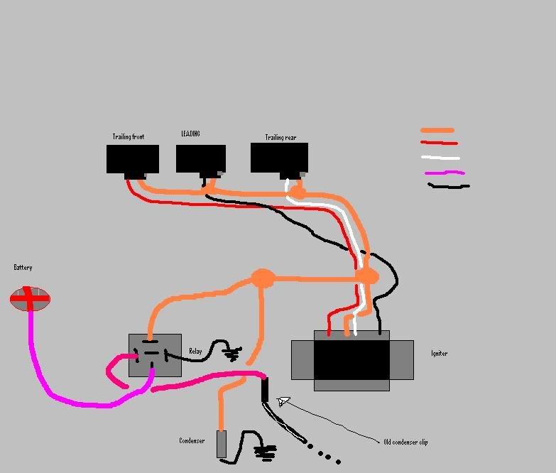
also here is a standard relay diagram used in this :
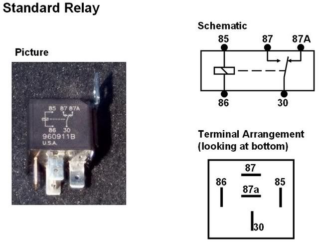
sorry in advance for any mistakes in the text .. the diagram is very accurate .. also the relative position of the wires as the connect to the relay is good
have fun
..i will ask a friend with a camera to pass by this weekend possibly
the concept is ez .. just takes time
unplug coil connectors
unplug coil harness
unbolt / unplug igniter
unplug condenser( little thing attached to igniter )
now... unpin the wires from the coil connectors all 6 ( remember + is on top next to clip )
on the igniter plug, unpin the following : ( AS u look at the connector from the top the clip will be on top towards the engine ) ...
2nd from the right ( lime with black line wire )
4th from the right ( lime with white line wire )
2nd from the left ( lime with red line wire )
these are your signal wires ( note the 3 color of the lines , they are used as such on the diagram )
and
5th from the right ( Black wire with white line ) this is POWER ( + )
now.. cut the wires after the metal connector on all wires
now what you want to do is this ..
u need .. appropriate gauge wire .. ~2-3 feet of red ,white , black ... ~ 4-5 feet of red/yellow for power ... a fuse .. a standard relay .. and some male/female connectors
on one of each connectors ( 1 from coil and 1 from igniter ) attach a different color wire red white and black ... these need to be shielded .. either buy shielded wire or .. make one ..
the coil plug metal connectors are 2 kinds .. one small and one larger .. the terminal is the same but the end where the wire comes in is different , use the larger one for power and the small for igniter signal
now connect a red / black/ white wire each to a coil connector and a igniter connector . ( gauge ~ 16 i think )
after that .. run a power wire of larger gauge .. ~12 to the 3 remaining coil connectors ... u have to find an efficient way to connect these 3 power wires together
from this connection .. run a wire to the igniter remaining connector ***
now for the relay ( i bolted it up by the igniter shock tower there is a vacant .. threaded holes a bit above the ground wire that is in that area
the connector u unclipped the condenser from.. make a wire go from there , in that connector , to the relay COIL ( nothing to do with ignition coils ) power .. and then ground that nearby
bring a battery power wire direct from the battery .. to the relay LOAD .. and connect it , u can fuse this wire with a 20 amp
now what u need to do is .. from the relay .. u want connect a wire to the *** power wire running from the coils to the igniter .. and also connect the condenser ( not metal clip ) .. but the feed wire to this same junction ... .. now here is the diagram :
also here is a standard relay diagram used in this :
sorry in advance for any mistakes in the text .. the diagram is very accurate .. also the relative position of the wires as the connect to the relay is good
have fun
Ok im bumping a old thread, yeah i know. Im just very interested in knowing who has done this mod and what your results have been? Im always looking to improve on things ie fuel pump rewire so of course this topic has my attention. thanks
No the T2 coil is just a more beefy coil that people like to use when they upgrade the ignition with an amp. This is a rewire of the coils nothing to do with swapping them.
Thread Starter
Senior Member
iTrader: (6)
Joined: Jan 2008
Posts: 436
Likes: 1
From: Montreal , Canada
so far i have ~2000 km`s or so with this upgrade and no problems ... it`s really simple .. just LONG ... but it does take some organization skills .. did i mention .. LONG ..

Thread
Thread Starter
Forum
Replies
Last Post
Skeese
Adaptronic Engine Mgmt - AUS
65
Mar 28, 2017 03:30 PM
freq
2nd Generation Specific (1986-1992)
0
Aug 21, 2015 03:30 PM