When you click on links to various merchants on this site and make a purchase, this can result in this site earning a commission. Affiliate programs and affiliations include, but are not limited to, the eBay Partner Network.
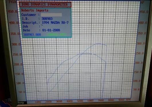
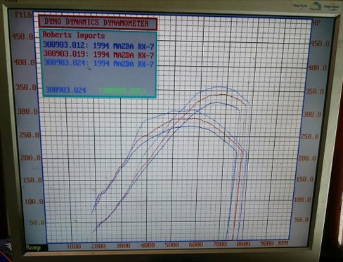
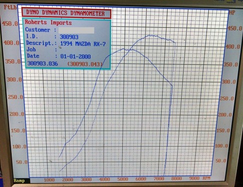
Recently finished up the install of the new Syvecs S6 Plus on a customer's FD and wanted to share the results. This car has stock ports, relatively short runner exhaust manifold, stock FD upper, Excessive LIM. Turbo has the EWG 1.05 exhaust housing. It's been interesting to have the actual, well documented, real world results and go back and read the speculation from the last couple years since this turbo was introduced. At any rate, below are HP and torque graphs for 10 psi, 12/14/16 psi, and 20 psi, in that order. The first two charts were run on 93 octane gasoline. The 20 psi chart was run with E80. We intended to run it at 24 psi on ethanol but experienced ignition breakup on two attempted pulls and we ran out of time for any kind of diagnosis. We'll hopefully revisit that issue soon. All runs were done in standard Dyno Dynamics load mode, not their shootout mode. Ambient temp in the shop was 101. Inlet temp just before the turbo hovered around 120. Intake manifold temps at 16 psi were 140 peak and 20 psi were 160 peak, for reference. We could certainly do better on the charge cooling! In the end, I felt the power on gasoline was right about where it should be but was very impressed with the power on ethanol. I ran the car at 16 psi on ethanol but didn't get a screenshot of the results. Peak power was right around +30 over the same results with gasoline. Pretty typical but always an eye opener.
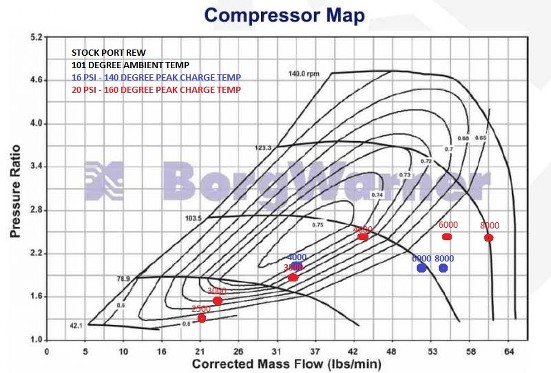
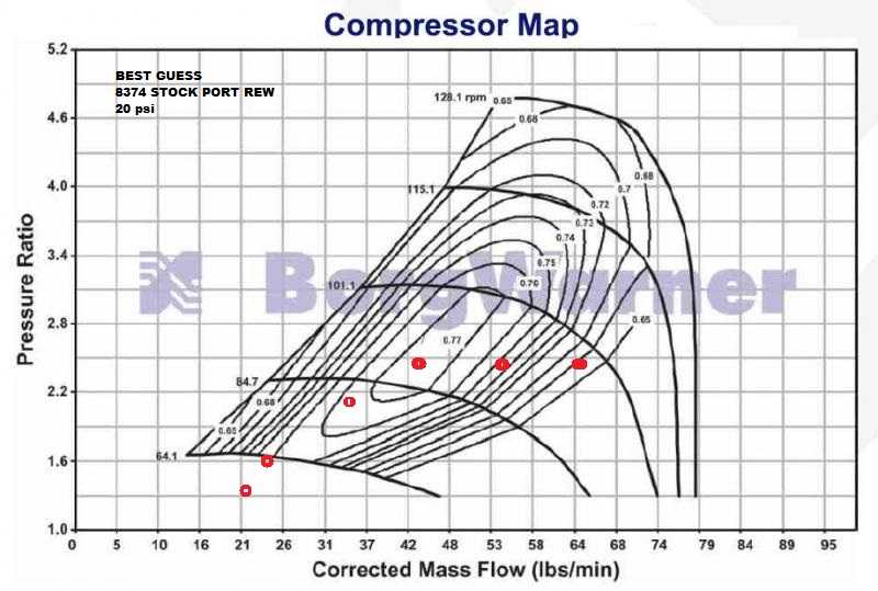
Below is the compressor map for the 7670 with plots for 16 psi (blue) and 20 psi (red) taken from our datalogs of MAP and turbo speed. As you can see, it just confirms what everyone suspected. The compressor is well on the small side for the rotary engine. At 8000 rpm at 20 psi we're well past anything close to efficient. On this engine, 8000 is well passed peak power anyway but even at 6000 rpm at 20 psi we're abusing the little compressor. I'm interested to see what the results of lowering the intake temps to a more reasonable level would be. That would allow the compressor to run more efficiently and move the data points to the left slightly. Going forward, once we get the ignition to cooperate and allow us to run more boost, we'll use the ECU to limit max turbo shaft speed and turn the boost up in the mid-range. So we'll end up with more boost in the lower revs with pressure tapering off at higher revs. The ECU has a turbo speed function that allows you to control the wastegate v. shaft speed. This was designed more for limited turbo size specs in various racing series and is very popular in rally. It just so happens we're also trying to maximize an undersized compressor and is just what we need. Of course, Geoff Raicer of Full-Race predicted this exact scenario a few years ago when this compressor was first being discussed. Listen to the experts!
Last edited by C. Ludwig; Aug 21, 2015 at 10:57 AM.
Nice! This is the first time I've seen good data on the 1.05 A/R turbine housing. For comparison, I have a 7670 with a 0.92 IWG housing, and I'm seeing 12psi by ~2800 rpm. It looks like this setup hits 12psi at ~3300-3400? (I'm looking at the second dyno where the 14psi torque curve breaks away from the 12psi curve, aka where the wastegate opens for 12psi). I also had a cold air intake giving me ambient compressor inlet temps, which surely helps get some more mass flow through the engine at low rpm to spool the turbo sooner.
What's the current ignition setup? and what is the planned fix?
Same question for charge cooling, FMIC? VMIC? or just poor tuning conditions (no fans?)?
Pre turbo AI?
I have ridden in this car before with a powerfc. The car back then pulled very well down low, back then it had a street port and water injection. The car was very quick.
The precision turbo's arent even close in response, nothing is that i have ridden in. The GT35R turbos arent as close either as I am talking about down low pull. as you can see the 20PSI pull netted 200 FT-lbs at 3K rpms. Thats 1K rpms sooner than GT35R netting 200ft-lbs at 4K.
Nice! This is the first time I've seen good data on the 1.05 A/R turbine housing. For comparison, I have a 7670 with a 0.92 IWG housing, and I'm seeing 12psi by ~2800 rpm. It looks like this setup hits 12psi at ~3300-3400? (I'm looking at the second dyno where the 14psi torque curve breaks away from the 12psi curve, aka where the wastegate opens for 12psi). I also had a cold air intake giving me ambient compressor inlet temps, which surely helps get some more mass flow through the engine at low rpm to spool the turbo sooner.
You nailed it. 12 psi in the 3300 range. Of course, on the dyno that is effected by a few different factors. For the dyno pulls I would load it at about 1800 rpm, mat the throttle and allow it to stabilize for a few seconds, then release the dyno to make the sweep. The limited driving I've done with the car on the street says the dyno behavior is very close to what it does on the street.
Originally Posted by silentblu
What's the current ignition setup? and what is the planned fix?
Same question for charge cooling, FMIC? VMIC? or just poor tuning conditions (no fans?)?
Pre turbo AI?
IGN-1A coils. Owner has them mounted on top of the engine under the intake. It's a great solution from a packaging stand point but I'm guessing the heat, especially the stagnant air of the dyno environment isn't doing them any favors. I wanted to tighten up the plug gap but we have a 6pm curfew on the dyno and we were out of time. The coils, plugs, and wires are up to the task, I'm just not sure the packaging solution is best.
Owner has a nice IC but didn't have a chance to finish the ducting before we received the car. It's a v-mount deal and the IC is just kind of currently hanging out in space with lots of area for air to move around it instead of through it. In addition, I wasn't very proactive in trying to move our fans around to help the issue. We concentrated on keeping the coolant and oil in check and not so much the charge temp. I have no doubt, given the attention to detail the owner has given to the rest of the car, that he'll address the ducting and solve the issue.
Originally Posted by fendamonky
Looking good man! What were your impressions on mapping the S6+, in comparison to other ECUs you've worked with??
Syvecs isn't going to be for everyone. The learning curve is pretty steep. There are just a LOT of parameters that need to be setup and in this day of everyone expecting plug and play and autotune, few are going to have the patience to learn the system and be able to make it work to its capability. For those that want top-shelf capability, Syvecs is on a different tier than most of the other systems RX-7 enthusiasts are familiar with. The only popular systems I'd put on par with it are Motec and Pectel. The attractive thing about Syvecs, relative to those two, is that it comes from the factory fully enabled. No additional fees for traction control, Lambda, logging, etc. Updates are free and no need to renew a yearly license to use the product you purchased. The cost is also relatively low compared to those two when you stack them up next to each other. IMO, for the few that want a system that has been proven in ALMS, WEC, LeMans, WRC, etc., Syvecs is a great balance of capability and price. Their tech support has also been wonderful. They've written OMP control code just for this car. Doing that inadvertently created an issue with the fuel pump output not working correctly and we had a firmware fix next day after making them aware of the issue. This one ECU is the only one they have doing what we're doing and we're getting support like we're selling 1000 of them. Meanwhile their also developing $15k packages for Lamborghinis. My guess we would get back burnered, but that hasn't happened.
Originally Posted by fritts
Any time on the road with the car and how was its response compared to say the precision's?
The only other rotarys I've driven with similarly sized turbos were an old T4 57-trim Garrett and Carter Thompson's autocrosser with the little Precision. This combo responds like the little 57-trim but with WAY more top end potential. You get your cake and can eat it too. I mean, this is a 57mm turbo with 500 whp potential! Who would of even considered that possible 10 years ago? Carter's car probably hit harder at 2500 rpm but, again, didn't have the top end potential. His compressor signed off a little earlier. If we get the intake temps in check, this compressor may be able to do 24 psi all the way to 7500 rpm. While the compressor isn't properly sized for the engine, it works pretty well and if you can keep from overspeeding the turbo by simply not abusing it, it should last a good long time. All that said, Elliot says the 8374 responds the same but is more properly sized so why bother with the 7670?
Originally Posted by lOOkatme
I have ridden in this car before with a powerfc. The car back then pulled very well down low, back then it had a street port and water injection. The car was very quick.
The precision turbo's arent even close in response, nothing is that i have ridden in. The GT35R turbos arent as close either as I am talking about down low pull. as you can see the 20PSI pull netted 200 FT-lbs at 3K rpms. Thats 1K rpms sooner than GT35R netting 200ft-lbs at 4K.
True. A 35R feels laggy by comparison but it is a bigger wheel. A GTX3076 would be a more apple to apple comparison.
Originally Posted by BLUE TII
Nice to see more results!
How would you compare the 7670 to the old 60-1 since they are the same size compressor?
Once you get the ignition working is the plan to turn up the boost to where this turbo is more efficient?
Not even close. The technology is obvious once you start comparing the two. Looking at the map, I'd say the 60-1 is not going to like 123,000 rpm and will sign off up top. The ones I've driven had way more lag too.
Yes, the plan is for 24 psi on E85. I just don't see the turbo supporting any more than that at higher revs. We could hit it harder in the mid-range while limiting turbo speed up top but then you end up with a less linear power band. In a max effort race engine where you're limited by rules on turbo size, that would be the way to approach it. Not sure it's the ultimate goal for the owner. That's his call.
Last edited by C. Ludwig; Aug 22, 2015 at 07:44 AM.
My best guess based on what we've seen with the 7670 of what the plot would look like at 20 psi with a 8374. The 8374 appears to be perfect for a stock port engine.
By using those points above, they fit very well on an EFR 9180 compressor map. How well would the EFR9180 .92 AR work out with those points. they seem to all fit within the compressor map of the 9180.
How would you compare the 7670 to the old 60-1 since they are the same size compressor?
Once you get the ignition working is the plan to turn up the boost to where this turbo is more efficient?
------------- Not even close. The technology is obvious once you start comparing the two. Looking at the map, I'd say the 60-1 is not going to like 123,000 rpm and will sign off up top. The ones I've driven had way more lag too.
Yes, the plan is for 24 psi on E85. I just don't see the turbo supporting any more than that at higher revs. We could hit it harder in the mid-range while limiting turbo speed up top but then you end up with a less linear power band. In a max effort race engine where you're limited by rules on turbo size, that would be the way to approach it. Not sure it's the ultimate goal for the owner. That's his call.
-------------
I was more wondering if you found the same results between 60-1s and 7670 on your dyno/experience as I did.
60-1 made way more power in the low pressure ratios (30rwhp more @10psi), but like you said the 60-1 was done making power @16-18psi where the 7670 just started making more power than the 60-1 around that boost.
On both my 60-1 and 7670 set ups on DD standard mode the dyno didn't load the car nearly enough in the low rpm to spool the turbo like on the road. I mean, you must have seen that in the steady state tuning where you were hitting full boost at 3,300rpm instead of 12psi.
Your peak power on DD looks same as mine per boost, but like you said we were running it up to high boost in the low rpms and fading to that boost in the high rpms, so we had 70ftlbs more @ 3-4,000rpm and it crashed back down to your torque line @ 5,000rpm.
I've never had a 60-1 on the dyno so nothing to compare it to. You made 330 on a DD at 10 psi with a 60-1?
There's no reason a DD shouldn't be able to create as much load as you want. In sweep mode you can load the dyno at any RPM and hold the engine, just like steady state. Flat foot it, build all the boost it will build and then release it for the sweep. Whether or not the dyno loads similarly to the street from that point is simply a matter of ramp rate. I would counter that you can simulate more load on the dyno than you could see on the street. No reason you shouldn't be able to have the same, better, or worse response on a DD as you do on the street. It's all in how you use the tool.
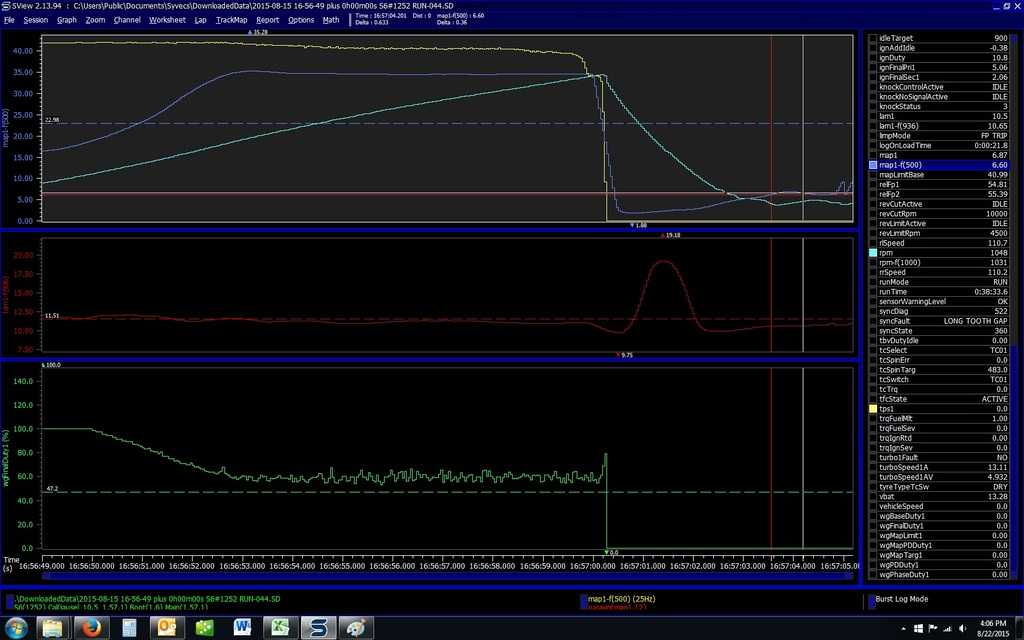
Log below of a 20 psi pull. Revs, TPS, and MAP at top, AFR in middle, and boost controller DC at bottom. Log starts at 2000 rpm, ends at 8000.
Nice results!
For those reading shoot out mode mimicks a dynojet( adds around 15percent more power). So this car is making some serious power per psi for the turbo frame.
I've never had a 60-1 on the dyno so nothing to compare it to. You made 330 on a DD at 10 psi with a 60-1?
Nope, the 60-1 was 295@ 10psi on the DD in standard and the 7670 only mustered 270.
I think I just figured it out though! Looks like the 7670 had consistent boost drop at high rpms and I was looking at peak boost.
There's no reason a DD shouldn't be able to create as much load as you want. In sweep mode you can load the dyno at any RPM and hold the engine, just like steady state. Flat foot it, build all the boost it will build and then release it for the sweep. Whether or not the dyno loads similarly to the street from that point is simply a matter of ramp rate. I would counter that you can simulate more load on the dyno than you could see on the street. No reason you shouldn't be able to have the same, better, or worse response on a DD as you do on the street. It's all in how you use the tool.
Yup, that is what we did. As a quickie fix we adjusted the DD ramp rate when doing sweeps with the 60-1 so full boost was same RPM as in actual use and used same settings for sweeps on 7670.
Later I recorded a road 4th gear 1,500rpm-7,500rpm pull with the 7670 so we could set the full range ramp rates as the DD was putting too much load on 5-7,000rpm range, but I never got around to inputting those accel figures.
Turblown Nice results!
For those reading shoot out mode mimicks a dynojet( adds around 15percent more power). So this car is making some serious power per psi for the turbo frame.
Exactly! My 369 DD was 420 Dynojet the next weekend.
That 430 DD on E885 is blowing my mind! That is 490 Dynojet.
Good thread. Nice to see you using the dyno brake for speed sweeps. It gets much more consistent data that way.
Questions about your testing:
What was your engine speed ramp rate? Rpm/sec or total time
You mention compressor shaft speed. Did you have a sensor hooked up, and if so do you have any charts to share?
How is your air mass flow for compressor map plotting being determined? Do you have an air meter or fuel flow meter (to back calculate airflow with wide and AFR) in the shop or are you estimating using a formula?
Would it be possible to hook up a pressure transducer to the compressor inlet in order to increase the accuracy of the pressure ratio plotting? I say this because using Manifold pressure is showing you to be off the compressor map, when the y axis coordinate would shift upward if you measured the pressure drop at the inlet.
Normally using manifold pressure is close enough, but here if you take the compressor outlet pressure and inlet pressure you'll get a more accurate plot.
Dyno ramp rate is set as kph/second. I normally use 120 or 12.0 kph/s. Doing a rough conversion using the actual wheel speed log from the ECU is shown to be a bit higher than that but close.
BW sensor in the turbo. The compressor map above has shaft speed v. PR v. RPM plotted on it for 16 and 20 psi. Not sure what more you'd want to see. I do have logs of shaft speed but the info is given on the compressor map.
Flow mass is determined by the compressor. Shaft speed and PR determine the coordinate plot for the 7670 map. The points on the 8374 map were transposed assuming the mass rate at a given engine RPM and PR on the 7670 would be the same on the 8374. The difference being the larger compressor would need less shaft speed to make the same mass number. That assumption takes some liberty but it's going to be closely representative of the actual results.
Good point on turbo inlet pressure. I assumed 14.7 psi. Actual ambient pressure was actually slightly higher at 30.19 in/hg iirc. No doubt there is a slightly lower pressure than 14.7 psi at the compressor inlet and the correct value would push the PR up in the map as you said. It's interesting to note, from a PR perspective, that a restrictive pre-turbo inlet would actually push the compressor into a more efficient part of the map. Surely though the restriction would create the need for more shaft speed to generate the mass number required to feed the engine and you'd make that problem even worse.
TeamRX8 You might consider overlaying the 7163 Indy and 7670 maps
7163 would be even more "too small" by C. Ludwig's measurements as he is pointing out how the high rpm full load points on the map don't run through the peak efficiency islands.
--------
I will point out however that if his dyno loaded as in actual use I believe it would show at the 20psi setting the motor does run through the peak efficiency islands @ 3-4,000rpm. In addition, the plotted points would be closer to the surge line while building boost.
Reason I say this is in 4th gear my 7670 hits-
1.5P/R (8psi) @2,500rpm
2P/R (14.7psi) @2,800rpm
2.36P/R (20psi) @3,000rpm
2.77P/R (26psi) @3,300rpm.
Do you want a turbo that runs through its peak efficiency at low rpm and high boost?
Only if you are trying to maximize low rpm torque (at the expense of peak power).
If your race "track" is too small then maybe a turbo that is too small suits it well.
If you are choosing between a 400hp positive displacement supercharger the 7670 I think you will find the turbo is still more efficient.
--------------
Yeah, I want the efficiency at high boost and low rpm and the at high boost high rpm so I am tempted by sequential 7163 for the FD.
Shaft speed and PR determine the coordinate plot for the 7670 map.
Makes sense. I see now that you explained that in your first post, sorry I didn't catch that.
Good point on turbo inlet pressure. I assumed 14.7 psi. Actual ambient pressure was actually slightly higher at 30.19 in/hg iirc. No doubt there is a slightly lower pressure than 14.7 psi at the compressor inlet and the correct value would push the PR up in the map as you said. It's interesting to note, from a PR perspective, that a restrictive pre-turbo inlet would actually push the compressor into a more efficient part of the map. Surely though the restriction would create the need for more shaft speed to generate the mass number required to feed the engine and you'd make that problem even worse.
Yeah I also wonder about pressure drop across the intercooler system. With manifold pressure for plotting the y axis, rather than a measured compressor outlet pressure it could underestimate the pressure ratio by some amount.
It's conceivable that a ~2.2 pressure ratio calculated using ratio of manifold pressure to ambient pressure could become a 2.3 or 2.55, maybe even higher, due to pressure drops in the intake system and charge piping/intercooler. With those higher pressure ratios the compressor map plotting doesn't look as ugly. The pressure ratio calculation would be more sensitive to inlet restriction (size of air filter etc) than pressure drop across the intercooler, because it's a ratio of outlet pressure / inlet pressure.
I did do some quick plotting for the 6000rpm 16psi point assuming we added 1psi and then 2psi of pressure drop equally to the intake before the turbo and the charge piping/intercooler system.
Without measurements of actual pressure drop it's only speculation though. You'd have to tap the compressor housing or air filter for inlet pressure, and maybe T off the boost controller solenoid line for outlet pressure.
Very good points! I doubt I'll have time to do that testing. Maybe we can twist the owners arm to get the data at a later time. I'm also curious about how charge temp effects the work load on the compressor. Since the compressor map is built at a much lower temp than we were running it at. The large change in air density is going to skew the results as well.
Originally Posted by arghx
Makes sense. I see now that you explained that in your first post, sorry I didn't catch that.
Yeah I also wonder about pressure drop across the intercooler system. With manifold pressure for plotting the y axis, rather than a measured compressor outlet pressure it could underestimate the pressure ratio by some amount.
It's conceivable that a ~2.2 pressure ratio calculated using ratio of manifold pressure to ambient pressure could become a 2.3 or 2.55, maybe even higher, due to pressure drops in the intake system and charge piping/intercooler. With those higher pressure ratios the compressor map plotting doesn't look as ugly. The pressure ratio calculation would be more sensitive to inlet restriction (size of air filter etc) than pressure drop across the intercooler, because it's a ratio of outlet pressure / inlet pressure.
I did do some quick plotting for the 6000rpm 16psi point assuming we added 1psi and then 2psi of pressure drop equally to the intake before the turbo and the charge piping/intercooler system.
Without measurements of actual pressure drop it's only speculation though. You'd have to tap the compressor housing or air filter for inlet pressure, and maybe T off the boost controller solenoid line for outlet pressure.
In other words, you didn't actually overlay the two maps as I suggested
at the expense of high rpm power you get 14+ psi @ 2000 rpm
Ultimately the question is; where do you want the 5500 rpm powerband range of response and power to fall .... the stall flow end of the 7670 range is only 4 - 5 lb/hr more than the 7163. I do agree that the 7163 is too small for "high rpm" E85/race fuel power, but that's not what I suggest using it for.
My point is that there are some unique features on the 7163 design that distinguish it from the other EFR turbos that rarely get touched on ... but what's faster is not always about high rpm power, like on a twisty canyon road or autox course. It seems to me like Turblown was misquoted earlier:
In the case of the 7163 vs 7670, the 7670 only really offers an advantage for high PR ... just don't skimp on some cheapo, poorly setup intercooler design that can't effectively compensate for where the turbo will operate.
It seems to me that one of must have completely misinterpreted what CL was saying about what 'seems' to be an undersize compressor vs using the shaft speed sensor for very specific reasons. I took it to mean that he's suggesting you should think outside what is the commonly accepted box here. I'm suggesting that you take one one more mothr-may-I step out ... but I also understand people hungering for high rpm power over anything else are 't ooen to the opposite end of the rpm range discussion.
It all comes down to the overall system design and end goal, which is not always some kind of street racer free for all. As you're aware, putting it all to the ground is another consideration. Obviously even a 7670 is a poor choice when there are no constraints ...
Or just go run the numbers for 16 psi from 2000 - 8500 on Matchbot ... still some room for boost vs. rpm across the mid-range
(2000, 3000, 4500, 6000, 7500, 8500)
I have no clue how a supercharger enters into the discussion, absolutely no comparison to a properly designed turbo for a rotary engine
Originally Posted by BLUE TII
TeamRX8 You might consider overlaying the 7163 Indy and 7670 maps
I
7163 would be even more "too small" by C. Ludwig's measurements as he is pointing out how the high rpm full load points on the map don't run through the peak efficiency islands.
--------
I will point out however that if his dyno loaded as in actual use I believe it would show at the 20psi setting the motor does run through the peak efficiency islands @ 3-4,000rpm. In addition, the plotted points would be closer to the surge line while building boost.
Reason I say this is in 4th gear my 7670 hits-
1.5P/R (8psi) @2,500rpm
2P/R (14.7psi) @2,800rpm
2.36P/R (20psi) @3,000rpm
2.77P/R (26psi) @3,300rpm.
Do you want a turbo that runs through its peak efficiency at low rpm and high boost?
Only if you are trying to maximize low rpm torque (at the expense of peak power).
If your race "track" is too small then maybe a turbo that is too small suits it well.
If you are choosing between a 400hp positive displacement supercharger the 7670 I think you will find the turbo is still more efficient.
--------------
Yeah, I want the efficiency at high boost and low rpm and the at high boost high rpm so I am tempted by sequential 7163 for the FD.
In other words, you didn't actually overlay the two maps as I suggested
at the expense of high rpm power you get 14+ psi @ 2000 rpm
I have compared all the EFR compressor maps and the 7163 has the most favorable surge line (even compared to some of the smaller EFRs) which is what you are talking about.
You have to have enough exhaust energy to spin the turbo up to the surge line to take advantage of that.
No one is operating the 7670 at the surge line yet on a rotary. Just barely into surge on the 8374.
-------------
I will be trying to get closer to the surge line on my 7670 by using the same 1.03 T4 divided exhaust housing on my FD as on my FC, but using the stock sequential manifold.
This way I can make a cheap durable variable area exhaust turbo (smaller runners into one turbo manifold runner/turbo scroll) to spool the 7670 to the surge line at a lower rpm and then switch to the full dual runners/scrolls at higher rpm.
--------------
Next step as you say is I would like to do the sequential 7163 where it would use the smaller T2 flange 0.85AR on the same small runner sequential switching manifold and then open another 7163 with T2 flange 0.85AR exhaust housing for the top end.
Yes, if we can get a 7163 near the surgeline at low RPMs we will have unprecedented low RPM torque for a rotary.
Last edited by BLUE TII; Aug 26, 2015 at 12:18 PM.
i really like the 7163 comp map, problem is it is mated with a factory-sized turbine wheel. I wish you could make a 7170.. bolt a 7163 compressor to a 7670 hot side and it would be perfect. by buddy at bw says not possible though
Last edited by gxl90rx7; Aug 26, 2015 at 06:37 PM.
In other words, you didn't actually overlay the two maps as I suggested
at the expense of high rpm power you get 14+ psi @ 2000 rpm
I have compared all the EFR compressor maps and the 7163 has the most favorable surge line (even compared to some of the smaller EFRs) which is what you are talking about.
You have to have enough exhaust energy to spin the turbo up to the surge line to take advantage of that.
No one is operating the 7670 at the surge line yet on a rotary. Just barely into surge on the 8374.
-------------
Because nobody is aiming for that end of the powerband with their turbine housing choices .... it's just not the conventional thing to do, especially on this forum ...
the 7163 map includes much lower efficiency parts of the map then the other turbo's. it goes down to 58% while the 7670 and 8374 compressor maps do not. tough to compare.