When you click on links to various merchants on this site and make a purchase, this can result in this site earning a commission. Affiliate programs and affiliations include, but are not limited to, the eBay Partner Network.
I really appreciate Dale, Gadd, and everyone else from the fuel pump rewire thread located in the 3rd gen FAQ. The information there allowed me to perform this modification with a few changes of my own. It is also great knowing the fuel pump speed relay is not affected by this modification. Here is my variation of the fuel pump rewire modification.
Parts required:
Wire cutter
Wire stripper
Wire Terminal Crimper or soldering iron/flux/solder
10awg wire preferably blue to match the original wire. 5" should be enough.
Spade female terminal end
Fuse box ATC fuse female terminal end
Heat shrink (marine heat shrink have glue inside that helps with water proofing and sealing)
Heat gun
Terminal removal tools or a pair of fine jewelers flat head screw drivers
10mm socket
Ratchet
Needle nose pliers
Electrical tape
20amp atc fuse
Procedure:
As Gadd noted, the fuse box holding the open circuit relay (fuel pump relay) has 3 atc spade fuses with 2 open slots on the bottom. The second to the last slot has a black 10awg power wire going to one end while the other end is open. This open slot will be the new connecting point essentially replacing the 10awg blue wire going to the open circuit relay.
First things first, disconnected the negative battery terminal and place secure it away from the positive terminal.
Locate the fuse box containing the open circuit relay (fuse box closest to the driver�s side strut tower).
Remove the open circuit relay and place aside. Using a 10mm socket and ratchet remove the 10mm nut holding the fuse box in place. Open the lid and remove the black power wire, also held in place by a 10mm nut, to increase mobility and access to the fuse box.
On the opposite side is a metal bracket with a plastic retention clip holding the fuse box.
Depress the plastic clip and pull the box up. With the box out remove the bottom cover by carefully prying away the four clips with a flat head screw driver. The underside cover should pop right off.
The wires are now exposed. The relays have a yellow retention clip that support the wires and prevent them from moving and falling out. Remove this clip using a flat head screwdriver by depressing the ends and pulling on the yellow clip. The wires coming out of it may impede its path and making removal difficult so make sure to straighten out the wires as much as possible. It is on pretty tight. Pliers may be helpful in pulling while you depress the sides and wiggle it out. Take note of how it came out because you�ll need to put in back in the same way and it is a pain in the ***.
Once out locate the blue wire, just blue, not the blue/red wire. The blue wire = power from the battery and the blue/red wire = going to the fuel pump. From the top of the fuse box, using the appropriate terminal removal tool (even a fine precision jewelers flat head screw driver will work) pull away the black retention clip from the female spade terminal and pull the blue wire out with your hands or pliers.
Cover this terminal with electrical tape followed by some heat shrink it to hold everything in place. This wire is no longer needed. Next we need to create the wire that is replacing the blue wire and connects to the open fuse slot with the 10awg black power wire. Cut 5� of 10awg blue wire. Strip one end to the appropriate size. Crimp or solder this end with a fuse box atc fuse female terminal end. Cut (2) appropriate sized pieces of heat shrink and slip them over from the other end of the wire. On this end crimp or solder a female spade terminal end. Cover both ends with the heat shrink wrap and secure in place using a heat gun.
Pull out one of the fuses from the fuse box and look at the terminals noting their orientation. Using them as a guide, place the fuse box atc fuse female terminal end of the wire you just made into the opposing side of the fuse slot where the 10awg black power wire is located. It should lock in place.
Now look at the top of the fuse box and take note of the female terminal positions for the open circuit relay. Place the other end of the wire you just created in the location the previous blue wire was removed from. This end should also lock in place.
Line up the open circuit relay wires and reinstall the yellow retention clip. There are eight legs that go in a specific way. Make sure to line them up and guide them in with the fine precision jewelers flat head screw driver as you push the clip back in place. Organize the wires and reinstall the fuse box�s bottom covers ensuring all four clips snap in place.
Place the fuse box back on its mounting location. Make sure the side connected to the metal bracket snaps in place. Reinstall the 10mm nut to secure the fuse box. Place the black power cord back and secure with the previously remove 10mm nut as well. Reinstall the open circuit relay. Install the 20amp atc fuse in the 2nd to last slot with the 10awg black power wire and your newly installed 10awg blue wire. Reconnect the negative battery terminal and start the car to confirm the pump is working.
Hope this is helpful for those who are interested. Thank you again to the RX7club community.
OK, where in the world did you find the crimp on ATC female fuse terminal? I've had zero luck finding one locally.
Going to Google around for a source.
Also, looking at it, you can just peel back the main harness going to the fuse box, cut the blue wire back there, crimp on the ATC connector, and push it into the fuse spot. Saves having to replace the fuse terminal, pulling that pin out, and re-uses the wire.
Dale
Finding it locally was impossible. I had to order it online.
pulling back the harness to get about 5" of wire and crimping the new terminal in place then placing that end in the fuse box is definitely easier, quicker, and gets the same results. That yellow retaining clip is annoying but not annoying enough for me to want to cut the original wire. If I can help it, I prefer not to hack up the oem harness.
Do you have a specific crimp part number? Or am I missing it in the original post?
From what I am gathering, this just bypasses the fuel pump resistor? Would this be sufficient for a Walbro 485?
No specific part number. As long as it does a bare wire crimp along with an insulation crimp and covers the wire size you use and the type of terminal/connector. So if your using 10awg make sure it crimps 10awg bare wire and its insulation. If your using 12awg or 14awg same thing. 12awg and 14awg are more common.
This mod does not bypass the resistor. If you review the fuel pump wiring diagram you will see that the oem power wire passes through multiple connection points then through the ignition and finally the open circuit relay. When you perform this mod you are bypassing everything mentioned previously and get power directly from the battery.
Here is a diagram borrowed from another thread. This is what is essentially being done.
Hell, it was fun to find those terminals in the US!
The fuel pressure regulator should keep fuel pressure in check. The problem comes if you are using a lot of fuel and the fuel pump can't keep up - the FPR is doing its best to maintain pressure but the fuel pump has low voltage so it's not running at the full potential.
If you can't find that fuse terminal you can do my old version of this rewire with an external in-line fuse. Those are easy to find at most any auto parts store - a 12 gauge wire with a rubber fuse holder in the middle. Put a ring terminal on one end to attach to the 12v power in that fuse block then cut and attach the other end to the blue wire that feeds power to the circuit opening relay. Not as clean but it will work reliably (my car has been like this for YEARS).
I wonder, is there any benefit to doing this to a stock FD on the stock ECU? Or would that just make it run a bit rich all the time?
Finding those terminals in the UK is fun, I can only find them in the US!
Try doing a search for Audi fuse block terminals. They might be more common there and appear as if they would work. I just don't know what gauge they are.
How does this compare to running a full separate and larger power wire back to an aftermarket relay? I always thought that was done because of concerns over the smaller factory wiring and age.
Dale keep us posted on what size terminal that ends up working
My terminals arrived today, should have some news on those soon. They look good.
Many people have done all new wiring back to the fuel pump and put a relay back there. But, you eliminate the factory 9v/12v system that drops the voltage at low load to reduce noise and wear on the pump.
If you have a huge fuel system with multiple pumps, you for sure should be doing new wiring and relays. With a drop-in Walbro pump or something like that you can upgrade the factory fuel system and have plenty of fuel supply for the engine.
Nice thread and excellent guide. Appreciated after Dale's write-up go hacked and the other thread became a bit cluttered
I would like to add that a front end fuel pump re-wire is only part of the equation. The bulkhead connector on your fuel pump hanger is also a weak point of the system. I visually inspected the pump last year but I couldn't see that this had happened until I completely disconnected the plug! Don't skip this crucial step as it could easily cost you an engine. Fortunately I caught this one before I leaned out because I was having to add more fuel than expected during AFR tuning.
My solution was to bypass the stock bulkhead connector with the ATL bulkhead thru-wire cable gland at ~$25 (p/n CFD-504). Now that I have the part on hand I realized you can probably get the cable gland much cheaper from an automation supplier (search for "Sealcon liquid tight dome fittings") This bulkhead connector allows 10 GA wires to pass directly through the bulkhead and seals them with a molded rubber compression fitting.
While I was at it I upgraded the pump to an Aeromotive Stealth 11541 pump using Gates SAE 30R10 submersible fuel hose and stainless ties. Minor cutting of the original hanger base was needed. Added a Hyperion style anti-surge plate while I was in there.
Last edited by alexdimen; Mar 16, 2018 at 08:55 AM.
I agree, this is a known weak link in the system. That connector is marginal for the wiring as-is and when you put in a bigger fuel pump drawing more amperage it's going to have a problem.
I've (halfheartedly) looked for a good replacement for that connector. Big thing here is it has to be fuel safe, tolerate E10 fuel, have quality connections, and be DEAD reliable. Also there should be a connector from the outside to aid serviceability so you can easily pull the fuel pump assembly.
We probably don't want to stray too far on this topic in this thread, really there should be a new good how-to thread on this. But the importance of this is worth stating.
None that I'm aware of. It's in the mystery pile as to why Mazda wired it the way they did. The FC was the same way, it had a big time voltage drop going to the fuel pump.
I think it's more of a "this is the philosophy of how we design the electrical system" than anything. Could also be switched power feeding the relay, maybe in case of an accident or something it needs to be switched.
I guess, in theory, if the relay was stuck for some reason, there was an accident, and you turned the key off, the fuel pump could maybe keep running. But it's such a long list of "maybes" that I'm not losing any sleep.
I agree, this is a known weak link in the system. That connector is marginal for the wiring as-is and when you put in a bigger fuel pump drawing more amperage it's going to have a problem.
I've (halfheartedly) looked for a good replacement for that connector. Big thing here is it has to be fuel safe, tolerate E10 fuel, have quality connections, and be DEAD reliable. Also there should be a connector from the outside to aid serviceability so you can easily pull the fuel pump assembly.
We probably don't want to stray too far on this topic in this thread, really there should be a new good how-to thread on this. But the importance of this is worth stating.
Dale
No bigger pump needed for failure. That was on my stock fuel pump. I wouldn't even bother with a connector - it just maintains another potential failure point. There are perfectly suitable nylon bodied wire thru fittings with gas/ethanol resistant elastomer seals such as the one sold by the fuel cell company ATL that I listed.
Dale, could you re-iterate the "simple" way to do this mod? I don't mind hacking up my harness.
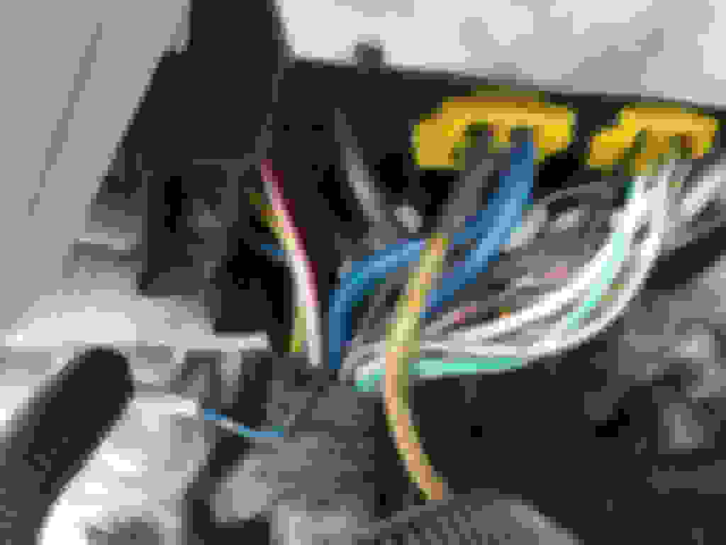
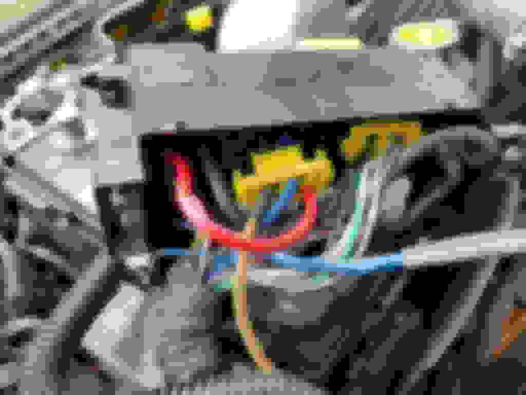
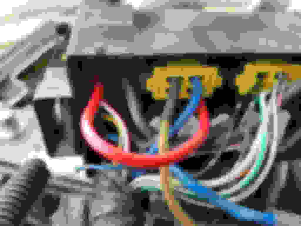
So the big blue wire that feeds the relay - -
This is a pic from above with the wire pulled out of the relay socket. You do NOT need to pull it out, just strip the tape back enough to cut the wire back with length to reach to the fuse block.
Crimp on the fuse female terminal, put it in the block like above, there you go.
These are commonly available at any parts store. Crimp a ring terminal on one end and attach it to the 10mm stud that has the main power wire to the fuse block. Cut the blue wire in the fuse block and use a butt crimp to attach it to the relay end of the wire.
With both, make sure to wrap with tape or heat shrink the loose cut end of the wire since this will still be a live circuit.
Dale
So 10mm stud >> fuse >> blue wire going into the relay
and tape/heatshrink off the harness side of the blue wire