When you click on links to various merchants on this site and make a purchase, this can result in this site earning a commission. Affiliate programs and affiliations include, but are not limited to, the eBay Partner Network.
No bigger pump needed for failure. That was on my stock fuel pump. I wouldn't even bother with a connector - it just maintains another potential failure point. There are perfectly suitable nylon bodied wire thru fittings with gas/ethanol resistant elastomer seals such as the one sold by the fuel cell company ATL that I listed.
Do you think poor OEM grounding could have contributed to the burned out plug in your car? I found that the stock ground point for the fuel pump in my 95 had developed some resistance, and cleaning up the this ground resulted in about a half volt increase in voltage at the fuel pump with no other change.
Do you think poor OEM grounding could have contributed to the burned out plug in your car? I found that the stock ground point for the fuel pump in my 95 had developed some resistance, and cleaning up the this ground resulted in about a half volt increase in voltage at the fuel pump with no other change.
In order for the connector to get burned out like that it would have to have been because a short developed in the connector or the fuse failed to blow and too much power was sent through the line. It could also be a combination of both. So either the connectors structural integrity was compromised d/t wear and tear or chemical breakdown allowing contact between the positive and negative wires/pins creating a short, and/or conductive debris built up inside the connector allowing heat to develop leading to the same outcome, and/or d/t a faulty fuse too much power flowed through the wire and heating it up which also leads to the same outcome.
OK, wired up my buddy's fuel pump today (and actually started his car, HALLELUJAH!!)
First off the terminals I linked to earlier in the thread WILL NOT WORK. Well, you can MAKE them work but they aren't the right ones. I had to cut some of the extra tabs off with a Dremel.
Second, there was a big step missed - there is a locking tab for the fuse terminals that needs to be pulled out to insert the new terminal. If you are getting it in there without doing so I have NO idea how you're doing it.
Pictures -
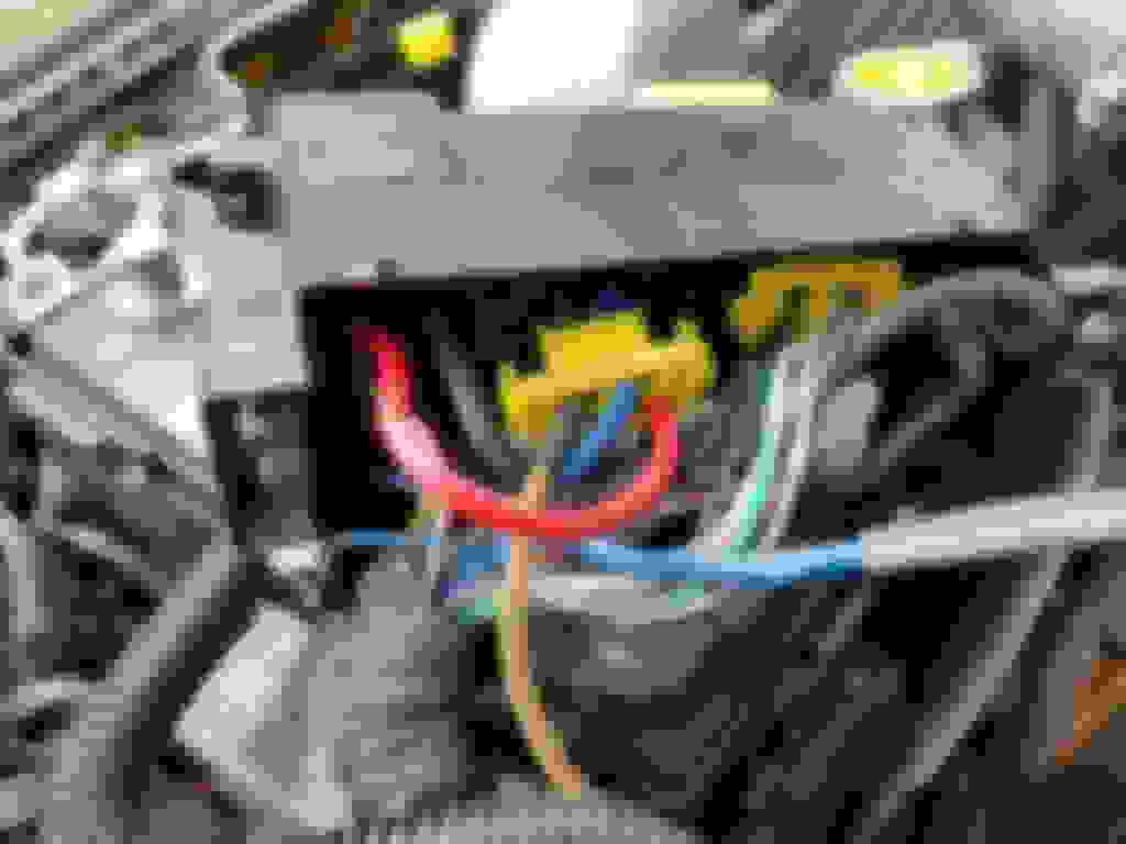
My connector (gold) versus an OEM connector pulled out of a spare fuse block -
This is the locking tab that slides out of the side of the fuse block. It comes out easily, just get the tip of a knife or something in there to pop it loose and it slides right out. It retains all the fuse terminals in the block.
If you look at the gold colored connector, that's the one I bought. There's a lot of extra tabs just behind where the fuse "touches", that had to come off to make it fit. That's where the plastic lock slides through.
I'll need to look around to find another source for those connectors (unless someone else finds one first!)
But, that said, I just cut the blue wire back, crimped that end on, cut off the extra tabs with a Dremel, and put it in the fuse block. Also discovered my new crimpers are kind of crap.
OK, wired up my buddy's fuel pump today (and actually started his car, HALLELUJAH!!)
First off the terminals I linked to earlier in the thread WILL NOT WORK. Well, you can MAKE them work but they aren't the right ones. I had to cut some of the extra tabs off with a Dremel.
Second, there was a big step missed - there is a locking tab for the fuse terminals that needs to be pulled out to insert the new terminal. If you are getting it in there without doing so I have NO idea how you're doing it.
Pictures -
My connector (gold) versus an OEM connector pulled out of a spare fuse block -
This is the locking tab that slides out of the side of the fuse block. It comes out easily, just get the tip of a knife or something in there to pop it loose and it slides right out. It retains all the fuse terminals in the block.
Hey Dale,
I didn't remove the locking cabinet for the fuse block when I inserted the terminal but it did take some convincing from the bottom and top with some precision flat head screw drivers. The plastic rention pin needs to be pushed back as you insert the terminal otherwise it gets in the way. Pulling out the locking cabinet would probably have required less convincing on my half but it did not prevent me from getting it in. The metal tabs that stick out i folded inward. Your terminal does look a bit fatter but nothing a little grinding couldn't fix. Your crimper could definitely be better, lol. Try cycleterminal.com for the fuse block terminals or searching for the Audi fuse block terminals. Those appear to he identical to the factory terminals.
-groovin
Last edited by sonicgroove; Mar 17, 2018 at 09:08 PM.
Cool. I would say that anyone else doing this would definitely want to remove that lock - it comes out super easy and gives you LOTS more room to work with.
Do you think poor OEM grounding could have contributed to the burned out plug in your car? I found that the stock ground point for the fuel pump in my 95 had developed some resistance, and cleaning up the this ground resulted in about a half volt increase in voltage at the fuel pump with no other change.
I do not believe it was the ground. I tested the ground of the FP circuit between the hatch connector and another earth and it registered no resistance.
Originally Posted by sonicgroove
In order for the connector to get burned out like that it would have to have been because a short developed in the connector or the fuse failed to blow and too much power was sent through the line. It could also be a combination of both. So either the connectors structural integrity was compromised d/t wear and tear or chemical breakdown allowing contact between the positive and negative wires/pins creating a short, and/or conductive debris built up inside the connector allowing heat to develop leading to the same outcome, and/or d/t a faulty fuse too much power flowed through the wire and heating it up which also leads to the same outcome.
-groovin
A short would blow the fuse. A short would also cause the fuel pump to stop functioning as the current flowed thru the short instead of the pump windings. None of those two things happened.
For the connector to melt all that has to happen is one of the connector terminals develops a condition that causes resistance. Doesn't matter what that condition is - all you need is resistance. Nothing has to be wrong with the fuse...
Say your stock pump is pulling 5 amps. That leaves another 5 amps of current on a 10 amp fuse before it blows. How much heat can that excess amperage generate? Power=Voltage*Current or P=VI or 60W=12V*5A...
60W, you know... like a light bulb in your house. Those get really hot and they are fairly well ventilated. In the above scenario you can generate 60W of heat inside your insulated connector and the fuse won't even blow. That's probably what melted the connector.
All that is beside the point... if you want a robust fuel system, the in-tank pump connector and hanger should either be replaced with factory new or bypassed.
Will a 12gauge be fine ? I tried with a 10gauge and it was too thick having hard time through the yellow retainer clip on top of that with the heatshrink it was a pita
I'm in the process of doing this rewire soon. I have located what I believe to be the correct ATC terminal. I have yet to use them, but I did manage to open them up for comparison purposes, and they look identical to the factory terminal. Click on the link and they'll be the Sumitomo Single Blade style. Cheers!
Will a 12gauge be fine ? I tried with a 10gauge and it was too thick having hard time through the yellow retainer clip on top of that with the heatshrink it was a pita
will a 12gauge be less efficient than 10gauge?
It is probably a wash. Use mil spec wire if you're worried. What kind of wire were you using?
I'm in the process of doing this rewire soon. I have located what I believe to be the correct ATC terminal. I have yet to use them, but I did manage to open them up for comparison purposes, and they look identical to the factory terminal. Click on the link and they'll be the Sumitomo Single Blade style. Cheers!
Thanks a lot to you SonicGroove for this post. (and Dale for the original tip)
I really did appreciate the photos, they help a lot (particularly when English isn't your first language ^^)
So I did the rewire, it took me a couple hours still, I struggled a lot trying to clip the fuse pin in place... (thanks again Dale for the photo of the fuse locker drawer , it took me 30sec when I knew this detail ^^)
the voltage at the pump was 7,9V before, and now it is 8,6V. And 12V with speed relay on, which is totally OK for my needs.
Also, I printed and added a small sticker on the box to make this clear in the future
if anyone is interested, I attach it to this post, the dimensions included in the file (15mm x 8mm )
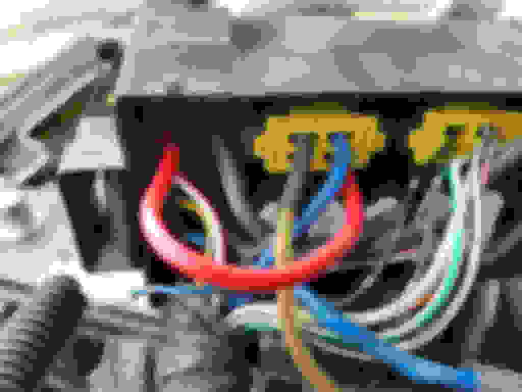
Thanks for posting this. Is there any trick to removing the yellow retaining locks that hold the relay pins? Mine is a bit stubborn, I've pushed in the two latches on the sides which lets it slides easily a few millimeters but then there is resistance again. Does anyone have photos of the yellow retaining lock completely removed from the housing?
Fuel pump relay rewire mod - yellow retaining lock question
By the way good call on the Sumitomo fuse terminals, I bought the ones labeled as 'ATC Female Terminal Strip 12-14AWG' from CycleTerminal and they look like an exact match. I'll post part numbers and comparison photos once I have the relay terminals swapped also.
Last edited by scotty305; Oct 8, 2020 at 02:32 AM.
I don't really remember if I struggled removing them too or not, but here are a couple photos, I hope that they'd help
But I do remember it was a PITA putting them back in place, the thin yellow plastic legs are not easy to put right in there...
This has worked well on my car, thanks to all who posted the info.
I used about 6 inches of very nice blue 12AWG wire from Prowireusa, the shipping costs more than the wire for such a short length. https://prowireusa.com/p-416-m22759-...el-12-awg.aspx
Their 10AWG wire would probably have fit since the tefzel insulation is very thin, but the terminals I found (below) claim they are designed for 12AWG and I didn't want to risk bad crimps. According to my math, voltage drop for six inches of 12 AWG wire carrying 15A current is only 0.015V which is already very good. Voltage drop for 10 AWG would be 0.009V which is a little better but not needed IMHO.
I think this may have been posted already, but Cycle Terminal has connectors that fit perfectly for both the fuse side and the relay side.
For the fuse side, 1qty of 'Sumi ATC 12-14 Female' near the bottom of this page: ATC/ATO 5 Circuit Bussed Fuse Box
For the relay side, at least 1qty of 'FST 1214N' near the bottom of this page: HD-250 Connectors
I got a few because they're inexpensive and sometimes it's helpful to do a test crimp on a spare length of wire.
My car has a mostly-stock engine with a standalone ECU and a fuel pressure sensor. Aftermarket injectors but stock fuel pump and otherwise-stock fuel pump wiring, the only mod related to the fuel pump is this little 6-inch length of wire. Per the advice of Aaron from Injector Dynamics I've been running about 50psi base fuel pressure because the fuel spray pattern should be nicer than it would at the stock 36psi base pressure. Datalogs have been showing that my stock pump and wiring doesn't maintain 50psi base pressure, but my ECU is configured to detect and compensate when fuel pressure drops and the measured AFR doesn't do anything scary. It's still nice to see the improvement, before this mod the pressure difference (fuel pressure - manifold pressure) would drop to about 35psi and after the wiring mod the pressure difference is only dropping to about 45psi.
The stock wiring would probably be fine for stock power levels at the stock fuel pressure, but not much more. I'd like enough headroom to run E85 occasionally, but I'm not sure that will be possible on the stock fuel pump even if I drop the base pressure down to 35-40psi.
I also bought crimpers from CycleTerminal, I think they cost around $30. I have a little spare wire and terminals, I could put together one or maybe two 'kits' if anyone is confident they can de-pin the original parts but doesn't want to spend the extra $30 buying another crimp tool.
Now look at the top of the fuse box and take note of the female terminal positions for the open circuit relay. Place the other end of the wire you just created in the location the previous blue wire was removed from. This end should also lock in place.
Line up the open circuit relay wires and reinstall the yellow retention clip. There are eight legs that go in a specific way. Make sure to line them up and guide them in with the fine precision jewelers flat head screw driver as you push the clip back in place. Organize the wires and reinstall the fuse box�s bottom covers ensuring all four clips snap in place.
Place the fuse box back on its mounting location. Make sure the side connected to the metal bracket snaps in place. Reinstall the 10mm nut to secure the fuse box. Place the black power cord back and secure with the previously remove 10mm nut as well. Reinstall the open circuit relay. Install the 20amp atc fuse in the 2nd to last slot with the 10awg black power wire and your newly installed 10awg blue wire. Reconnect the negative battery terminal and start the car to confirm the pump is working.
Hope this is helpful for those who are interested. Thank you again to the RX7club community.
-groovin
Am I crazy or are the 15 and 20 amp fuses switched? My lid tells me they should be placed opposite.
I've had the rewire done for almost 10 years now and I'm currently running two pumps but thinking about simplifying it and getting one Hellcat pump when I rebuild the fuel system (hopefully next year), mainly because I don't really NEED two pumps (I was trying to use one as a backup in case one failed), and I don't like that the fuel pumps have full voltage all the time that they don't need it. I don't suppose it would hurt anything doing this mod now and then changing back to a single pump in the future, right? I can't see why it would.
I don't remember if I read it but has someone seen the voltage at the pump at WOT with this mod?
Last edited by speedjunkie; Mar 26, 2022 at 10:53 PM.
I'm not sure that would be enough of an increase lol. I don't remember what I was getting at the pump but I remember some people seeing as low as 6v at WOT. I was on the dyno and it plateaued at 300HP and I was built for 450-475. Maybe PWM is the way to go instead.