When you click on links to various merchants on this site and make a purchase, this can result in this site earning a commission. Affiliate programs and affiliations include, but are not limited to, the eBay Partner Network.
I read that Chuck advised to change these cells on the INJ MAP instead of turning off O2 Feedback. I've seen him post several times about adjusting N3-N8 / P4-P7, but I have never seen his map to compare.
What direction does he recommend adjusting these 1.0 values? Up or down?
Do you recommend changing these values to eliminate the cruise surging?
Or do you recommend changing the cells that use the O2 feedback? What cells would those be?
Is this a series of hypothetical questions or do you have an exact scenario with a car that you are trying to address? Surging can occur under a number of scenarios for a number of different reasons. For example, surging can occur at idle on hot start and can often be addressed through changing the IAT compensation--something that is not accessible with a Commander. Surging can occur from idle system related issues. People have different definitions of the term "surging" anyway. Displaying data from the Datalogit software is the best way to investigate the problem; that kind of method is mostly beyond the scope of this thread.
As far as the O2 feedback goes, the conventional method is to turn it off and not deal with it at all. An alternative method which a few have explored is to keep it enabled while being mindful of the exact cells in which you are using it. I know that sounds vague but in a lot of cases it's easier to play around with this using the Datalogit software. The tuning notes contain a writeup that I did with significant assistance from one of the group members who did a lot of testing. It's not really a topic to address extensively in this thread.
to sum up my last post:
- I'm referring to the surges while cruising.
- light load, low rpm.
- Chuck said the cruising surges are caused by O2 feedback for specified INJMAP rows and columns.
-Apparently Chuck recommends adjustments to the values outlined on ARGHX's picture of the INJ MAP.
-nothing to do with idling. NO IDLE PROBLEMS. Idles perfect.
in response to arghx's post:
- those questions are directed at arghx mostly, or anyone else that has dealt with the cruising surge issue.
- cruising any gear, ~1800 to 3600 rpm, light load (Vac to 2psi)
- engine's power delivery surges either up or down.
- engine surges causing the car to lightly pitch back and forth.
- i am now curious as to how many other definitions of engine surges could there be.
I am certain that adjusting the cells used for O2 feedback on the INJ MAP isn't any more difficult than adjusting the IGT MAP.
I read that you should use Map Trace to confirm what cells are being used by O2 feedback, then adjust those cells accordingly. ARGHX's picture of INJ MAP already highlights those cells in question.
All I am asking is do I enrich or lean out those cells to get better performance from the O2 Feedback.
I think this could be a reliability mod considering it can be done with the Commander and it fixes the lean spikes caused by O2 Feedback in this region.
If i am mistaken, and the solution requires more than just an adjustment to INJ MAP, please provide the Tuning Notes link. I am having trouble finding it
Last edited by nismosilvia270r; Jan 13, 2012 at 04:59 PM.
in response to arghx's post:
- those questions are directed at arghx mostly, or anyone else that has dealt with the cruising surge issue.
- cruising any gear, ~1800 to 3600 rpm, light load (Vac to 2psi)
That's a big range actually, especially considering a lot of maps try to richen the mixture significantly right at 0psi.
- engine's power delivery surges either up or down.
- engine surges causing the car to lightly pitch back and forth.
- i am now curious as to how many other definitions of engine surges could there be.
Without actual quantifiable data, surging under the conditions you describe could most likely be caused by a lean mixture or in some situations a need for more ignition timing advance. The lean mixture could be a tip-in or sensor issue. It could be a temperature-related issue that requires IAT and water temp compensation. It could be something related to O2 feedback maybe. Or maybe not. You won't even know if you are in O2 feedback without seeing the waveform... o2 feedback is typically characterized by a sinusoidal narrowband sensor reading with "sawtooth" injector pulsewidth curves.
I am certain that adjusting the cells used for O2 feedback on the INJ MAP isn't any more difficult than adjusting the IGT MAP.
I read that you should use Map Trace to confirm what cells are being used by O2 feedback, then adjust those cells accordingly. ARGHX's picture of INJ MAP already highlights those cells in question. All I am asking is do I enrich or lean out those cells to get better performance from the O2 Feedback.
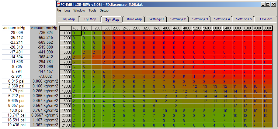
Probably neither. There's some theory behind the O2 feedback, INJ map, and base map that isn't covered in depth in this thread. Generally speaking, o2 feedback is either completely OFF (turned off in function select) or ON in select cells. The default cells in the default Apex'i map are in that box from the screenshot above. Those cells have O2 feedback enabled because their INJ value is between 1.00 and 1.047. 1.047 is not an arbitrary number; that number can be adjusted in the settings 1 tab of the Datalogit FC-Edit software. 1.00 isn't an arbitrary number either--I'll spare you the full technical explanation though (the concept of theoretical pulsewidth and the way it relates to the Power FC). The most common approach is to just turn O2 feedback off, but I have done some limited exploration of the o2 feedback with the help of others on this forum.
I think this could be a reliability mod considering it can be done with the Commander and it fixes the lean spikes caused by O2 Feedback in this region. If i am mistaken, and the solution requires more than just an adjustment to INJ MAP,
You are partly right about a type of solution, but you may not be right about the nature of the problem. What I mean by that is a surging issue can be caused by multiple things. One of Chuck's main points about O2 feedback can occur when someone does a certain process called a "recalc" inside the Datalogit FC-Edit software, something that is commonly done to overcome some limitations. This relates back to the larger theory behind the INJ map, base map, and O2 feedback.
There's more to the issue than meets the eye is all I'm saying. It's not as straightforward as it seems. Except in narrow circumstances, when you have a driveability issue somebody has to take a bunch of data to get to the bottom of it, especially when we are talking about things in an abstract sense over the internet.
please provide the Tuning Notes link. I am having trouble finding it
great. good info. I think I will try to "close the gap" between the 1.000 in the cells and the 1.047 in the feedback.
Since the cells affected by the o2 feedback are well below 1.047, perhaps ill lower the feedback value and slightly increase the INJ MAP cells. This may flatten the sinusoidal corrections.
My car is stock with intake and downpipe, so i wont be messing with too many things in the pfc.
So far the pfc has given me much more confidence in the stock seq system and boost control.
When O2 feedback is on (the default condition on a default PFC map):
IF the value in the INJ map cell is between 1.00 and 1.047 , O2 feedback will be ON in a given cell. Changing the values of the INJ map to a value anywhere between 1.00 and 1.047 has a good chance of having no real-world effect, since the PFC is taking over fuel injection anyway.
IF the value in the cell is below 1.00 or above 1.047, the O2 feedback is OFF. The PFC will not automatically make changes to the final injector pulsewidth in response to voltage measured from the stock narrowband.
there are a number of other factors which affect the final decision whether the O2 feedback is active in a given cell or not, such as water temperature, throttle position, and some interpolation effects between cells.
If you want to get in there and play around with it (changing stuff by feel) go ahead. Messing with the cells in question isn't going to break anything; in the worse case scenario it will run worse, but you can always revert back to what you had before. It would be much easier if you had a Datalogit interface with wideband o2 data acquisition however.
I have personally never used the pressure sensor voltage (boost-based as opposed to rpm-based) fuel enrichment map in the diagram above. But I will say that according to my Datalogit logs, 10psi is a little less than 4 volts on the default MAP sensor calibration. So if you want to ramp up enrichment when it hits near full boost, you could try something like this:
Absolutly incredible source of information. Unfortunitly i feel like a 4th grader reading a pregraduate's thesis paper, in another language, and im blind.
Thanks for all your hard work and dedication. I need to bone up on my terminology and acronyms. I also sent you a pm.
Great thread, thank you for posting this. I'm about to install my PFC for the first time and this will be a terrific asset.
If you ever plan to come down to NoVA to do some training do let me know. I'm well above my head with all of this stuff right now but very interested in learning more. Have only ever tuned a piggyback before.
Absolutly incredible source of information. Unfortunitly i feel like a 4th grader reading a pregraduate's thesis paper, in another language, and im blind.
Thanks for all your hard work and dedication. I need to bone up on my terminology and acronyms. I also sent you a pm.
Read it a few times over it helps to have the commander or datalogic hooked up , so you can understand and use a reference even just hte tunning software helps alot
Thanks. Ill be installing mine today. I have everything printed off and a few forum members on standby. This site has been an unbelievable wealth of information and confidence.
My car seems to have a slight "hot start issue". If the car sits for say 20 minutes or so it is slow to turn over and fights to hold itself for 10 seconds or so then idles fine.
My car seems to have a slight "hot start issue". If the car sits for say 20 minutes or so it is slow to turn over and fights to hold itself for 10 seconds or so then idles fine.
this may just be a bad battery , or going alternator . look at the Voltage
Yes that will work assuming your boost doesn't climb too high. This is really a temporary measure until it gets a real tune.
thanks for the reassurance
i did up the fuel via pim voltage instead of rpm per your instruction.
my boost so far is about 0.76 on the pfc commander with out any stock map sensor recalibration.
Apologies, I am relatively new to the Forums so I do not mean to step all over another thread and ask questions on what may be a new topic. I have a 93 FD that has been converted from street to track-complete engine modification and build by Banzai. The instrument cluster (Tachometer Primarily) was not working so I pulled the cluster and sent it off to Atlanta Speedometer for rebuild. Upon return the re-installed cluster worked for about 10 minutes and then reverted to old form-not working. I had followed information in the forum from George (Gen2n3) and worked with him (still working with him) to track down wires and leads before going back after the circuit board on the speedo for additional repairs. It turns out that our final wire from pin 2B on the Apexi leading to pin 3F on the connector at the back of the cluster has been cut and spliced into another connector at that point (at the clip that ties into the Cluster-not at the power fc unit). One of my homework assignments by George was to determine exactly what that pin 2B controls coming out of the Power FC. Are you able to offer any insight here. I would be most appreciative.
Fuel and emissions control system of the service manual will tell you, because the pinout of a Power FC is mostly the same as a stock ECU. It's page F-151 in the 94 workshop manual that's available online. Foxed.ca - Mazda RX-7 Manuals
So if you dig into it, you'll see it goes to the data link connector, the OBD 1 terminal for the factory service tool. You can download the Service Highlights document to explain the diagnostic connector better, page F-76. The pin is also in the wiring diagrams, page Z-30, where it shows it branching off to the tach. I think it's the tach signal wire labeled "IG-" in the diagrams.
This is extremely relevant to me, and thank you for doing my homework for me Arghx. I have my haltech DPO1 wired to pin 2B for tacho 2pulses, 12v Pullup and have no tachometer. I too sent my cluster in for repair of the odometer and the tach had been working after it was returned, but is no longer working after the haltech install. All other gauges work as intended.
There's some interesting information here, although it's not great information. It's more like "I touched this wire to this lead and it magically started working", but I may give it a shot as I'm running out of Ideas: https://www.rx7club.com/interior-ext...epair-1055763/
To answer your question directly John and follow up with what fixed my problem:
The problem for me is somewhere in the X-15 or X-07 connector. I had no continuity from ECU Plug 1M and cluster plug 3E G/R (VSS output from cluster to ECU) or ECU 2B to cluster 3F L/Y (Tachometer). Looking back at one of the data logs I realized I wasn't getting VSS in the haltech either. So I ran two wires from the haltech directly to 3E for VSS and 3F for Tacho and all is working now without running any wires directly to the cluster screws on PCB like some of the threads on the club recommend (DO NOT DO THIS).
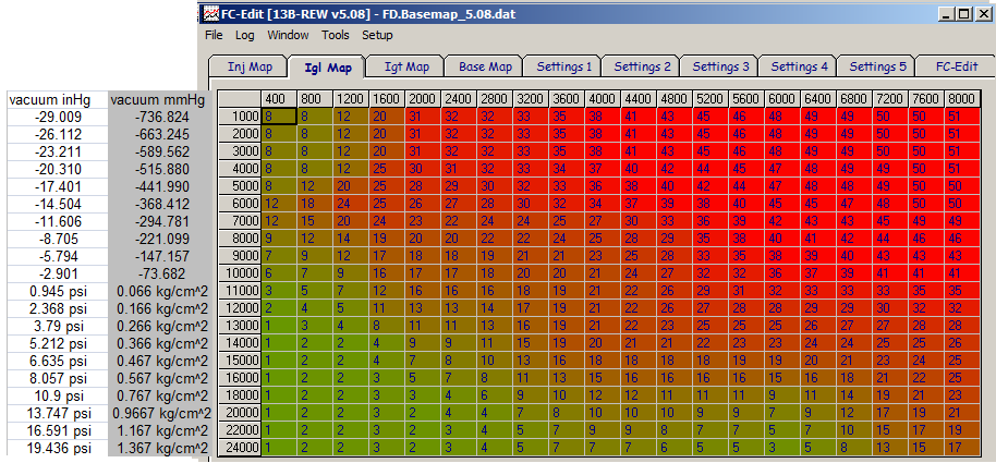
The PFC maps use absolute pressure in kg/cm^2, which is a pretty unusual. Most other engine management systems using absolute pressure will use kilopascals. Here are some of the default timing maps that come with the PFC but converted into relative pressure:
That's from PFC version 5.08 which is what most PFC's come with.
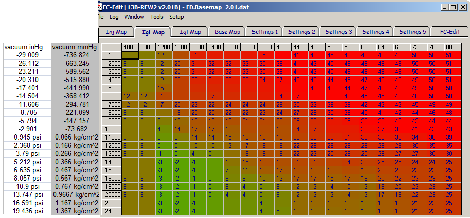
That's from an early version of the PFC, 2.08
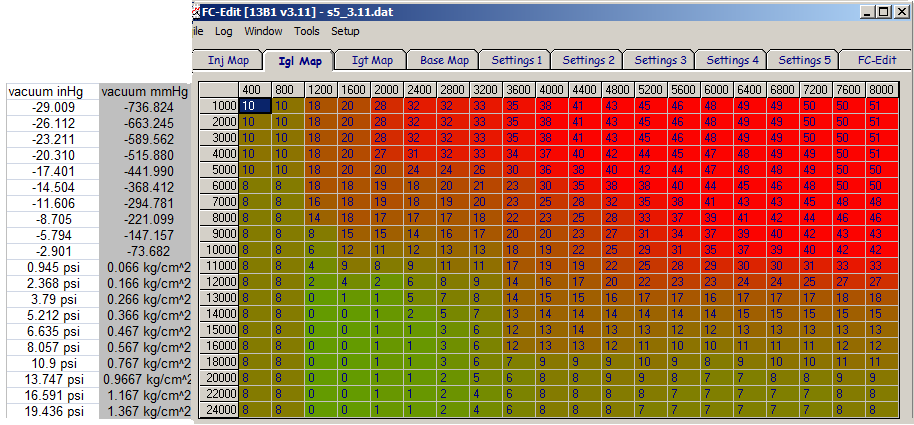
That's from the version for the FC series 5 Turbo.
The trailing/split maps that came with the PFC are kinda ugly, but here are a couple:
that's the regular 5.08 trailing/split map that most PFC's come with, the one I recommended you add split to.
The above split map from early PFC's, version 2.08, is better in terms of safety but it does have that weird spot at 7600 rpm.
These maps don't show the reference labels (N1, P1 etc) Remember that the PFC counts horizonally and vertically from the origin in the upper left corner. So the upper left corner is N1, P1 and the bottom right corner is N20, P20. Also keep in mind that your actual pressure readings will depend on the MAP sensor scaling and your altitude. The stock FD MAP sensor with the default calibration tends to read pressure a little bit low, usually about 1psi low by full boost.
For completeness, here also the timing maps taken off a new S8 PFC. PN 414BZ006


