
having trouble controlling sequential turbos with haltech

Thread Starter
Joined: May 2004
Posts: 2,991
Likes: 17
From: Charleston, SC
having trouble controlling sequential turbos with haltech
so i am trying to control stock sequential turbos with a single RPM-switched PWM output from a haltech PS1000. I want to set it up so that below the set RPM, only the primary turbo will boost, above that I want to switch everything so that both turbos will boost. For simplicity (and lack of PWM outputs), i wont be bothering with the factory prespool operation, just primary turbo on or both turbos on. As i understand, here is how the factory actuators work..
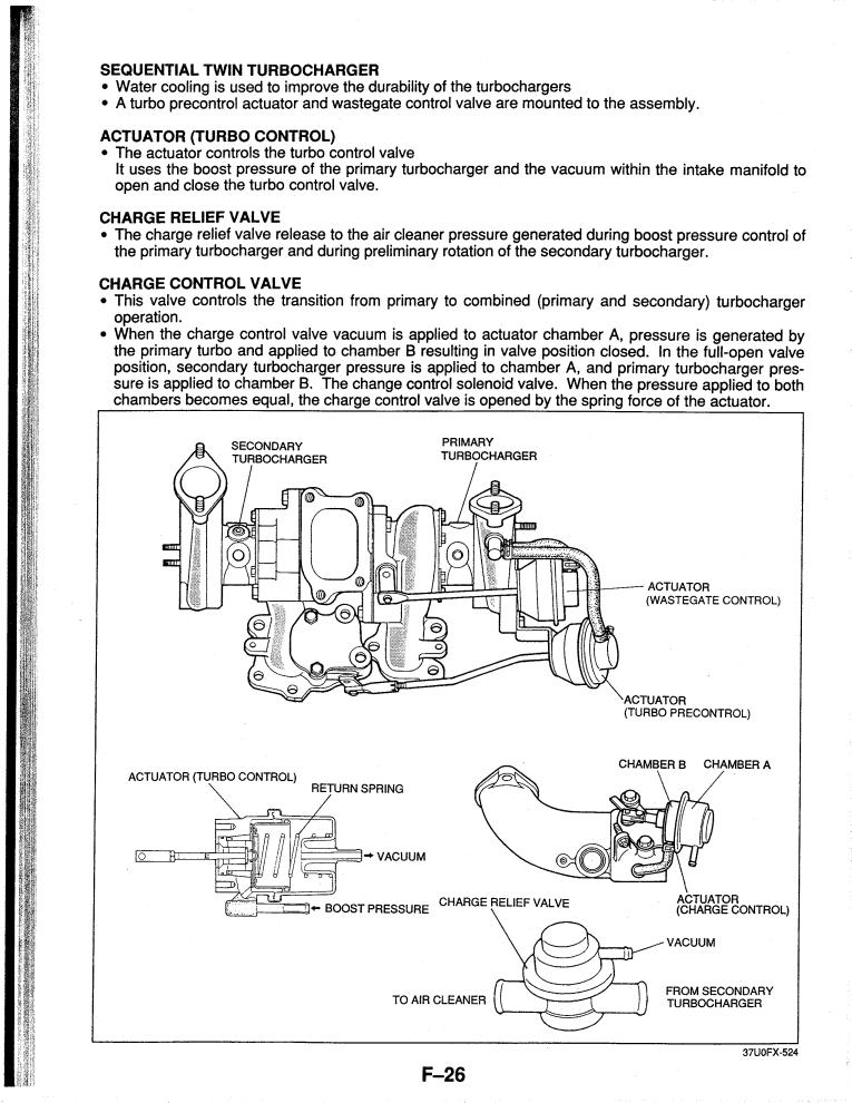
1. Turbo Control Actuator.. shuts off exhaust flow to 2nd turbo (actuator normally open, pulls closed)
2. Charge Control Actuator.. shuts off 2nd turbo compressor output from intake (actuator normally open, pulls closed)
3. Turbo Prespool Actuator.. allows small amount of exhaust flow to 2nd turbo (actuator normally closed, pushes open)
Below the set RPM, the Turbo Control Actuator needs to be closed, the Charge Control Actuator needs to be closed, and the Turbo Prespool Actuator needs to be closed. Above set RPM, everything opens up, allowing exhaust flow to both turbos and both compressor outlets to the intake.
Here is I have it setup..

The problem is below the set RPM, it will not build much boost, only like 2psi. as soon as it crosses the set RPM, it starts boosting like normal. I have tested the check valve with a vacuum pump, so i know that part works. what am i doing wrong? im about to rip this **** out and go single
1. Turbo Control Actuator.. shuts off exhaust flow to 2nd turbo (actuator normally open, pulls closed)
2. Charge Control Actuator.. shuts off 2nd turbo compressor output from intake (actuator normally open, pulls closed)
3. Turbo Prespool Actuator.. allows small amount of exhaust flow to 2nd turbo (actuator normally closed, pushes open)
Below the set RPM, the Turbo Control Actuator needs to be closed, the Charge Control Actuator needs to be closed, and the Turbo Prespool Actuator needs to be closed. Above set RPM, everything opens up, allowing exhaust flow to both turbos and both compressor outlets to the intake.
Here is I have it setup..
The problem is below the set RPM, it will not build much boost, only like 2psi. as soon as it crosses the set RPM, it starts boosting like normal. I have tested the check valve with a vacuum pump, so i know that part works. what am i doing wrong? im about to rip this **** out and go single


Are you running the stock pressure and vacuum tanks? The TCA in particular needs that reservoir of pressure and vacuum to actuate and actuate quickly.
Also, you don't have the Charge Relief Valve in there, that's the blow-off valve looking deal on the back of the Y-pipe. It vents pressure from the second turbo while it's spooling, then shuts when it's online.
You also may need to visually test to see if each component is moving on command. For example, the charge control valve butterfly should be shut at low RPM and open after sequential switchover, same for the turbo control actuator.
The "prespool actuator" most of us don't run separately. With a boost controller, you T the boost controller's output to the wastegate and precontrol actuators. Doesn't seem logical but it works.
Dale
Dale's got this right.
You also need the Charge Relieve Valve to release the pressure. Sorry I dont know much about the Haltech, otherwise I couldve been helpful =P.
-AzEKnightz
You've got some things mixed up. I have written extensively about the sequential system:
https://www.rx7club.com/3rd-generation-specific-1993-2002-16/why-engine-so-damn-complicated-part-1-sequential-turbos-demystified-841821/
https://www.rx7club.com/3rd-generation-specific-1993-2002-16/comparison-rx-7-13b-rew-supra-2jz-gte-sequential-turbos-960727/
I even proposed one way to set it up on an FC:
https://www.rx7club.com/2nd-generation-specific-1986-1992-17/those-you-considering-sequential-fd-twin-turbos-904199/
You can also PM me for further documentation.
Now let's get down to your system. You are a bit mixed up on how things work.
The actuator is normally closed. Vacuum and boost push it open quickly. The whole point of the pressure chamber is to serve as an accumulator of sorts so that the valve opens quickly. On the stock system, separate solenoids control vacuum and boost. They are both switched at the same time from the same pin of the stock ECU. If you really want to you could try skipping the pressure chamber and just use a check valve or something. It could affect turbo transition. With your current setup you are assuming that the charge control and turbo control work the same way, and they don't. Mazda designed it that way for a reason...
You are correct here. One side of the actuator gets primary turbo boost, the other goes to a 3-way solenoid. On the stock system, the NO port on the solenoid goes to boost (pretty sure it's not from the actual pressure chamber) and the NC port goes to vacuum from the vacuum chamber.
The turbo control and charge control are always in the opposite states. When one is ON the other is OFF. So you could use a relay on one or the other to change polarity if you are out of ECU outputs. Below the transition point the charge control solenoid is ON, switching vacuum to one side of the actuator. The turbo control solenoids are OFF. Then at the transition point it changes: charge control solenoid is OFF (opening the butterfly valve by releasing vacuum on one side of the actuator) while the turbo control output is ON opening the valve.
This is correct. Below the transition point this actuator is duty controlled. It is the primary means of controlling boost before transition. After transition it is fully opened (95% duty). On paper this is a superior design for keeping the valve fully open after transition. However, as Dale pointed out lots of guys have run with a single controller for both precontrol and wastegate. You could do that, or you could use a manual boost controller somewhere. I argue that the stock system is superior, even if it isn't totally "necessary," but you have to work within your constraints.
This should read:
"Below the set RPM, the Turbo Control Actuator is already closed, the Charge Control Actuator needs to be closed , and the Turbo Prespool Actuator needs to be duty controlled. Above set RPM, everything opens up, allowing exhaust flow to both turbos and both compressor outlets to the intake."
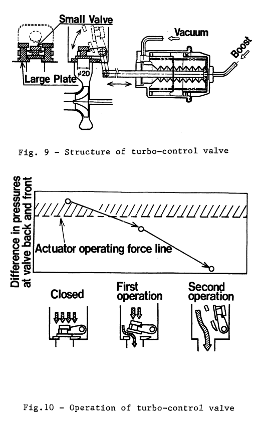
What it boils down more than anything else is that you are blowing open the turbo control valve. Study this diagram:
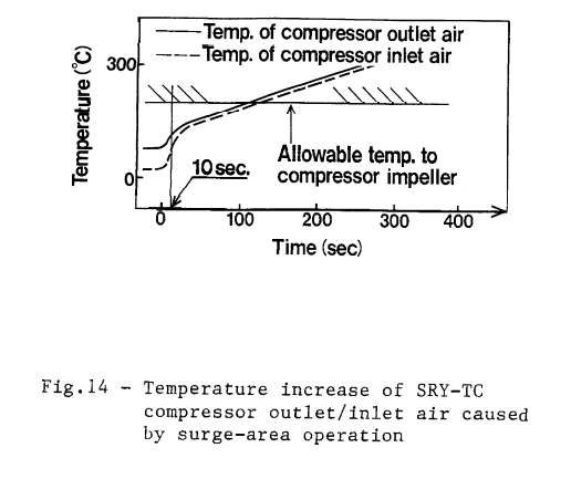
Given your constraints I bet you could get away without the charge relief valve. Supras don't have one and Mazda has tested the amount of time the primary turbo [on the 20B] could go into surge:
https://www.rx7club.com/3rd-generation-specific-1993-2002-16/why-engine-so-damn-complicated-part-1-sequential-turbos-demystified-841821/
https://www.rx7club.com/3rd-generation-specific-1993-2002-16/comparison-rx-7-13b-rew-supra-2jz-gte-sequential-turbos-960727/
I even proposed one way to set it up on an FC:
https://www.rx7club.com/2nd-generation-specific-1986-1992-17/those-you-considering-sequential-fd-twin-turbos-904199/
You can also PM me for further documentation.
Now let's get down to your system. You are a bit mixed up on how things work.
1. Turbo Control Actuator.. shuts off exhaust flow to 2nd turbo (actuator normally open, pulls closed)
2. Charge Control Actuator.. shuts off 2nd turbo compressor output from intake (actuator normally open, pulls closed)
The turbo control and charge control are always in the opposite states. When one is ON the other is OFF. So you could use a relay on one or the other to change polarity if you are out of ECU outputs. Below the transition point the charge control solenoid is ON, switching vacuum to one side of the actuator. The turbo control solenoids are OFF. Then at the transition point it changes: charge control solenoid is OFF (opening the butterfly valve by releasing vacuum on one side of the actuator) while the turbo control output is ON opening the valve.
3. Turbo Prespool Actuator.. allows small amount of exhaust flow to 2nd turbo (actuator normally closed, pushes open)
Below the set RPM, the Turbo Control Actuator needs to be closed, the Charge Control Actuator needs to be closed, and the Turbo Prespool Actuator needs to be closed. Above set RPM, everything opens up, allowing exhaust flow to both turbos and both compressor outlets to the intake.
"Below the set RPM, the Turbo Control Actuator is already closed, the Charge Control Actuator needs to be closed , and the Turbo Prespool Actuator needs to be duty controlled. Above set RPM, everything opens up, allowing exhaust flow to both turbos and both compressor outlets to the intake."
The problem is below the set RPM, it will not build much boost, only like 2psi. as soon as it crosses the set RPM, it starts boosting like normal. I have tested the check valve with a vacuum pump, so i know that part works. what am i doing wrong? im about to rip this **** out and go single
Given your constraints I bet you could get away without the charge relief valve. Supras don't have one and Mazda has tested the amount of time the primary turbo [on the 20B] could go into surge:
Thread Starter
Joined: May 2004
Posts: 2,991
Likes: 17
From: Charleston, SC
awesome info. I can add in the charge relief valve, i just have to feed it vacuum from the CCA. I will also loose the PSV solenoid and just feed it from the WG actuator
but Im still confused about the turbo control actuator. maybe im having a giant brain fart, but my turbo control actuator is definitely normally in the pushed-outward, toward rear of car position (exhaust port open). Ive crawled under the car and applied vacuum via a hand pump to the top port of this actuator, and the rod will pull toward the front of the car, which appears like it closes the port, according to Fig 9 above and ive also verified this on a spare set of twins.

closed (actuator pulling toward front of car)

open (actuator pushing toward rear of car)
my diagram puts vacuum on the top port of the TCA during primary turbo boost, and PRI boost to side port, which should keep it closed. or am i missing something? hell i can try hooking it up backwards and see what happens. i think i will definitely need to add a vacuum chamber to do that, because i do not think there is enough vacuum in the lines alone to move the actuator
but Im still confused about the turbo control actuator. maybe im having a giant brain fart, but my turbo control actuator is definitely normally in the pushed-outward, toward rear of car position (exhaust port open). Ive crawled under the car and applied vacuum via a hand pump to the top port of this actuator, and the rod will pull toward the front of the car, which appears like it closes the port, according to Fig 9 above and ive also verified this on a spare set of twins.
closed (actuator pulling toward front of car)
open (actuator pushing toward rear of car)
my diagram puts vacuum on the top port of the TCA during primary turbo boost, and PRI boost to side port, which should keep it closed. or am i missing something? hell i can try hooking it up backwards and see what happens. i think i will definitely need to add a vacuum chamber to do that, because i do not think there is enough vacuum in the lines alone to move the actuator
The actuator on the exhaust manifold that moves the TCA should be getting just atmospheric pressure on both nipples at idle/low load. When transition happens, both vacuum and boost hit the two nipples to smoothly and quickly open the door up.
If you are always applying vacuum, it will try to open it.
Dale
If you are always applying vacuum, it will try to open it.
Dale
I'll start by saying that I obviously don't have your vehicle in front of me and I've never tried hands-on to engineer a shortcut (if you'll excuse the term) to make the TCA work. What I do know is that it is a deceptively complicated design. You have vacuum, pressure, springs forces, a two-stage valve and exhaust pressure all working together. The exhaust pressure helps close the valve:
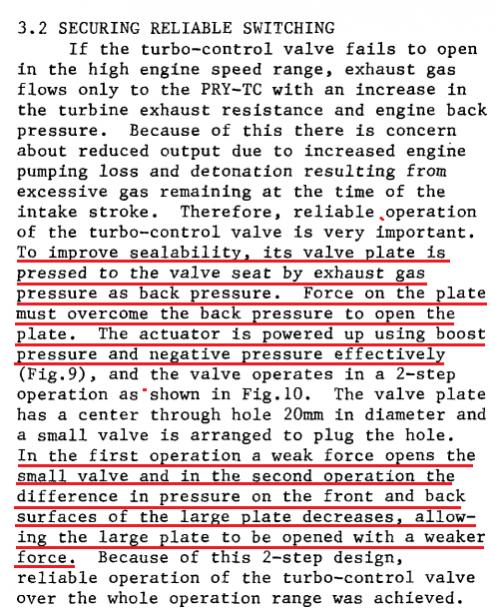
If you hook up good components and control it (pneumatically speaking) the way Mazda designed it will work.
If you hook up good components and control it (pneumatically speaking) the way Mazda designed it will work.
Trending Topics
Thread Starter
Joined: May 2004
Posts: 2,991
Likes: 17
From: Charleston, SC
so below 4000 RPM, the TCA needs to see no vacuum or boost to stay closed? Can you put vacuum on the side port to keep it closed?
After 4000 RPM, the TCA top port needs vacuum, side port needs boost, is that correct? that makes no sense to me but i will try it
After 4000 RPM, the TCA top port needs vacuum, side port needs boost, is that correct? that makes no sense to me but i will try it
Thread Starter
Joined: May 2004
Posts: 2,991
Likes: 17
From: Charleston, SC
ah i found the source of my confusion.. the spare manifold (pics above) is evidently not a 13B-REW, its actuator is turned 180 degrees out from mine. ok so vacuum at the top port and boost at the side port will open the TCA, got it. thanks for the help guys

That diagram looks better. It still doesn't have the same level of precise control as the stock system but you have limited ECU outputs. Normally the charge relief valve ("secondary BOV" in your diagram) is controlled independently from the charge control with its own rpm range of operation. On paper there should be a bigger boost drop during transition with your system as compared to a 100% stock system. But I can see your setup still getting the job done--again, you have to work within your constraints.
Give it a shot and report back.
Give it a shot and report back.
Thread Starter
Joined: May 2004
Posts: 2,991
Likes: 17
From: Charleston, SC
its better, but still doesnt boost very well, only about 2-3 psi below 4000 RPM. but i do not have the boost controller wired in yet
when i was testing it with a vacuum pump, I discovered the side port on the TCA does not hold vacuum? so i connected it to 2nd turbo compressor output, that way theoretically it sees atmosphere below 4000 rpm, and boost above 4000 rpm
when i was testing it with a vacuum pump, I discovered the side port on the TCA does not hold vacuum? so i connected it to 2nd turbo compressor output, that way theoretically it sees atmosphere below 4000 rpm, and boost above 4000 rpm

Thread
Thread Starter
Forum
Replies
Last Post
stickmantijuana
MoTeC
5
Sep 10, 2015 07:58 PM

