
Full nonsequential diagram

Thread Starter
Joined: Dec 2001
Posts: 505
Likes: 6
From: Los Angeles, CA
Full nonsequential diagram
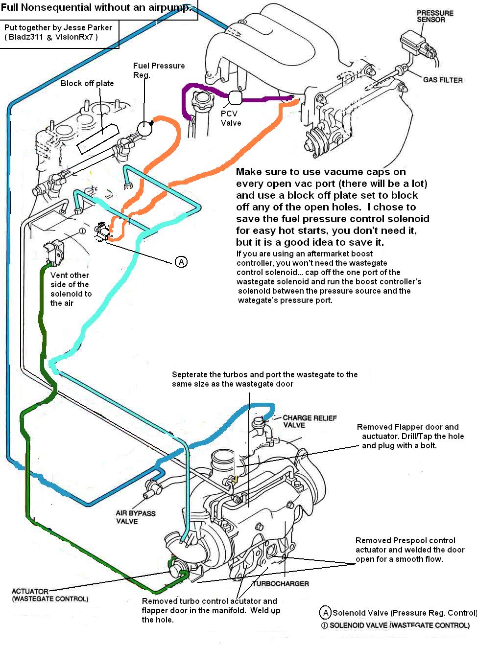
I got bored today, so I put this together. Give me some input on it. I thought this may help some people looking to do the mod. BTW.. it is highly recomened to not use your stock computer with this setup!...
Peace,
Jesse Parker
Peace,
Jesse Parker
Last edited by bladz311; Sep 2, 2006 at 05:09 PM.

so everything is almost the same except where the actuator goes to the wastegate control and the other diagram just relies on the actuator and not the solenoid. also what block off plates did you use. i just know about the avc and egr. is anything else blocked off?


Trending Topics
Thread Starter
Joined: Dec 2001
Posts: 505
Likes: 6
From: Los Angeles, CA
Sorry for the messy looking diagram, but its still easy to read.
I forget what size resistors I used. I will check today. If you are using a power fc or other stand alone, you won't need the resistors... I'm still on the stock ecu until my power fc comes in the mail, so I did use resistors for now.
I left the stock boost control solenoid just incase people would still want to control boost from it, but I wrote in the writeup how to use an aftermarket boost controller with this setup.
I used rx7store.net 's block off plates. I got rid of my double throttles, acv, and the air pipes for the air pump... I didn't need to get rid of the egr since i have a jspec engine without one. Also, I got rid of the charcoal canister to clean up a little bit.
The diagram for the single turbo would be pretty close other than the turbos being changed and you probably won't be using the stock boost control solenoid.
Thread Starter
Joined: Dec 2001
Posts: 505
Likes: 6
From: Los Angeles, CA
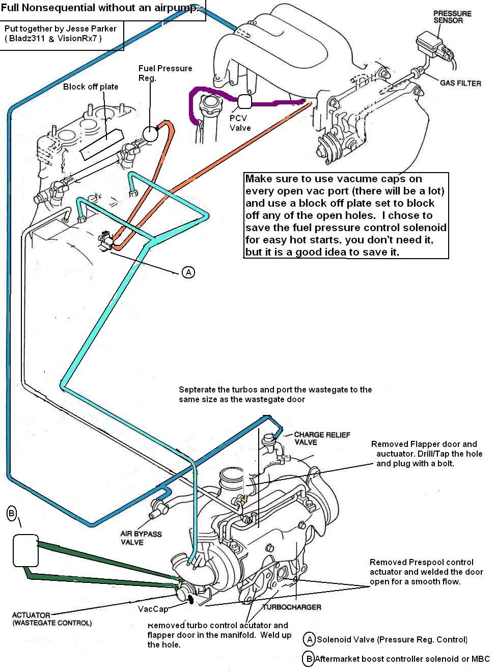
ok, I revised it a little... I noticed I called the wastegate actuator the wastegate solenoid, so I fixed that and redid the vac lines to clean up the drawing a little. Also, I added another diagram for an aftermarket boost controller...
Stock boost control solenoid...

Aftermarket boost controller...
Stock boost control solenoid...
Aftermarket boost controller...
Last edited by bladz311; Sep 3, 2006 at 01:39 PM.


ok, I revised it a little... I noticed I called the wastegate actuator the wastegate solenoid, so I fixed that and redid the vac lines to clean up the drawing a little. Also, I added another diagram for an aftermarket boost controller...
Stock boost control solenoid...
Aftermarket boost controller...
Stock boost control solenoid...
Aftermarket boost controller...

Many have deleted the fuel pressure regular solenoid as well. Just run the vacuum line on the LIM to the FPR. I believe the oil injectors can be left without lines, as they don't need vacuum/boost, but I left mine anyways. I would leave a line from the oil filler neck to the primary turbo inlet. Just my $.02
Doesn't the boost control system need a vacuum source?
Doesn't the boost control system need a vacuum source?
What's your point ?
Joined: Feb 2001
Posts: 3,573
Likes: 0
From: Gainesville, Fla.
NOPE 10 psi with the same turbo's is still 10psi with the same turbos. The only difference is simplification of your turbo control system.

What's your point ?
Joined: Feb 2001
Posts: 3,573
Likes: 0
From: Gainesville, Fla.
Hey guys...I was talking about the second diagram where he has the manual boost controller installed on the wastegate actuator. How exactly is it hooked up and do I still need the restrictor pill in the line while the manual boost controller is attatched to make it function properly? Also where are those light cyan blue lines coming from and do I have to "T" them together?

Thread
Thread Starter
Forum
Replies
Last Post
Adaptronic 1280s Hot Start 3 Rotor 20b RX7
Monsterbox
Adaptronic Engine Mgmt - AUS
5
Sep 11, 2015 03:29 PM
msilvia
3rd Generation Specific (1993-2002)
15
Sep 11, 2015 12:13 PM
240sx, apexi, boost, controller, coolant, diagram, diy, evans, fd, full, nonsequential, radiator, rx7, sequential, sr20det