
Fuel system upgrade how to - write up for KGparts kit.


Fuel system upgrade how to - write up for KGparts kit.
Ok, so here is my attempt at a comprehensive fuel system upgrade writeup. I need to thank Keith, Steve, and Shawn for helping me a lot in this process.
This writeup will be based on upgrading the primary and secondary rails and injectors, as well as SS braided line for everything in the engine bay to the firewall. My upgrade uses a kit from KGParts.
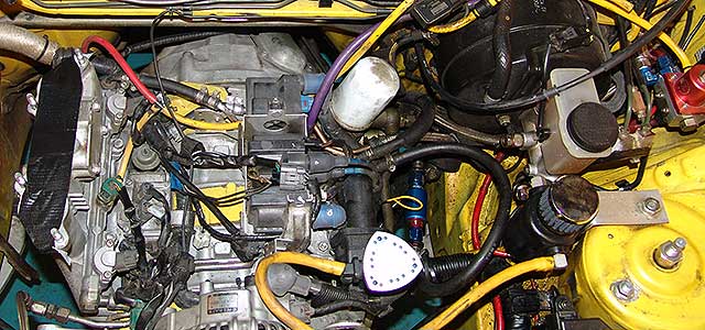
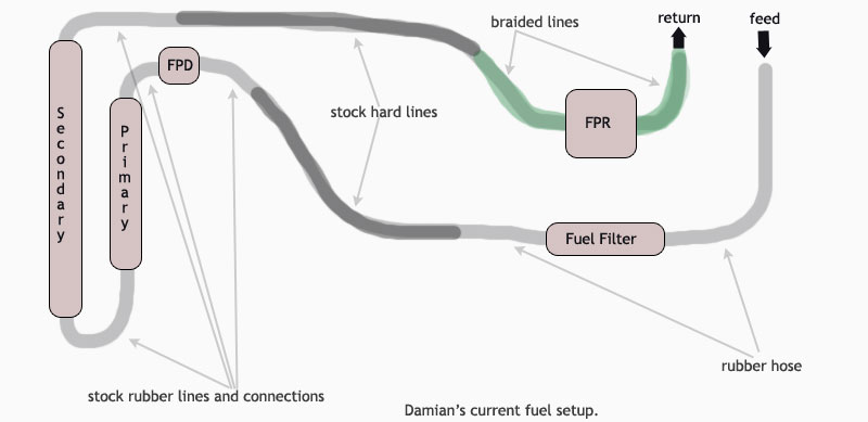
First lets start by looking at my system before the upgrade, as you will see I already had an aftermarket FPR and the fuel filter was moved up here from the rear.
Here is a drawing to better see how it was:
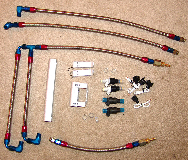
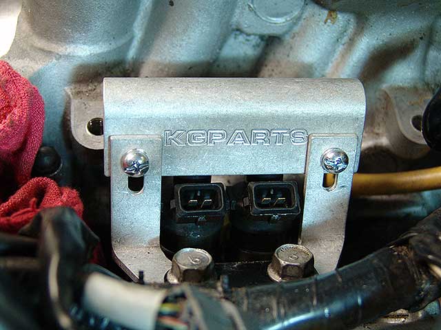
Here is a picture of the new kit from KGParts:
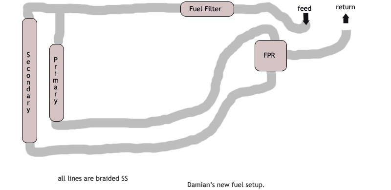
The new kit runs a bit differently, the rails are not in series like the stock system, they are in parallel, so they both get their own feed from the main feed line and they get their own return to the FPR.
Here is a drawing of how I planned to run my new setup:
Summary Of Install
1) relieve gas pressure (search forums, there is plenty of info on how to do this)
2) remove all old rails/injectors/lines
keep some towels around as there will be gas in the rails/lines and you want to place towels under these areas before disconnecting. Not a big deal as it evaporates fast anyway. I let a lot dump around and it was gone in minutes.
3) before installing anything, lay it out on the engine where its supposed to go, including the lines. This helps you plan if you need to change line lengths or use different fittings to make the lines go where you want them without kinking them up. This step saved me a lot of trouble in determining the FPR placement and fuel filter placement and what was needed to make both happen correctly.
4) Washed out the rails and checked all the holes for 'hangnails' that could be filed off. You dont want 'dirty rails' going in there :-)
5) Put the sleeves on the injectors, according to the info I got it was the shorter sleeves on the secondaries and the longer ones on the primaries. I also used a bit of motor oil to lube the injector 0-rings.
6) On the primaries, remove the stock diffuser and follow the process outlined below on using them as a seal for the injectors. on the secondaries pull out the old seal and diffuser. The injector install quirks are detailed below. I had to use things that looked like dentist tools in order to get the diffusers out without destroying them. YOU WANT TO KEEP THEM INTACT, YOU WILL END UP USING PART OF THEM.
7) Install the rails, lines, and whatever else you upgraded (fpr, gauge, et)
8) Setup your electrical connectors with the resistors, clip the old connectors and solder the new ones in. Apparently the resistor can go on either side and the connectors wires can go on either wire of the stock connector. Just keep track of what connector goes to what injector.
Those are the basics, here are pictures and details of certain aspects of the install.
This writeup will be based on upgrading the primary and secondary rails and injectors, as well as SS braided line for everything in the engine bay to the firewall. My upgrade uses a kit from KGParts.
First lets start by looking at my system before the upgrade, as you will see I already had an aftermarket FPR and the fuel filter was moved up here from the rear.
Here is a drawing to better see how it was:
Here is a picture of the new kit from KGParts:
The new kit runs a bit differently, the rails are not in series like the stock system, they are in parallel, so they both get their own feed from the main feed line and they get their own return to the FPR.
Here is a drawing of how I planned to run my new setup:
Summary Of Install
1) relieve gas pressure (search forums, there is plenty of info on how to do this)
2) remove all old rails/injectors/lines
keep some towels around as there will be gas in the rails/lines and you want to place towels under these areas before disconnecting. Not a big deal as it evaporates fast anyway. I let a lot dump around and it was gone in minutes.
3) before installing anything, lay it out on the engine where its supposed to go, including the lines. This helps you plan if you need to change line lengths or use different fittings to make the lines go where you want them without kinking them up. This step saved me a lot of trouble in determining the FPR placement and fuel filter placement and what was needed to make both happen correctly.
4) Washed out the rails and checked all the holes for 'hangnails' that could be filed off. You dont want 'dirty rails' going in there :-)
5) Put the sleeves on the injectors, according to the info I got it was the shorter sleeves on the secondaries and the longer ones on the primaries. I also used a bit of motor oil to lube the injector 0-rings.
6) On the primaries, remove the stock diffuser and follow the process outlined below on using them as a seal for the injectors. on the secondaries pull out the old seal and diffuser. The injector install quirks are detailed below. I had to use things that looked like dentist tools in order to get the diffusers out without destroying them. YOU WANT TO KEEP THEM INTACT, YOU WILL END UP USING PART OF THEM.
7) Install the rails, lines, and whatever else you upgraded (fpr, gauge, et)
8) Setup your electrical connectors with the resistors, clip the old connectors and solder the new ones in. Apparently the resistor can go on either side and the connectors wires can go on either wire of the stock connector. Just keep track of what connector goes to what injector.
Those are the basics, here are pictures and details of certain aspects of the install.
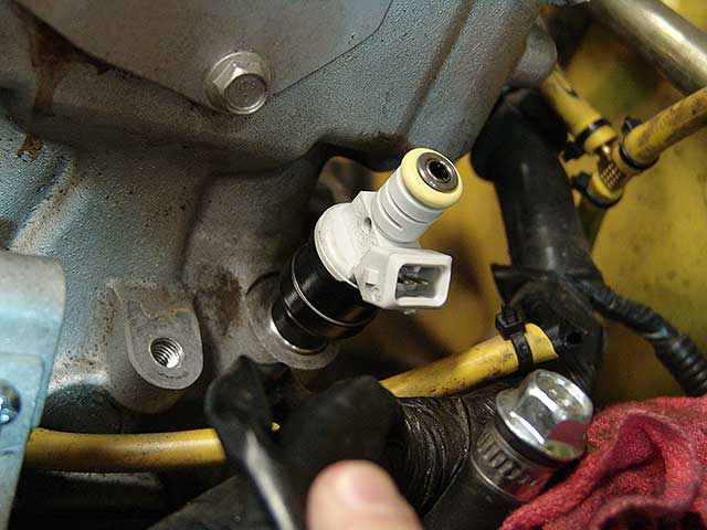
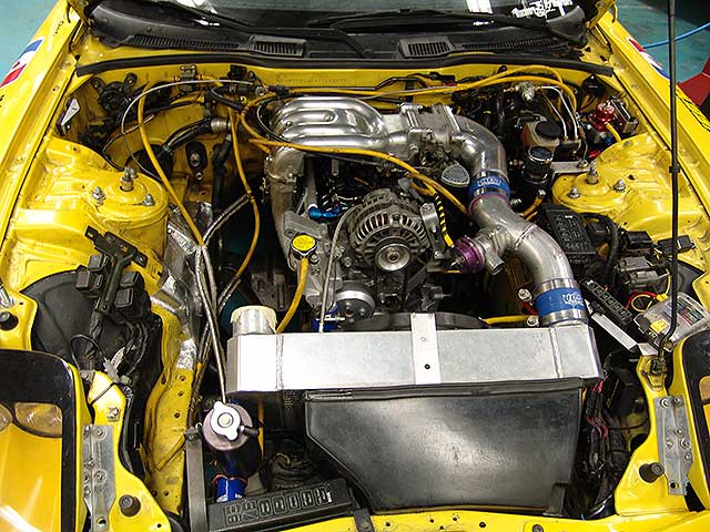
Primary Rail and Injectors
Here is what the primary rail and injectors looks like when its installed:
The install is not difficult, but be sure to read below on the seating/sealing of the injectors.
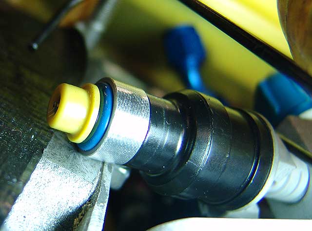
Secondary Rail and Injectors
Here is a picture of a secondary injectors seated:
The install is pretty straight forward and the injector should seal fine for the reasons described below.
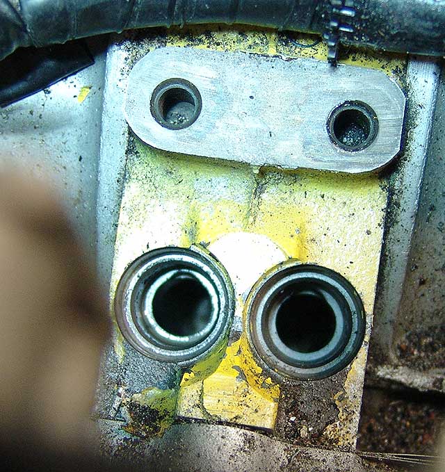
The Diffusers and Seating/Sealing The Injectors
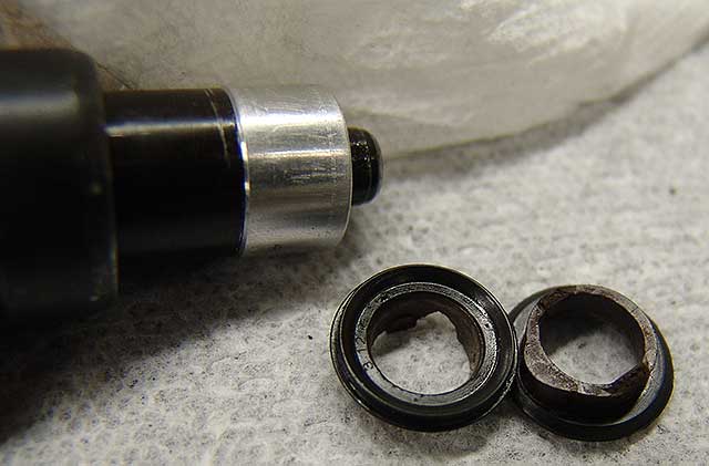
Ok, there are many ways to go on this but here is what I found and how I ended up dealing with the injectors seating/sealing issues. First of all the sleeves help the injectors seat properly, but it debatable if they actual 'seal' properly by them selves. Some have run only sleeves with no issues, some run sleeves and a small cut of fuel hose up on the injector body to make an external seal. I didnt like either of these options and wanted a seal similar to the stock style. The issue only involves the primary injectors as the secondaries seal fine because the o-ring ends up past the sleeve and it seats against the housing for a great seal.
Here is a picture showing what I mean, the secondary diffuser with sleeve on showing the o-ring protruding out the end:
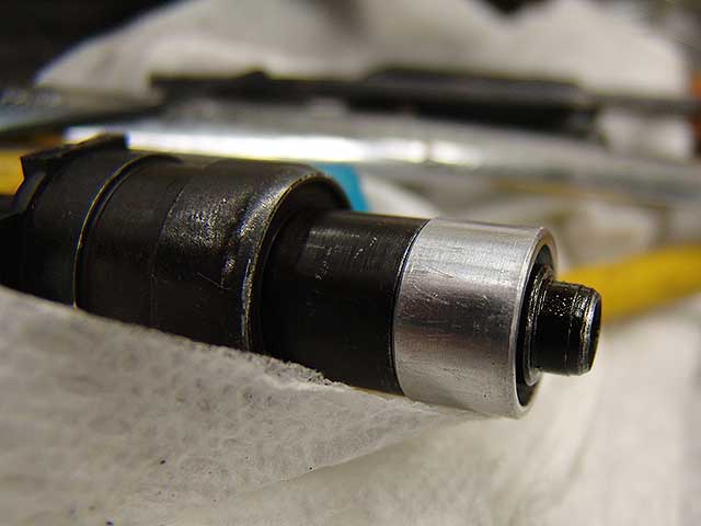
However, the primaries are not so fortunate, the sleeve passes farther than the o-ring, so when installed its the metal of the sleeve against the metal of the housing, with no rubber material sealing them. Now this may work as the sleeves are a very tight fit and it may seal, but I was not feeling good about it.
Here is the primary with the sleeve on, see how the o-ring is totally hidden:
Now, to toss another wrench in this entire deal, is the primary injector holes have a 'notch' at the bottom of them that matches a protrusion on the diffusers that go in there. Its meant to make the diffusers fit in the right way when installed. However it complicates trying to make a good seal with just a sleeve or trying to make your own rubber seal.
Here is a picture of the notches I am referring to:
So, to make a long story short, what I did was take the stock primary diffusers and cut the rubber seal that is integrated to the end of it, and then GENTLY bored out the inside of the hole in the diffuser just a bit so that the seal would hit the sleeve after the end of the injector went in the diffuser seal hole. If you do no do this then it will bottom out on the nose of the injector before hitting the sleeve and defeat the purpose as acting as a seal. Be VERY careful when you bose the hole out, it can crack easy an is usually pretty brittle.
Here are the primary diffusers with one modified as mentioned above:
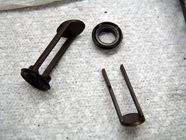
Here is the set with the holes bored out and ready to be used.
Doing this made a great seal. I started my car for the first time today after installing all this stuff (and all the other winter mods) and it started right up and there was no fuel leaks. Keep in mind I have not run the car in boost yet, I just idled the car, so it has not passed all the tests just yet.
Electrical Connections
There is many posts on if you should or should not use resistors and what ohm resistors, blah blah. Basically here is what I decided to do and why. After getting an education on the actual reasoning behind the resistors it all made sense to me (thanks mainly to steve kan for walking me through the math/physics on all this). From what I understand, the injector drivers on the pfc should not see more that 2 amps. So when you upgrade to the bigger injectors they are most likely lower impedance that the stock injectors. So what you have to do is make sure that there is enough resistance to keep the amps below 2 so you dont run the risk of burning out the injectors drivers. There is a lot of talk about 10 ohm, 6 ohm, and even 4 ohm...but i wanted to know WHY those numbers where being spouted, so after reading a great post by CCarlisi and getting help from steve I now understand. Here is the math (copied from CCarlisi post):
Since Amps=volts/resistance
12v/2.8ohms (bosch 160lb injectors) =4.29 amps without resistors
With 6ohm resistors
12v/2.8+6ohm resistor =1.36 amps
With 10ohm resistors
12v/12.8=.94 amps
Stock injectors
12v/13.8=.87 amps
Now, I measured the resistance on my primaries and they were around 4.5 ohms and the secondaries were 2.8 ohms.
So based on this math I decided to use 3.9 on the primaries and 5.6 on the secondaries. This made them both close to the 8 ohms range in total. Thus keeping my amps under the 2 marker.
And as far as watts go, many use 10 watt but I used 25 watt for the follwing reason (thanks to steve for the math):
12V/6ohm = 2Amps
2Amps * 12V = 24W
To my understanding the higher the watts the better it takes the heat. So I went with 25 to be on the safe side. These resistors were not easy to find locally, but eventually I found 2 online sources for getting these resistors:
http://www.weisd.com/store2/NTERES/NTE25WRESLIST1.html
http://marvac.com/default.aspx (search for resistors)
After I purchased mine I read this thread on some higher end resistors that you may want to use:
https://www.rx7club.com/forum/showth...light=resistor
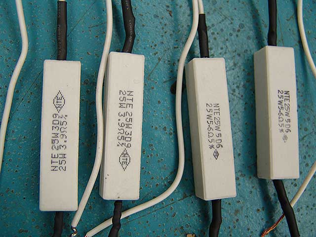
Here is a pic with them ready to go in:
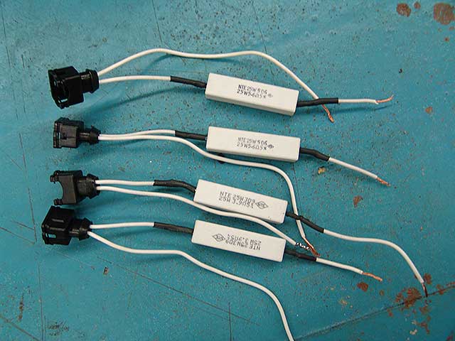
Close up of resistors:
FPR
I wanted this to stay where it was before, in the drivers side corner, so I had to 'edit' some of the braided lines in the kit. Basically I just had to make longer return lines, it was no big deal but braided line is a serious PIA to get fittings on unless you have the right tools and know a good way to do it. It took me a few attempts to get the process of cutting a line and getting a fitting on it, and I will talk about that in the next section. Here is a pic of my FPR and the bracket I made to hold it in place.
[img]http://www.myrx7.com/images/fuel_install_fpr_1.jpg" width="640" height="480" alt="" border="0">
Here is what the primary rail and injectors looks like when its installed:
The install is not difficult, but be sure to read below on the seating/sealing of the injectors.
Secondary Rail and Injectors
Here is a picture of a secondary injectors seated:
The install is pretty straight forward and the injector should seal fine for the reasons described below.
The Diffusers and Seating/Sealing The Injectors
Ok, there are many ways to go on this but here is what I found and how I ended up dealing with the injectors seating/sealing issues. First of all the sleeves help the injectors seat properly, but it debatable if they actual 'seal' properly by them selves. Some have run only sleeves with no issues, some run sleeves and a small cut of fuel hose up on the injector body to make an external seal. I didnt like either of these options and wanted a seal similar to the stock style. The issue only involves the primary injectors as the secondaries seal fine because the o-ring ends up past the sleeve and it seats against the housing for a great seal.
Here is a picture showing what I mean, the secondary diffuser with sleeve on showing the o-ring protruding out the end:
However, the primaries are not so fortunate, the sleeve passes farther than the o-ring, so when installed its the metal of the sleeve against the metal of the housing, with no rubber material sealing them. Now this may work as the sleeves are a very tight fit and it may seal, but I was not feeling good about it.
Here is the primary with the sleeve on, see how the o-ring is totally hidden:
Now, to toss another wrench in this entire deal, is the primary injector holes have a 'notch' at the bottom of them that matches a protrusion on the diffusers that go in there. Its meant to make the diffusers fit in the right way when installed. However it complicates trying to make a good seal with just a sleeve or trying to make your own rubber seal.
Here is a picture of the notches I am referring to:
So, to make a long story short, what I did was take the stock primary diffusers and cut the rubber seal that is integrated to the end of it, and then GENTLY bored out the inside of the hole in the diffuser just a bit so that the seal would hit the sleeve after the end of the injector went in the diffuser seal hole. If you do no do this then it will bottom out on the nose of the injector before hitting the sleeve and defeat the purpose as acting as a seal. Be VERY careful when you bose the hole out, it can crack easy an is usually pretty brittle.
Here are the primary diffusers with one modified as mentioned above:
Here is the set with the holes bored out and ready to be used.
Doing this made a great seal. I started my car for the first time today after installing all this stuff (and all the other winter mods) and it started right up and there was no fuel leaks. Keep in mind I have not run the car in boost yet, I just idled the car, so it has not passed all the tests just yet.
Electrical Connections
There is many posts on if you should or should not use resistors and what ohm resistors, blah blah. Basically here is what I decided to do and why. After getting an education on the actual reasoning behind the resistors it all made sense to me (thanks mainly to steve kan for walking me through the math/physics on all this). From what I understand, the injector drivers on the pfc should not see more that 2 amps. So when you upgrade to the bigger injectors they are most likely lower impedance that the stock injectors. So what you have to do is make sure that there is enough resistance to keep the amps below 2 so you dont run the risk of burning out the injectors drivers. There is a lot of talk about 10 ohm, 6 ohm, and even 4 ohm...but i wanted to know WHY those numbers where being spouted, so after reading a great post by CCarlisi and getting help from steve I now understand. Here is the math (copied from CCarlisi post):
Since Amps=volts/resistance
12v/2.8ohms (bosch 160lb injectors) =4.29 amps without resistors
With 6ohm resistors
12v/2.8+6ohm resistor =1.36 amps
With 10ohm resistors
12v/12.8=.94 amps
Stock injectors
12v/13.8=.87 amps
Now, I measured the resistance on my primaries and they were around 4.5 ohms and the secondaries were 2.8 ohms.
So based on this math I decided to use 3.9 on the primaries and 5.6 on the secondaries. This made them both close to the 8 ohms range in total. Thus keeping my amps under the 2 marker.
And as far as watts go, many use 10 watt but I used 25 watt for the follwing reason (thanks to steve for the math):
12V/6ohm = 2Amps
2Amps * 12V = 24W
To my understanding the higher the watts the better it takes the heat. So I went with 25 to be on the safe side. These resistors were not easy to find locally, but eventually I found 2 online sources for getting these resistors:
http://www.weisd.com/store2/NTERES/NTE25WRESLIST1.html
http://marvac.com/default.aspx (search for resistors)
After I purchased mine I read this thread on some higher end resistors that you may want to use:
https://www.rx7club.com/forum/showth...light=resistor
Here is a pic with them ready to go in:
Close up of resistors:
FPR
I wanted this to stay where it was before, in the drivers side corner, so I had to 'edit' some of the braided lines in the kit. Basically I just had to make longer return lines, it was no big deal but braided line is a serious PIA to get fittings on unless you have the right tools and know a good way to do it. It took me a few attempts to get the process of cutting a line and getting a fitting on it, and I will talk about that in the next section. Here is a pic of my FPR and the bracket I made to hold it in place.
[img]http://www.myrx7.com/images/fuel_install_fpr_1.jpg" width="640" height="480" alt="" border="0">
Braided Lines
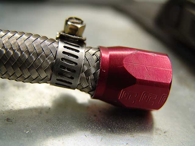
This is just a tip on how I used a small screw-clamp as my tool to get the ned fittings on without flaring out all the braids and making it impossible to get the fittings on. Basically I tightened the clamp where I wanted to cut the line and cut it right to the edge of the clamp. Then pushed the clamp back just a bit so there is some hose that can enter the fitting.
Here is a pic with the clamp pushed back a bit after the cut:
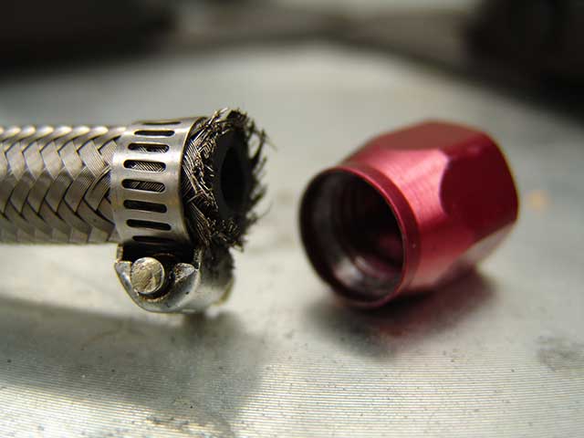
Keep the clamp on and tight enough to hold the braided line from flaring out, but loose enough so that it slides down the hose as you push the fitting on:
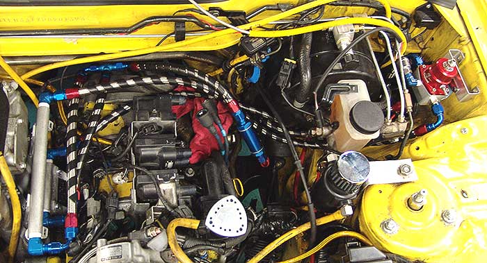
Below is a shot of my final setup. Notice how I wrapped the braided lines in that black spiral 'stuff'. Its meant to eliminate the situation where braided lines wear away things that they rub against. I also zip-tied them where i could to eliminate any possibility of braided lines vibrating around, everything is pretty tight and moves as one unit.
Basically once you put all the goodies back on the car you cant really see much.
Good luck!!!
This is just a tip on how I used a small screw-clamp as my tool to get the ned fittings on without flaring out all the braids and making it impossible to get the fittings on. Basically I tightened the clamp where I wanted to cut the line and cut it right to the edge of the clamp. Then pushed the clamp back just a bit so there is some hose that can enter the fitting.
Here is a pic with the clamp pushed back a bit after the cut:
Keep the clamp on and tight enough to hold the braided line from flaring out, but loose enough so that it slides down the hose as you push the fitting on:
Below is a shot of my final setup. Notice how I wrapped the braided lines in that black spiral 'stuff'. Its meant to eliminate the situation where braided lines wear away things that they rub against. I also zip-tied them where i could to eliminate any possibility of braided lines vibrating around, everything is pretty tight and moves as one unit.
Basically once you put all the goodies back on the car you cant really see much.
Good luck!!!

NYC's Loudest FD
Joined: Mar 2001
Posts: 1,539
Likes: 1
From: Long Island, NY
Damian, just to let you know this is not the proper way to run 4 low impedience injectors on a PFC. There are 2 problems with this setup, #1 The response of the injectors will slow down considerably enough that even if you adjust the acceleration times for the injectors on the PFC it's not going to be enough to compensate, #2 If you plan to run high boost you'll have a problem with the injectors closing and opening properly with the added boost pressure. These 2 things happen when you use resistors. When you add resistors you're reducing the power output slighty to these injectors. The proper way to have done this without effecting the response time and strength of the injectors would have been to use a specified injector driver for the injectors you're using. FJO makes an excellent driver(s) for this application, you should consider using this instead of resistors, here's the info on it:
FJO Racing Products is very pleased to offer a stand-alone low impedance injector driver. This product allows the use of low impedance injectors with ECUs designed for high impedance injectors only.
The LOW IMPEDANCE INJECTOR DRIVER accurately reproduces the ECU�s injector pulses in a PEAK & HOLD format and is compatible with full sequential, phase sequential, and batch fired injector pulses. There are no special set-up requirements and it installs easily between the ECU and injectors. This product can be used singly or in multiples for any number of cylinders or injector channels.
The LOW IMPEDANCE INJECTOR DRIVER is built for the racing environment to withstand heat, vibration, dirt and water. It is designed to operate over the temperature range from -40 to +185 degrees Fahrenheit (-40 to +85 degrees Celsius).
FEATURES
4 independent injector channels with input preloaded to 200 ohms
Allows use of low impedance injectors on ECUs designed for high impedance injectors only, no need to replace OEM ECU
Reproduces ECU injector pulses in PEAK & HOLD format (4A/1A)
Supports full sequential, phase sequential, and batch fired injector pulses
No special set-up required
Can be used in multiples for 6, 8, 10, and 12 cylinder applications
BENEFITS
Easy to install, installs between ECU and Injectors
Built for the racing environment to withstand heat, vibration, dirt and water
Free direct technical support
Last edited by Mahjik; Mar 13, 2005 at 12:31 PM.
Damain looks great. I just got a couple questions... You only used the seal for the diffuser and not the actual diffuser itself correct? Also a better way to cut and attach the AN fittings is to actually wrap some fillament tape around the line a few times and cut it straight with a cutoff wheel. That works the best for me anyway. But great writeup on the upgrade, nice pics 
Trending Topics

Originally Posted by HDP
In your layout drawings, aren't the primary and secondary rails switched? Good write up BTW.
ahh yes, u are right...i will corerct them
Originally Posted by RX794
Damian, just to let you know this is not the proper way to run 4 low impedience injectors on a PFC. There are 2 problems with this setup, #1 The response of the injectors will slow down considerably enough that even if you adjust the acceleration times for the injectors on the PFC it's not going to be enough to compensate, #2 If you plan to run high boost you'll have a problem with the injectors closing and opening properly with the added boost pressure. These 2 things happen when you use resistors. When you add resistors you're reducing the power output slighty to these injectors. The proper way to have done this without effecting the response time and strength of the injectors would have been to use a specified injector driver for the injectors you're using. FJO makes an excellent driver(s) for this application, you should consider using this instead of resistors, here's the info on it:
(snip)
(snip)
Originally Posted by G's 3rd Gen
Damian u r now running 850's and 1680's correct? Or r the 2nds 1600's.Thanks G...
Originally Posted by Scrub
Damain looks great. I just got a couple questions... You only used the seal for the diffuser and not the actual diffuser itself correct? Also a better way to cut and attach the AN fittings is to actually wrap some fillament tape around the line a few times and cut it straight with a cutoff wheel. That works the best for me anyway. But great writeup on the upgrade, nice pics
yes, i should have clarified, you have to cut off the bottom part of the primary diffusers, you only use the top 'seal' part, but cut it low enough that it has the bump that fits the notch in the housing.
on the line, yeah, the tape is the way to go, just didnt have any access to that kind of tape at the time, so had to do the clamp thing, and yea, i used a cutoff wheel to cut the line.

Rotary Enthusiast
Joined: Feb 2001
Posts: 1,094
Likes: 0
From: Orange County, CA
Originally Posted by damian
here is somthing im curious about, the pfc commander only let me move the sec injectors to 1500...i wonder if the datalogic allows for a higher value?
you also may want to consider a fuel pusation damper...I just got one from marren for like $114, it's an aftermarket one.
http://www.injector.com/fueldampers.php
I know a lot of people say you don't need it, but I'd rather not worry about running lean due to fuel getting sloshed around in the rails.
http://www.injector.com/fueldampers.php
I know a lot of people say you don't need it, but I'd rather not worry about running lean due to fuel getting sloshed around in the rails.


glad to help, be sure to follow all the other posts in here as some had great suggestions to improve the setup. according to the previous owners post, my track car uses a RP Hi Flow fuel pump:
https://www.rx7club.com/showthread.p...hreadid=211166
https://www.rx7club.com/showthread.p...hreadid=211166