Electron Manipulation

 01-10-07, 10:58 PM
#102
development
Thread Starter
Back Working on the Silver FD
I was out doing some install work on my car and wanted to share...
Some of the great things about this 37 pin "quick disconnect" connector on my main engine harness is the fact, I don't have to remove interior pieces to remove my engine, I don't have to hassle with the harness firewall boot ever again, I don't have to remove the UIM to remove my engine, it's extremely easy to remove from the motor (in the car or out), and it has "room to grow".
It's been two years since I built this harness and modifing has turned out to be very easy...you can see 6 loops toward the right of the harness. I used them to pass my 3 (yes 3) EGT's thru the firewall and bring the signals to the gauge and the monitor (WB, boost, & EGT datalogger).
I just added 6 wires to the harness, and still have 6+ available for modifications (I didn't count all of them...just know I have the other ends of the loops available plus more). Passing wires thru the firewall for items that will be removed/installed on the motor has never been cleaner or easier.
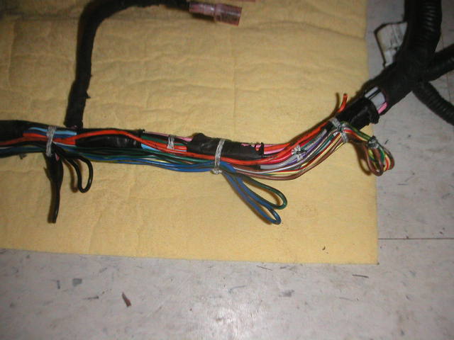
I just have to cut these loops, tie in, and find the same color on the ECU side and splice the other end of the added wires (one side of the loop goes into the ECU for a controlled function, and the other side is a pigtail ready for modification!). IE:
Rear Rotor EGT
BR (+)
BR/W (-)
Front Rotor EGT
L/Y (+)
Y/R (-)
Final EGT
G/B (+)
G/R (-)
The little yellow connector will go back into the end of the DP, so I can monitor the EGT going into my metallic cat. Since I run emissions, I don't want to cook my cat.

you can see the leads (unsleeved runs) in the picture, the two long ones are for my exhaust runners...so I can tune aggressively with the use of AI.
here is a gauge/probes I picked up from Pineapple Racing.

Still having fun...
Some of the great things about this 37 pin "quick disconnect" connector on my main engine harness is the fact, I don't have to remove interior pieces to remove my engine, I don't have to hassle with the harness firewall boot ever again, I don't have to remove the UIM to remove my engine, it's extremely easy to remove from the motor (in the car or out), and it has "room to grow".
It's been two years since I built this harness and modifing has turned out to be very easy...you can see 6 loops toward the right of the harness. I used them to pass my 3 (yes 3) EGT's thru the firewall and bring the signals to the gauge and the monitor (WB, boost, & EGT datalogger).
I just added 6 wires to the harness, and still have 6+ available for modifications (I didn't count all of them...just know I have the other ends of the loops available plus more). Passing wires thru the firewall for items that will be removed/installed on the motor has never been cleaner or easier.
I just have to cut these loops, tie in, and find the same color on the ECU side and splice the other end of the added wires (one side of the loop goes into the ECU for a controlled function, and the other side is a pigtail ready for modification!). IE:
Rear Rotor EGT
BR (+)
BR/W (-)
Front Rotor EGT
L/Y (+)
Y/R (-)
Final EGT
G/B (+)
G/R (-)
The little yellow connector will go back into the end of the DP, so I can monitor the EGT going into my metallic cat. Since I run emissions, I don't want to cook my cat.
you can see the leads (unsleeved runs) in the picture, the two long ones are for my exhaust runners...so I can tune aggressively with the use of AI.
here is a gauge/probes I picked up from Pineapple Racing.
Still having fun...

 01-11-07, 10:30 AM
#104
Looks very nice. Where did you learn about wiring? I think I've seen you mention aircraft work before.
PS, while working on a recent project (not RX-7 related) I found some VERY small automotive relays that are rated up to 25A. They're solder-on connectors (designed to be mounted on a circuit board), but the weight/packaging savings is pretty incredible. PM me if you want more info.
-s-
PS, while working on a recent project (not RX-7 related) I found some VERY small automotive relays that are rated up to 25A. They're solder-on connectors (designed to be mounted on a circuit board), but the weight/packaging savings is pretty incredible. PM me if you want more info.
-s-
01-11-07, 10:49 AM
#105
development
Thread Starter
I've been messing around with wiring since I was a kid...then got a degree in electrical engineering...then worked for Lockheed Martin. Since I was there, figured I'd take the training courses that the union workers take...you know, to "better my understanding of electronics" 
I am now certified in installation, modification, and repair of aircraft electrical wiring systems; including: Data Bus Termination Assembly & Installation, Testing Electrical Bonds, Terminal Stake Power Tools, and Fiber Optic Fabrication and installation
I was fortunate to have samples of lots of robust components (connector assembly included)...I figured, if jets can travel MACH 2.5 at 50,000+ ft, it should work in my FD.
01-12-07, 08:30 AM
#109
development
Thread Starter
Originally Posted by Marcel Burkett
What kind of tape / insullation is that ? i've been looking for something similar to redo part of my oem harness ?
take a stock brand new harness to be used for a single and a PFC
~$750 -OEM harness
~$65 -connector
~$35 - backshells
~$300 - pins/sockets
Then if I do the work for $50 (which I'm not about to do), you are looking at a total cost of $1200 for a harness (I believe MoToC sells one for $1600-$1800).
Then where do they mount it? My 1995 ABS is smaller and allowed for the room, go look at some pics of 93-94 ABS systems...
Not much of a market for that...or money in it for me.
Originally Posted by Marcel Burkett
What kind of tape / insullation is that ? i've been looking for something similar to redo part of my oem harness ?
http://cableorganizer.com/Bentley-Ha...do-fr-plus.htm
01-23-07, 07:49 AM
#112
development
Thread Starter
^yes, that's what it is...but that's not my car...I did the design/fab work though. The thing I really like is, it will talk with the MoTeC; as I tried to show in one of the pictures. I can't comment on the performance, when I moved from ATL, the car never got touched again...plans are to fly in this summer and finish
thanks bud!
Originally Posted by KINETIK_FD3S
how did i miss this thread, nice work dubulup.
01-23-07, 02:00 PM
#114
MenWithGutsAttackCorners!

Join Date: Nov 2006
Location: bristol tn
Posts: 295
Likes: 0
Received 0 Likes
on
0 Posts
do you have a write up or anything on making the ic sprayer?
if so could you pm me the link
thanks either way i am jsut amaized by allthouse wiers/toggels/ect..
if so could you pm me the link
thanks either way i am jsut amaized by allthouse wiers/toggels/ect..
01-23-07, 02:42 PM
#115
development
Thread Starter
Originally Posted by vtakk eg
do you have a write up or anything on making the ic sprayer?
if so could you pm me the link
thanks either way i am jsut amaized by allthouse wiers/toggels/ect..
if so could you pm me the link
thanks either way i am jsut amaized by allthouse wiers/toggels/ect..
The rear reservoir now is my "reserve" 50:50 meth tank...and my old "IC spray" switch now refills my AI tank in the passenger bin


I guess now is as good of time as any to share some more wiring pictures. Pay no attention to my dirty car.
I'm a big fan of using stock wiring when possible. Since the Haltech now controls my fuel pump and air pump...the relays have been removed and used as jumper points to my Aux Injection Pump shown above) and my C4 Corvette electric air pump

here is the rewired fuel pump diagram...Also rewired per Dale Clarks thread for rewiring stock fuel pump https://www.rx7club.com/3rd-generation-specific-1993-2002-16/new-clubrx-rewire-your-fuel-pump-easy-cheap-reliability-mod-615964/
I pick up fuel pump power where the fuel pump resistor use to be and power my AI pump controller; which uses an internal MAP sensor to activate and increase AI pump pressure. More Boost = More AI

Since these wires go back to the hatch to feed the fuel pump, I just picked them up there and ran the connection to my passenger side storage bin.
The fuel pump speed relay now sends power to my AI safe injection module (when the controller gets a high enough boost reading from the UIM), which in turns sends the "alarm trigger" signal back down the chassis harness to my Haltech which switches fuel/ign maps and lowers boost...when the flow of 50:50 Meth/water isn't ideal for an aggressive tune.

Here is the diagram for those who can't picture what I've done to modify my stock two speed fuel pump system to control and monitor my Aux Injection system. All in All, I've probably added less than 36" of wire to the car...on a system that spans from my passenger bin, to under my cruise control, to the nose of the car, and to ECU.
 02-16-07, 10:51 AM
#116
Rotary Freak
Join Date: Nov 2001
Location: trinidad and tobago
Posts: 2,715
Likes: 0
Received 0 Likes
on
0 Posts
The spray bar I'm using , https://www.rx7club.com/auxiliary-injection-173/intercooler-spray-597441/
02-16-07, 11:08 AM
#117
development
Thread Starter
very nice! I never saw good results spraying my IC. Temps would drop a degree or 2F. Now with my dual oil coolers, I hope my radiator doesn't need to dump as much heat...in turn not heat soaking my IC as much; which will yield lower intake temps.
Crazy way to think about it...Oil cools the engine from the inside out, and coolant outside in, so better oil cooling means there won't be as much heat entering the coolant...but in theory it should work. rynberg uses the same IC I do with the same size oil cooler I've upgraded too...and he sees much much lower intake temps than I use too.
PS. Ever scroll down to the bottom of my thread and see this?

you all do know, that when this baby hits 88mph...we're going to see some serious ****!
Crazy way to think about it...Oil cools the engine from the inside out, and coolant outside in, so better oil cooling means there won't be as much heat entering the coolant...but in theory it should work. rynberg uses the same IC I do with the same size oil cooler I've upgraded too...and he sees much much lower intake temps than I use too.
PS. Ever scroll down to the bottom of my thread and see this?
you all do know, that when this baby hits 88mph...we're going to see some serious ****!
Last edited by dubulup; 02-16-07 at 11:13 AM.
02-16-07, 11:56 AM
#118
Rotary Freak
Join Date: Nov 2001
Location: trinidad and tobago
Posts: 2,715
Likes: 0
Received 0 Likes
on
0 Posts
Originally Posted by dubulup
very nice! I never saw good results spraying my IC. Temps would drop a degree or 2F. Now with my dual oil coolers, I hope my radiator doesn't need to dump as much heat...in turn not heat soaking my IC as much; which will yield lower intake temps.
Crazy way to think about it...Oil cools the engine from the inside out, and coolant outside in, so better oil cooling means there won't be as much heat entering the coolant...but in theory it should work. rynberg uses the same IC I do with the same size oil cooler I've upgraded too...and he sees much much lower intake temps than I use too.
PS. Ever scroll down to the bottom of my thread and see this?
you all do know, that when this baby hits 88mph...we're going to see some serious ****!
02-16-07, 02:37 PM
#120
dubulup.. i just read the whole thing.. and I must say
i am very impressed..
This is one of those things I think most people would like to do but dont have the money or time... but it is one of the ideas I havve floating round in my head for my car..
very very good job.. i must say i'm more then impressed....
Pr�digy
i am very impressed..
This is one of those things I think most people would like to do but dont have the money or time... but it is one of the ideas I havve floating round in my head for my car..
very very good job.. i must say i'm more then impressed....
Pr�digy
02-16-07, 03:35 PM
#121
development
Thread Starter
Thanks guys! I don't think I've mentioned it in this thread...but the ultimate goal for this car is bullet-proof, street-able, track worthy, and maintainability. Almost a sleeper of FD's...as it looks stock inside and out.
I will be using a stock reman motor (with Noltec Performance Motor Mounts and Garfinkle's oil pan brace)...bolting up my (new...see sig) single turbo, pluging in my Haltech harness and tuning with Aux Injection, with all the water/oil cooling I need.
Bullet-Proof:
I run a wide band oxygen sensor thru my haltech and the car self adjusts AFR with feed back while cruising. Boost tuning is data ogged...the front rotor pre turbo EGT is also datalogged. I plan to use the dual EGT gauge to trim each rotor's fuel accordingly until equal (nice function of Haltech) burn is achieved. Data logging AFR and EGT will help tremedously while adjusting fuel/ign maps...and AI area's of the maps can be tuned aggressively.
Street-able:
Stock ports, metallic cat, resonator, and an air pump. Single turbo (simple) with a .84 A/R turbine for quicker spool. Full faced clutch disc, streetlite flywheel, and JDM transmission...17" J-spec wheels and 8KG front spring rate with 7KG rear.
Track Worthy:
The cat is removable by V-band clamps on each end; section is about 18" long and "test"/track pipe (straight 3") can be inserted. Using the haltech, alternate maps can be tuned/loaded for straight exhaust/race gas with a dual map for when AI fails (this also illuminates my EXHAUST OVERHEAT WARNING light). TEIN HA's for track adjustments. Koyo radiator and dual 25 row oil coolers. Also looking into Buddy Club P1 QF 14lb track wheels and RacingBrake Rotors...which would reduce rotational mass and unsprung weight by 17lbs give or take.
Maintainability:
Once tuned...I'm aiming for a modest 385rwhp in street form; where using the stock PPF, tranny, diff, axles, hard fuel lines, etc should be a cake walk. Something happens to the motor, a reman shortblock should be able to be swapped in with miminal tuning effort and no fabrication. If something happens to the turbo, its cheaply rebuild-able. Pulling the engine is quite easy now (almost any shop/mechanic with knowledge should be able to swap short blocks)...and hopefully downtime will be minimal.
450hp in a street car that weighs 2750lbs...is by no means "modest"
02-16-07, 03:56 PM
#122
Recovering Miataholic
I read this thread today for the first time... all 9 pages. In the last post I think I finally see a "mission statement." Thanks for that, dubulup; I felt as if I had come into the middle of a CSI episode. For a while there I thought the thread was a good example of "a word is worth a thousand pictures," but I think at last I get the idea of what you are doing... sort of. You are putting a 13B engine into an FD shell, and creating everything else from scratch... is that right? Are you sure you have enough toggle switches and gauges? The MIL connectors are impressive all by themselves, BTW.
Best of luck with whatever you end up with; it looks like a lifetime hobby to me!
Best of luck with whatever you end up with; it looks like a lifetime hobby to me!
02-16-07, 05:08 PM
#123
development
Thread Starter
Originally Posted by wstrohm
I read this thread today for the first time... all 9 pages. In the last post I think I finally see a "mission statement."

you have it basically right...it will look, sound, and smell
like a stock FD, even the interior...down to the radio.toggle switches and gauges...are all hidden.
1 toggle switch mounted in the ashtray - fills AI tank (passenger bin) with reserve from rear wiper reservoir (I don't have a rear wiper)
Linearized stock coolant temp - calibrated to the haltech engine temp readings
Boost gauge - mounted out of sight in the side mirror positioner switch
Dual EGT, WB O2, Oil Temp - glovebox mounted.
Onced dialed in...I shouldn't have to look at any of the gauges other than what Mazda gave me.
Thanks for the read and the kind words...I like picures

Thread
Thread Starter
Forum
Replies
Last Post
Adaptronic MTX-L to adaptronic question
TeamRuffRacing
Adaptronic Engine Mgmt - AUS
1
09-30-15 08:13 PM