
Elecrical guru's - fan circuit problems.

Thread Starter
Senior Member
Joined: Nov 2001
Posts: 329
Likes: 0
From: Tucson, AZ. USA
Elecrical guru's - fan circuit problems.
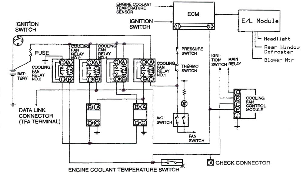
This isn't the only diagram I'm working on...I have the big diagram too..its just too big to post here.
I was working on grounding the coolant temp switch so I could kick up the fans one notch at will. I grounded the wire between pin B on the left most (T-Switch) relay and the switch. The fans stay the same speed. I disconnect the relay and check a few things (relay works like a champ)...finally measuring the resistance between pins C & D an the engine side of the relay connector.
It shows continuity.
WTF? I thought it should be an open circuit until the relay completes the circuit and provides another ground to the fan motors which speeds them up one setting.
So I check a spare (working) fan motor for resistance between D & C on the fan motor connector and yep...continuity there too. They're not seperate windings?
What am I missing here? I thought I had a grasp of how the circuit worked...
Senior Member
Joined: Jun 2003
Posts: 318
Likes: 38
From: Tempe, AZ
Hi trevor there is an easier way to get the dual ground as your making it too complex.
1. (ugly way imop) disconect number three relay connector, using 2 spades make a jumper from pin C to pin D on number 3 relay bypassing the relay creating a permanent second ground.
2. (the stealth way) dissasemble number 3 relay, by separating the body from the shell. looking at the contacts inside there is a small gap, using a spade connector with the plastic sheild removed wedge the spade between the contacts and the body, it will be a very tight fit, causing the contacts to be closed just like the relay would when energized. reassemble. causing the relay to be on constant.
hope this helps.
Eric


First off, check out my review of HKS's Fan Controller, I have quite a bit on how the fan system works -
http://www.clubrx.org/default.asp?id...ntent=41&mnu=3
Which, BTW, that sucker works GREAT. It's kept my water temps at 80-90 deg. C all Florida summer long, with ice cold AC blowing driving daily.
IMHO, it's best to have some sort of programmable control system for the stock fans. This is the KEY to keeping an FD running cool.
Dale
I recently spent some time deciphering and testing the fan control circuit shown in the FSM. Here is the thread:
https://www.rx7club.com/3rd-generation-specific-1993-2002-16/2-trigger-cooling-fans-462760/
If you want to make the fans operate at one speed higher than normal, connect the Blue/Green wire of Relay #3 to ground. For a more permanent solution, you could remove relay #3 entirely and simply connect pin C of the fans to ground.
Good luck,
-s-

Thread
Thread Starter
Forum
Replies
Last Post
atticus_jay
Interior / Exterior / Audio
6
Oct 23, 2015 11:16 AM