
2 trigger cooling fans?

Thread Starter
Registered Abuser
Joined: Jul 2003
Posts: 697
Likes: 0
From: Upper Marlboro
2 trigger cooling fans?
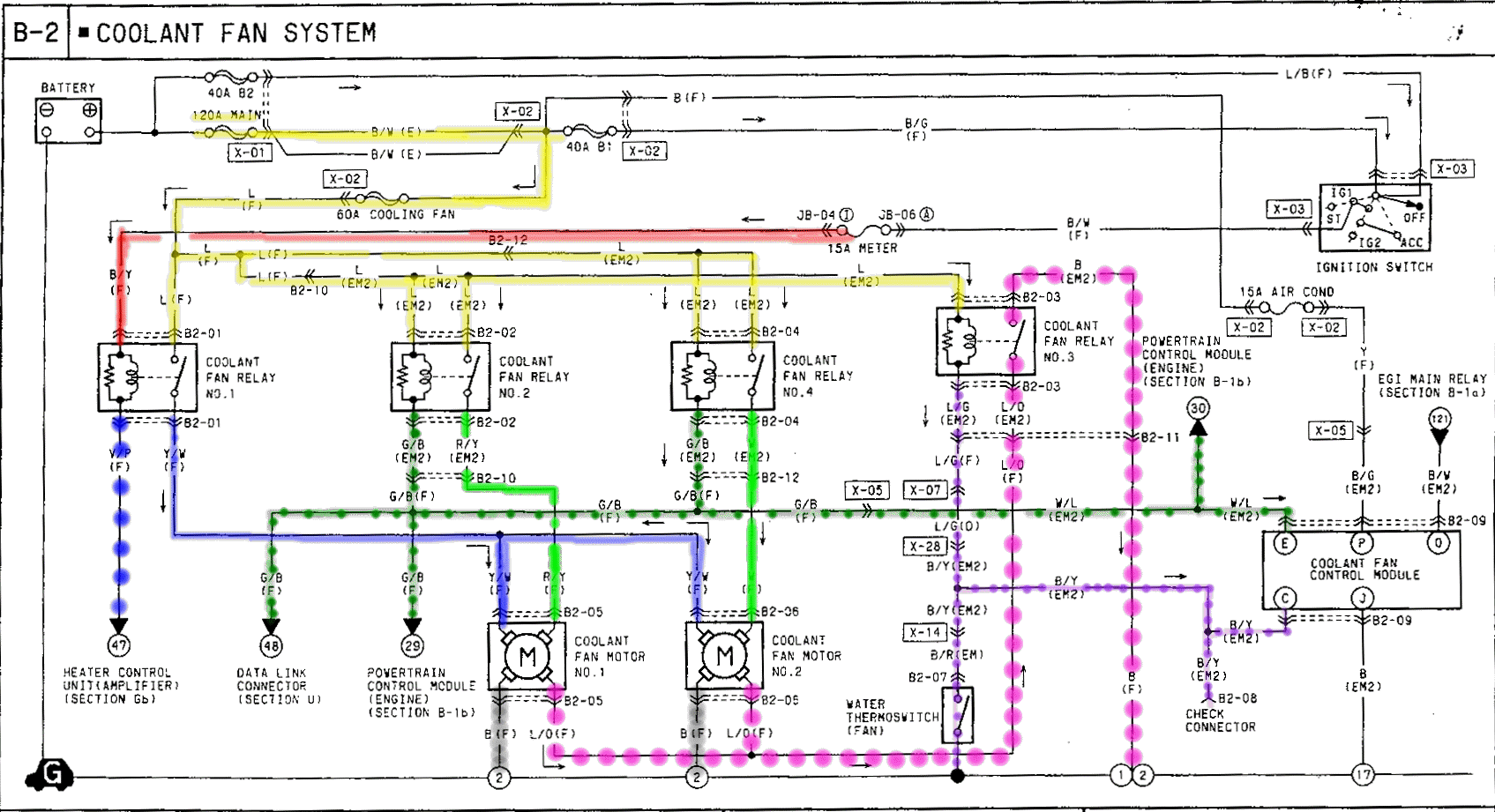
The dark blue line is to the check connector which is behind the ECU on 3rd gens with the cooling fan TSB performed. When I ground this connector the fans dont come on. My thermoswitch also does not trigger the fans. After looking over the diagram I see that the wire route I've traced in blue is the path of both the check connector and the thermoswitch.
I've been able to verify that grounding the check connector does activate cooling fan relay #3 but even when checking with a multimeter that route has no voltage. Where is this route supposed to be getting power from? I'm not understanding how this is ever supposed to work.
The diagram has me thinking that either relay #1 or relays #2 and #4 must be active along with relay #3 for relay#3 to have any kind of effect on the fans. This would make sense to me seeing how we have a 3 speed stock fan. However... Shouldn't the thermoswitch be able to trigger the fans on its own?
Somebody explain this to me because this just doesn't make sense.


Here is a diagram that should be more intuitive. The solid lines should be +12V and the broken lines should be 0V (ground).
Relay No.1 is only controlled by the 'Heater Control Unit,' which is the A/C and fan control switch on the dash.
Relays No.2 and No.4 are peforming the exact same function (this is redundant and dumb IMHO). Think of them as one relay. Connecting the dashed green line to ground will turn the relays on, which will give power to both fans. There are a few different things that can enable these relays, including the Data Link Connector, two seperate ECU pins (which is also redundant and dumb IMHO), and the Coolant Fan Control Module on post-recall cars.
Relay No.3 appears to be switching a second ground to both fans. I'm assuming this will change the speed from low>> medium or from med>> high.
I'm planning to test all this tomorrow, as I can't quite visualize how the switched ground from Relay No.3 is changing the fan speed.
-s-
Thread Starter
Registered Abuser
Joined: Jul 2003
Posts: 697
Likes: 0
From: Upper Marlboro
Thats all fine and good, however, the whole purpose of the thermoswitch is to turn the fans on when coolant temp rise to a given temerature. This is not occuring in my car and this diagram isn't showing where the thermoswitch circuit would even be getting a voltage from. That doesn't make sense to me. Why should the fans comming on DEPEND on another variable. The thermoswitch alone should be enough to trigger the fans.
First, you need to understand what voltage is. It is the measure of the difference between two points. Due to this difference, electricity flows through the wire. For instance, if you put both ends of a wire on your positive battery terminal, nothing would happen, because both ends of the wire are at 12V. If you put one end at the positive terminal (12V) , and the other at the negative terminal (0V, or ground), then electricity will flow through the wire.
In our diagram, when the thermoswitch heats up it will connect the other end of the wire to 0V (ground), which causes electricity to flow through the fan motor.
It would seem that the thermoswitch is not the *only* thing is being used to turn the cooling fans on at a certain temperature. The ECU seems to have more control of things. This makes sense, because the Apex'i PFC gives users the ability to change the fans' turn-on temperature. To test this for yourself, connect the blue/green wire from Relay No.3 to ground, and see what happens. From the diagram, it looks like nothing will happen unless the fans are already on. I'm going to test this tomorrow myself. The Mazda service manual has been wrong about a few electrical things before. Ask anyone who has installed the AEM aftermarket ECU; a couple of wires need to be cut and spliced, because the Mazda FSM shows the wrong info for the Throttle Position Sensor and the AEM engineers didn't double-check.
I agree with you, partially. In my opinion, the fan speed should depend only on the coolant temperature (both before and after the radiator) and vehicle speed. The fan should be controlled using pulsewidth modulation in order to reduce power consumption and eliminate unnecessary wiring, but that's beyond the scope of this particular discussion.
You asked what the diagram meant, and I explained it. Tomorrow I'll check if the diagram is accurate, and find out exactly how the four wires going into each fan motor are connected. Thanks for prompting me to research the function of our cooling fans, it's something I was interested to learn but had put off for a while.
-s-
In our diagram, when the thermoswitch heats up it will connect the other end of the wire to 0V (ground), which causes electricity to flow through the fan motor.
It would seem that the thermoswitch is not the *only* thing is being used to turn the cooling fans on at a certain temperature. The ECU seems to have more control of things. This makes sense, because the Apex'i PFC gives users the ability to change the fans' turn-on temperature. To test this for yourself, connect the blue/green wire from Relay No.3 to ground, and see what happens. From the diagram, it looks like nothing will happen unless the fans are already on. I'm going to test this tomorrow myself. The Mazda service manual has been wrong about a few electrical things before. Ask anyone who has installed the AEM aftermarket ECU; a couple of wires need to be cut and spliced, because the Mazda FSM shows the wrong info for the Throttle Position Sensor and the AEM engineers didn't double-check.
Originally Posted by 13Beast REW
Thats all fine and good, however, the whole purpose of the thermoswitch is to turn the fans on when coolant temp rise to a given temerature. This is not occuring in my car and this diagram isn't showing where the thermoswitch circuit would even be getting a voltage from. That doesn't make sense to me. Why should the fans comming on DEPEND on another variable. The thermoswitch alone should be enough to trigger the fans.
You asked what the diagram meant, and I explained it. Tomorrow I'll check if the diagram is accurate, and find out exactly how the four wires going into each fan motor are connected. Thanks for prompting me to research the function of our cooling fans, it's something I was interested to learn but had put off for a while.
-s-
Last edited by scotty305; Sep 14, 2005 at 04:31 AM.
Thread Starter
Registered Abuser
Joined: Jul 2003
Posts: 697
Likes: 0
From: Upper Marlboro
Thanks for the reply and the research done on your part. At any rate, I understand what voltage and such is. Hopefully I'm not comming across like a *** or anything like one; that is not my intention.
In terms of the precise point of my question... both of our diagrams are showing the exact same thing. The main question is in regrad to what you have shown in a pink dotted line and I have shown in a transparent dark blue line, simply that the path from negative to positive along that particular circuit of wire, is inconclusive as shown by the mazda wiring diagram.
I've tested this circuit under several different conditions and have never been able to measure voltage. I'm nearing the point now where I'm willing to disassemble one of the motors from a spare set of fans that I have.
The line that you've shown in dark blue (and I showed in dotted pink) is going to be ground when the solenoid is on. When you measure it, you should be seeing 0V. I doubt you'll ever see 12V on this wire.
I checked my fans and relays today, and here's what I found:
Relay No.1 is only powered when the ignition is turned on. Relays No. 2, 3, and 4 are always powered, even when the car is turned off. Relays No. 2 & 4 are tied together, they will always do the same thing. Here's a table showing how they work:
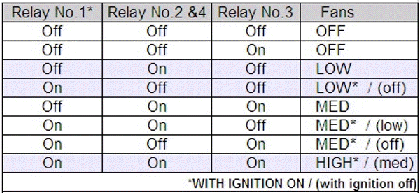
To turn a relay on, ground the signal wire (bottom-left on each relay in the diagram). For instance, to turn on Relay No.1, connect the thin Violet/Pink wire to ground. I used a piece of stereo wire, connected to the negative battery terminal. You'll hear a click when the relay turns off or on. Relays No.2 & No.4 are activated with a thin Green/Black wire, and relay No.3 turns on with the thin Blue/Green wire.
-s-
I checked my fans and relays today, and here's what I found:
Relay No.1 is only powered when the ignition is turned on. Relays No. 2, 3, and 4 are always powered, even when the car is turned off. Relays No. 2 & 4 are tied together, they will always do the same thing. Here's a table showing how they work:
To turn a relay on, ground the signal wire (bottom-left on each relay in the diagram). For instance, to turn on Relay No.1, connect the thin Violet/Pink wire to ground. I used a piece of stereo wire, connected to the negative battery terminal. You'll hear a click when the relay turns off or on. Relays No.2 & No.4 are activated with a thin Green/Black wire, and relay No.3 turns on with the thin Blue/Green wire.
-s-
Last edited by scotty305; Sep 14, 2005 at 02:44 PM.

Junior Member
Joined: May 2004
Posts: 40
Likes: 0
From: Malaysia
Wow... Great thread. Glad i stumbled on this. Now, how do most of you guys go about simplifying the fan's relay system? Considering that relay 2 & 4 are redundant, is it possible to eliminate one of them? Or is it even possible to eliminate most of the relays, if not all of them, and re-route fan control to a "switch" instead, whereby a flick of the switch will switch on and off the fans. Am i making sense here? TIA. 
Last edited by 13Joe; Feb 23, 2006 at 08:04 PM.
Trending Topics


Thread
Thread Starter
Forum
Replies
Last Post
rotor_veux
2nd Generation Specific (1986-1992)
7
Sep 19, 2015 07:13 PM
windom
Adaptronic Engine Mgmt - AUS
4
Sep 11, 2015 04:48 AM