When you click on links to various merchants on this site and make a purchase, this can result in this site earning a commission. Affiliate programs and affiliations include, but are not limited to, the eBay Partner Network.
I had the chance to examine a Body CPU for the FD. The purpose of this thread is to document the components found on CPU #2. Similar to my other threads, this one is broken down by component (i.e. resistors, capacitors, transistors, etc…) and where applicable, part numbers for each component. Some items have notes because of special circumstances.
Some symptoms of a failing Body CPU may include problems with the security & alarm function, headlights, seat belt warning, etc… Please search the forum for more specific troubleshooting procedures on the Body CPU or its affected circuitry. Moreover, consult the BEM (Body Electrical Troubleshooting Manual) for Body CPU test procedures.
This circuit board is becoming more susceptible to capacitor leakage just like the Speedometer circuit board. Evidence of cold solder joints is visible when viewed under a magnification lens. I strongly encourage ALL FD owners to inspect their Body CPU for signs of capacitor leakage and cold solder joints before it causes damage to surrounding components/leads.
Photos of the board will follow shortly. Based upon my observation of this specimen, leaked electrolyte began to corrode the legs of a few transistors. I anticipate some of these legs to fall off when attempting to replace solder. Please note that these transistors are no longer made and therefore must be sourced from second-hand markets. The same holds true for the MPU.
A special thanks to EpyonFD for the opportunity to examine and attempt a repair on this Body CPU board (CPU #2). Without further ado, the list of components are below.
Note 1 – Values and part numbers extrapolated from capacitor codes stamped on component.
Note 2 – Component must be “mini” sized otherwise the circuit board will not fit into case.
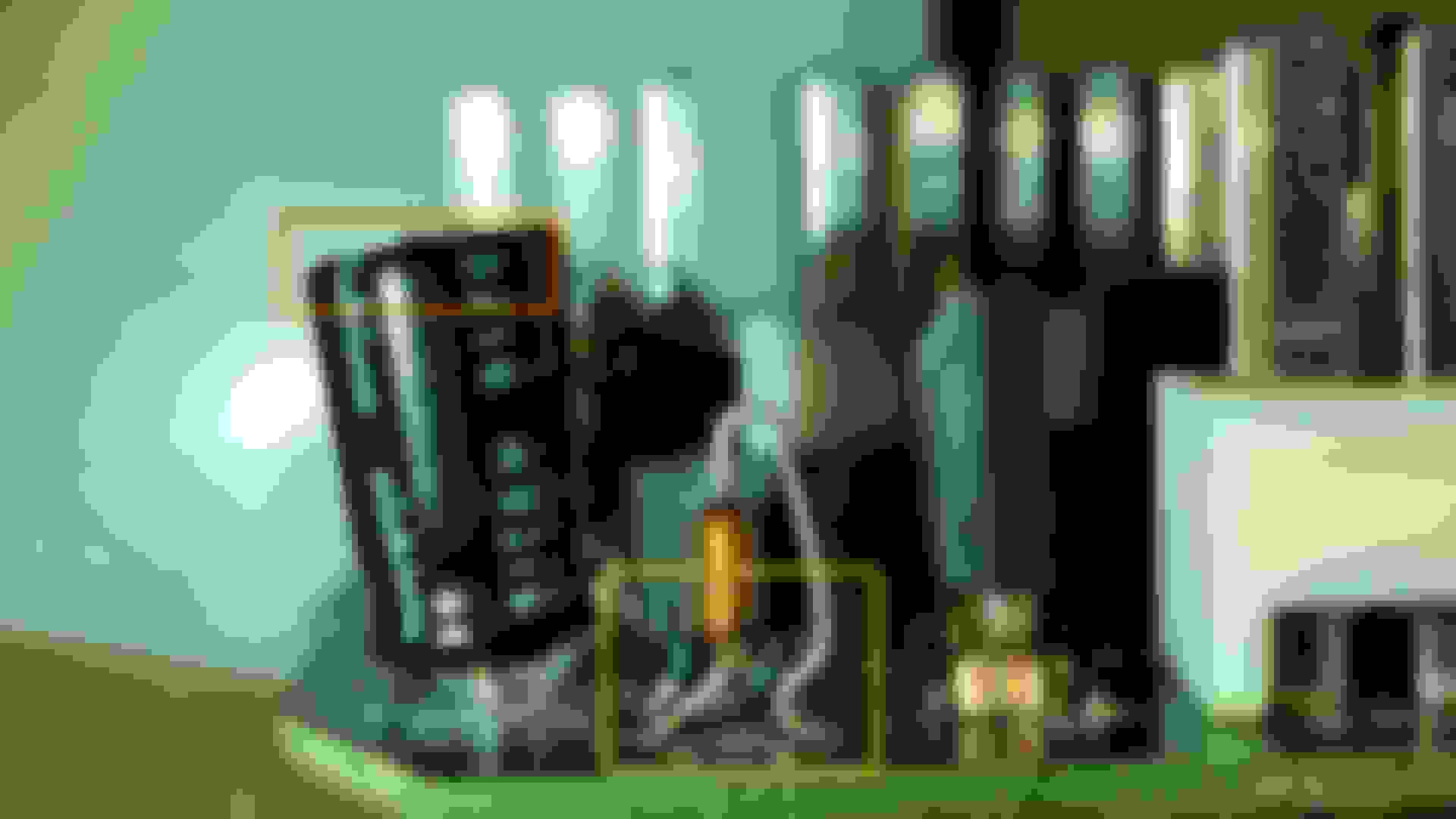
Here are some photos that reflect damage caused by leaked electrolyte from a few capacitors. Read the captions for more information.
Cheers,
George
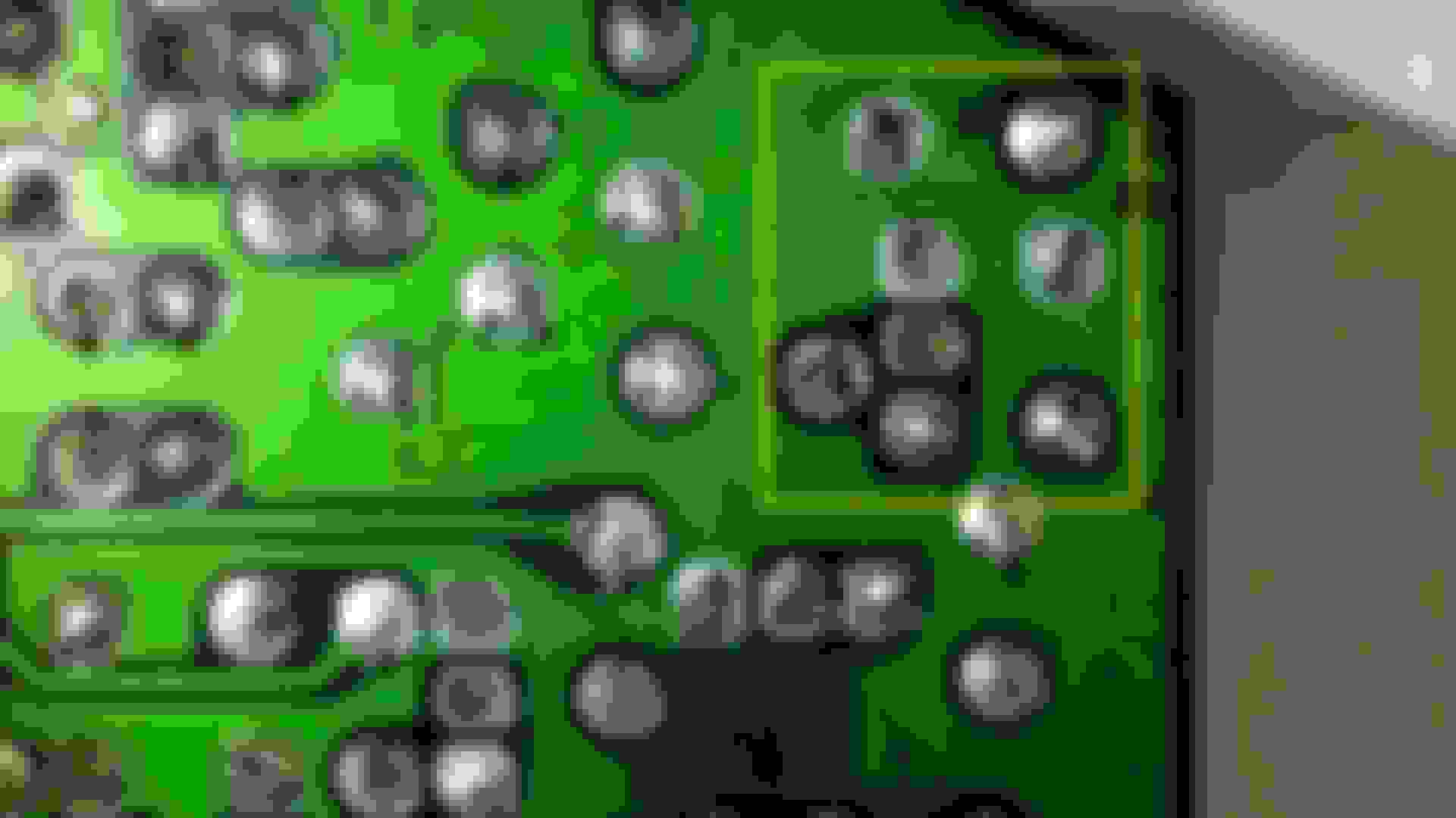
Yellow boxes show the corrosive properties of electrolyte on a circuit board. Solder in these joints will need to be replaced.
Different angle showing damage in yellow boxes.
Solder should have a shiny look to it. These have heavy stains of brown and green corrosion.
The orange box shows a slight bulge to the top of this capacitor. It may be hard to see with a shadow effect. The yellow box shows the damage to this transistor and diode. I suspect the leads to the transistor to fall out when replacing the solder.
Another angle showing the damage to transistor legs.
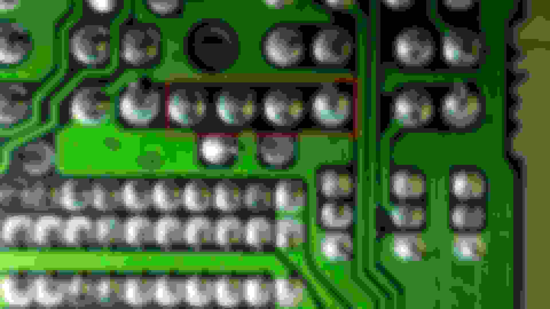
The yellow box shows the tarnished look of solder joints on the back side of the board. These are potentially cold solder joints.
A closer inspection reveals these are cold solder joints and require replacement. Note the frosted appearance. I used a sharpie to mark several bad spots.
The red box shows an example of good solder joints. See how shiny they look?
I imagine the failure mode for most of these will be failing caps?
Thanks George!
Dale
Dale,
Thank you and glad to lend a hand! To answer your question, YES! Failing capacitors will lead the CPU #2 failure. Although, it would not be the single culprit. A few years ago, I encountered a security alarm failure. The board did not look damaged so I suspected the logic within the MPU failed. After the Body CPU was replaced, the problem was fixed. However, I believe we will begin to see more body-related gremlins pop up as our cars continue to age.
One important note about replacing 3 capacitors. They are C5, C6, and C7, and are located at the bottom (thin) side of the board. These components MUST be small in size otherwise the circuit board will not fit into the housing. These capacitors are known as miniature capacitors, aka mini caps. The part number recommendations listed in Post #1 offer the best replacement option.
The photo below shows the size needed. Note, these are the original components.
Cheers,
George
The blue boxes show the smaller size of these capacitors. Do not use larger ones otherwise the board cannot be installed into its housing.
^Forum member Andre the Giant successfully replaced his leaking capacitors as far back as 2011. Said it was easier than repairing the speedometer/odometer if that helps persuade any DIYers. For me, I was thankful the CPU2 was/is still available to purchase brand new @ approx. $250 (ha). For the 'non-start/click-click-start' issue prevalent for many FD owners at one time or another, a new CPU2 is generally the ultimate fix.
Note: Many electrical gremlins originate from a failing CPU2, not simply the 'click-click-start' issue.
Thanks for sharing the link on CPU #2 repairs and sharing one of your experiences. I agree that the Body CPU is a critical failure point. The photos above show a worst case scenario - when the FD sits for too long these gremlins quickly sneak up and strike when least expected. I agree with Andre's assessment that replacing a cap is a straight forward process. However, when electrolytes are not properly neutralized then it causes more damage and hence more work.
For the 'non-start/click-click-start' issue prevalent for many FD owners at one time or another, a new CPU2 is generally the ultimate fix.
Note: Many electrical gremlins originate from a failing CPU2, not simply the 'click-click-start' issue.
I fought the click-click-start problem for YEARS. I bypassed the security relay and still had it - at that point the CPU is out of the loop.
The only true fix for me was a starter booster relay. After I installed that I have NEVER had a problem. That was after rebuilding the whole starting/charging harness, replacing the ignition switch, the clutch switch, and the security relay with new parts.
To clarify, when jumping the H302 security relay allows the car to start wout issue again (poor man's fix/yet very genius!), a faulty CPU2 is the likely culprit. I chose to bite the bullet and buy a new one since I was starting to also experience gremlins w the security system such as periodic honking when unlocking the doors. Had even tried replacing the H302 relay at the time but to no permanent avail. Ironically, I deduced the solution to my problems after perusing a few of your informative posts on the same subject. And just like you, I haven't looked back since replacing the CPU (except for that time when I snipped the wrong resistor in order to eliminate the hyper flashing when converting to LED turn signals - face palm!).
Thank you for the compliments. Welcome back to the forum after your sabbatical! Once the replacement transistors arrive I will then provide some post-repair photos for reference purposes.
I would also like to add the following recommendation when cleaning up electrolytes that leaked onto a circuit board. This was my advice (slightly modified) to EpyonFD from his thread here: Post #15
Spot clean affected areas with distilled water and baking soda. Use a tooth brush, cotton swab, and/or acid brush to clean the localized areas with baking soda and water solution. This would be the same as cleaning your car battery so expect to see some foaming action. That is the baking soda reacting to the acid. Do NOT soak the board or let the water stand. Let it drain off the board. Dry the affected areas with a hair dryer. Slowly move it (hair dryer) around to avoid hot/burn spots. Once dried, use isopropyl alcohol to clean up the solder joints. Inspect each joint for any damage. The component may not need to be replaced but the solder may need replacement. This will ensure a positive physical bond and a clean electrical bond.
The circuit board photos in this thread and from the link are the exact same board. Your results may vary dependent upon the amount of time acid was left to run down the circuit board and eat up components. This is a similar occurrence when the odometer blanks out in the speedometer board. Note that the Body CPU and Speedometer are mounted in a vertical plane. Therefore, gravity helps the electrolyte run down the length of the circuit board. That is the reason why so many components are impacted by this leak.
Redoing my FD01/CPU#2 board. Does anyone know if C6 is polarity dependent? It does not have a polarity symbol on the circuit board. The new capacitor also has no polarity symbol but does charge on one plate as a typical cap. Can I place it either way?
Thanks
Mike
Raymond,
I never checked availability. My board had two caps leaking pretty bad. I finished replacing the caps last night late and hope it works. If not, I will be looking for a new one and will let everybody know if still available new.
Mike
The CPU#2 may no longer be available as a stand alone board. However, there may still be Body CPU units (the hole thing with flasher CPU) available for sale. It has been a while since I last bought a Body CPU so my info is several years old. Ray Crowe would be the man to comment on this part availability. One thing for certain, they are not cheap!
I am experiencing issues with my car where it doesn't want to start at all. I'm not sure if this is tied to the CPU, may be failing. I replaced my starter, bypassed the security relay and clutch switch. I also checked my ignition switch and replaced it with a working unit. The car still doesn't want to turn over. I'm not sure if the CPU is causing the car to not recognize that I am trying to start it. I also notice my windows won't go up or down. I checked all my fuses and did notice one was blown the B2 Fuse. All the other ones were fine.
NEED HELP!
As stated in Post #1, the purpose of this thread is to document the components found on CPU #2. Refer to the Body Electrical Troubleshooting Manual (BEM) and Wiring Diagram Manual (WDM) for the functions of the Body CPU (CPU#2). Additionally, the power windows sound like an different problem - they do not flow thru the Body CPU. Again, refer to the WDM, Section K-1 for the Power Window wiring diagram.
If you are concerned that CPU#2 is the failed part then you can remove and inspect it for suspect internal components.
Also stated in Post 1, "Some symptoms of a failing Body CPU may include problems with the security & alarm function, headlights, seat belt warning, etc… Please search the forum for more specific troubleshooting procedures on the Body CPU or its affected circuitry. Moreover, consult the BEM... for Body CPU test procedures."
*CORRECTION*: CPU#2 Pin 1U is labeled Power Window relay but it is not drawn on either J-4 diagram or K-1 diagram. Additionally, the Power Window Relay is not discussed in the troubleshooting procedures found in the BEM.
My apologies for any confusion!
Last edited by Gen2n3; Jul 5, 2019 at 11:38 AM.
Reason: Added Correction
Aren't these the same caps? It looks like the manufacturer's part numbers are identical. The only difference that I could tell is the warehouse from which to order them from. Nonetheless, it is good to list a second resource for parts in case one warehouse is out of stock.
Do you have other Digi-key equivalent part numbers to list? I'll update the list when more components are identified.
Yes, I believe it is identical.
If I am not mistaken, it it the only electrolytic in the list above that is a "Mouser" VS a "Digikey" part number to consolidate a single order rather than pay twice for shipping in two independent store fronts, unless I missed a detail.