When you click on links to various merchants on this site and make a purchase, this can result in this site earning a commission. Affiliate programs and affiliations include, but are not limited to, the eBay Partner Network.
My '94 touring model has a failed temperature actuator (FD01-61-A60). This isn't available basically anywhere, so I'm hoping someone knows how to repair/rebuild it (or some other random thing that can take it's place).
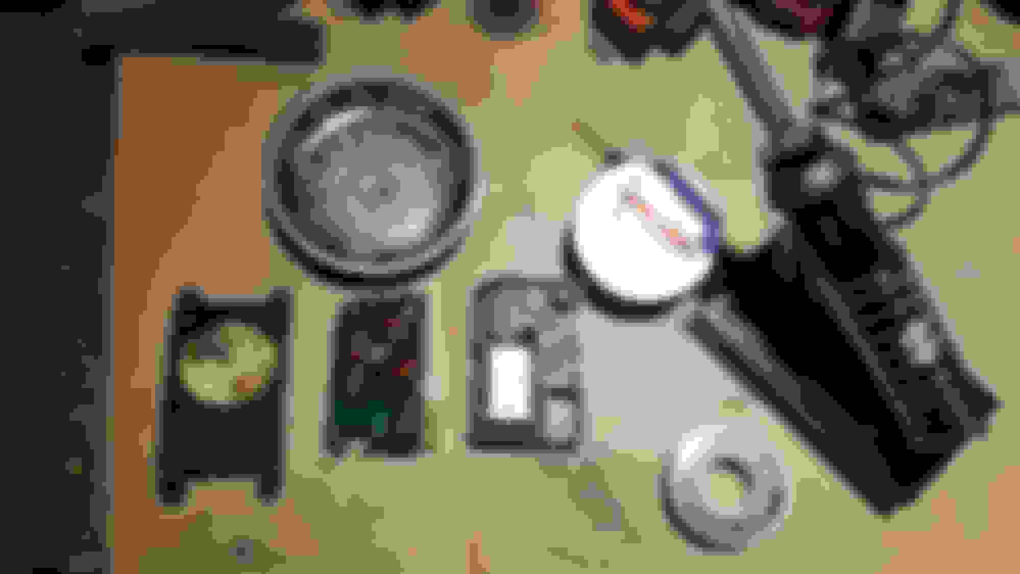
The actuator is easy to disassemble, doesn't contain any odd springs or anything.
Electronics are trivial, 1 plug, one cap (power smoothing), two diodes, two sweeper arms, and a potentiometer (resistance dye used by one of the sweepers).
Mechanically there is the motor, a worm gear, and a few step down gears
The cap was dead on my board, and the plug had some odd solder corrosion. I replaced the cap and reflowed the connector (easy with a soldering iron) and the actuator is now working.
Just figured I'd post this in case anyone else hits a similar issue.
The actuator didn't move at all (and was stuck on full heat)
I followed the FSM procedure (although the FSM says to remove the dash, that isn't required, just some creative screwdriver work).
When I applied 12V to the contacts (in either polarity), nothing happened... I ripped it apart and checked all the gears and the motor directly, then started trying to figure out why the circuit board was faulty.
And it turned out to be bad solders in the climate control system (I hear the second gen guys know a little bit about that...)
Wanted to add some info to this thread as I just went through the same fix for my blend door actuator. My car would not switch from cold air to warm in the winter. Problem turned out to be cold solder joints in the actuator, which is NLA from Mazda.
Really cool little part with some similarities to the pop up headlight motors. Easy to fix
30min job if you heat up your iron while removing the actuator. The only pita part is the actuator cover, which has one screw that you need to get creative with.
I fluxed and remelted every joint on the board. Same routine for other cold solder joints. Hot 30 amp iron so you don't have to heat the joint forever and damage components. I put Flux on my joints before remelting to help draw any impurities to the surface.
Anyone know what part numbers work to replace the capacitor (power smoothing) and two diodes? I think my cap has gone out but it doesn't say any part numbers or indicators on it.
Post some closeup pictures of the capacitor and the diodes, they usually have meaningful info printed on them. And if you have a set of calipers, measure the pin spacing and the length/width/height of the capacitor too.
Post some closeup pictures of the capacitor and the diodes, they usually have meaningful info printed on them. And if you have a set of calipers, measure the pin spacing and the length/width/height of the capacitor too.
Here's some pics, Looks like the black diodes? say E 1E or E 13/31, and the Blue Cap says 103. It's hard to get a caliper in between the connectors but it looks like the pins are 5mm apart almost the same as the width and maybe 3mm tall 2mm wide.
The diodes look like just through-hole rectifier diodes. These will probably work, they might be larger than the originals but you can measure if you've got calipers. The diode body being a little larger shouldn't be a problem, but you might need to match the size of the legs/leads/wires so they fit in the mounting holes: https://www.digikey.com/en/products/...SB2060/5992790
The capacitor marking 103 probably means it is 10000 pF capacitance (10 * 10^3). We can hope the original was a ceramic capacitor because those tend to look like that shape and ceramics are pretty robust which would be good for automotive use. And we can assume it needs to be rated to survive at least 50V, and reasonable temperatures. Here's a possible substitute, it's a similar color and shape as the original but probably better temperature performance than the original. https://www.digikey.com/en/products/...3KNU06/5863671
I haven't soldered that exact board, but the materials look more fragile than we would see in most modern circuit boards. If you're not very experienced at soldering, I would try to find someone who is because you don't want to damage the board or the copper traces when trying to remove the original parts. At the very least, I would want a temperature-controlled soldering iron and nice fine/small diameter solder with a low melting point. This solder is not cheap and it's a large enough spool to rework probably 1000 of those circuit boards, but I like that it has a little silver in it for strength and the lead keeps the melting temperature low. https://www.digikey.com/en/products/...20-1OZ/9558147
I would cut the diodes and capacitors near where they mount to the board, so they don't act as heat sinks, then add solder to heat up the original joint and then tap the board so the little metal legs fall out of the mounting holes when the solder is liquid. Try not to overheat the board and also don't pull hard on anything, you don't want to pull the traces off the board. After installing the new diodes and capacitor and maybe reflowing the original solder joints on the original connectors, scrub with a toothbrush and alcohol then wipe with a clean cloth rag to remove the flux after everything has cooled. Some flux can be corrosive and you don't want it to sit on the board eating things away for the next decade. The alcohol absorbs the flux and the rag removes the alcohol + flux mixture.
Thanks scotty305, i took my board and this info to a local electronics repair store and they got it working like new. Turns out it was just a bad capacitor.