
Aftermarket Gauge Wiring Techniques?

Aftermarket Gauge Wiring Techniques?
Hey guys,
Through the years of owning my FC I installed at least 5 different gauges. This started when I was in high school and knew little to nothing about what I was getting myself into. Then later on I realized I had made a great mess of things underneath my dash...I want to avoid this with my FD and was wondering if there are any clean, simple install advice you guys had to run the power and lights for aftermarket gauges on an FD? Also any good access points through the firewall? I've searched for some write-ups but haven't found anything that fully pertains to this topic. ie, I know how to do it, just want to know how to do it and make it look professional .
.
Thanks,
~Anthony
Through the years of owning my FC I installed at least 5 different gauges. This started when I was in high school and knew little to nothing about what I was getting myself into. Then later on I realized I had made a great mess of things underneath my dash...I want to avoid this with my FD and was wondering if there are any clean, simple install advice you guys had to run the power and lights for aftermarket gauges on an FD? Also any good access points through the firewall? I've searched for some write-ups but haven't found anything that fully pertains to this topic. ie, I know how to do it, just want to know how to do it and make it look professional
Thanks,
~Anthony


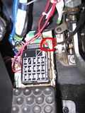
*I think this is linked to in the FAQ's. I like the routing he used for the wires/lines, but IMO there's a cleaner switched power (see below) ----> Boost and Water Temp Gauge Install
*Use soldered connections and shrink tubing whenever possible.
*52mm gauges. The larger ones look out of place IMO.
*For back-light power I used the wire going to the (former) ashtray light in the console.
*Switched 12v power is circled. Just use a decent spade connector....
*Use soldered connections and shrink tubing whenever possible.
*52mm gauges. The larger ones look out of place IMO.
*For back-light power I used the wire going to the (former) ashtray light in the console.
*Switched 12v power is circled. Just use a decent spade connector....

Personally, i wouldn't use that source for the water temp. It's about the same location at the stock gauge temp sensor location which we all know isn't exactly the best spot.
Also, for getting a switched source, you can go to your local auto store and pick up an add a circuit fuse holder. It'll allow you to "add a circuit" without interfering with the circuit it's running on.
But, i don't like tapping to already existing circuits on the car. I picked up my own fuse block to add circuits for my gauges and accessories. I only used the add a circuit for a switched source to activate the relay for the fuse block, low draw.
Friendly stalker
Joined: Dec 2011
Posts: 505
Likes: 2
From: Hamilton On
Where would you put it then? A lot of us don't want to tap into the waterpump.
I have mine set up as per the write up and I find it almost dead even with my PFC so I wouldn't worry too much about it being that far off.
I have mine set up as per the write up and I find it almost dead even with my PFC so I wouldn't worry too much about it being that far off.
I added an accessories fuse block when I relocated the battery, and use the source Sgtblue posted as trigger.
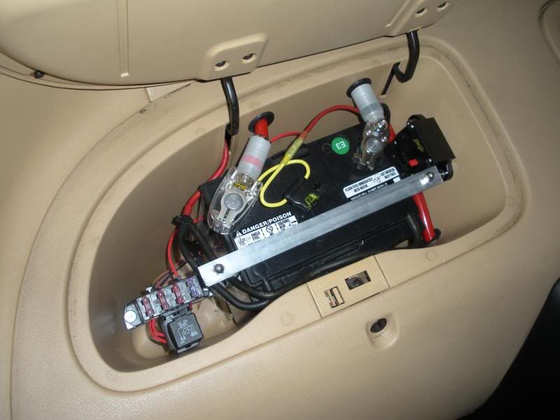
With that I have 3 12V switched sources, I used them for my wideband, gauges and EBC.
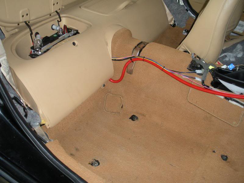
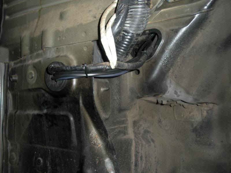
As far as routing lines to the engine bay, I use the passenger side fender access.
With that I have 3 12V switched sources, I used them for my wideband, gauges and EBC.
As far as routing lines to the engine bay, I use the passenger side fender access.
https://www.rx7club.com/build-thread...044952/page10/
The water filler neck is also where the fan thermoswitch and the sensor where the ECU get it's temps so that seemed like a prime place to put my plx water temp sensor.
Trending Topics
As for temp gauge sensor install, if you're still stock-ish and have the throttle-body coolant line in place, I recommend putting the sensor in the line. Easy, accurate, reversible and no drilling and taping necessary. See post #36 for list of what you need.
---> https://www.rx7club.com/3rd-generati...d-idea-392910/
Picture from some years ago of my sensor installed per that thread:


Junior Member
Joined: Oct 2013
Posts: 35
Likes: 0
From: toronto
*I think this is linked to in the FAQ's. I like the routing he used for the wires/lines, but IMO there's a cleaner switched power (see below) ----> Boost and Water Temp Gauge Install
*Use soldered connections and shrink tubing whenever possible.
*52mm gauges. The larger ones look out of place IMO.
*For back-light power I used the wire going to the (former) ashtray light in the console.
*Switched 12v power is circled. Just use a decent spade connector....
*Use soldered connections and shrink tubing whenever possible.
*52mm gauges. The larger ones look out of place IMO.
*For back-light power I used the wire going to the (former) ashtray light in the console.
*Switched 12v power is circled. Just use a decent spade connector....


I do recommend a fuse regardless of where you source 12v.

Awesome, this almost seems too easy.
I picked up an inline fuse block per your recommendations. Is there a "rule of thumb" or general standard that determines what size fuse to run? I'll be running 3 gauges in line to the 12v ign source.
I picked up an inline fuse block per your recommendations. Is there a "rule of thumb" or general standard that determines what size fuse to run? I'll be running 3 gauges in line to the 12v ign source.

Thread
Thread Starter
Forum
Replies
Last Post
streetlegal?
New Member RX-7 Technical
13
Mar 17, 2022 02:46 PM