
#1 Rotary Problem Fix

Thread Starter
"Elusive, not deceptive!�
Joined: May 2007
Posts: 930
Likes: 13
From: Slidell, LA
#1 Rotary Problem Fix
The Rotary�s biggest flaw is the hump at the spark plug opening in the housings.
This problem area can be minimized by using cold plugs and a good water pump. But this is the Root Cause of Apex Seal problems.
Hard seals chip; softer seals warp, bow, or bend.
The actual problem was aggravated by a Mazda improvement. Mazda found the combustion burn-rate could be improved by widening the distance between the leading and trailing plugs. In order to do this as economically as possible they kept the through-bolt locations in the same place so they could use the existing side plates.
This in turn decreases the size of probably the most important water passage in the engine!
This Generational housing change is shown it the following image.
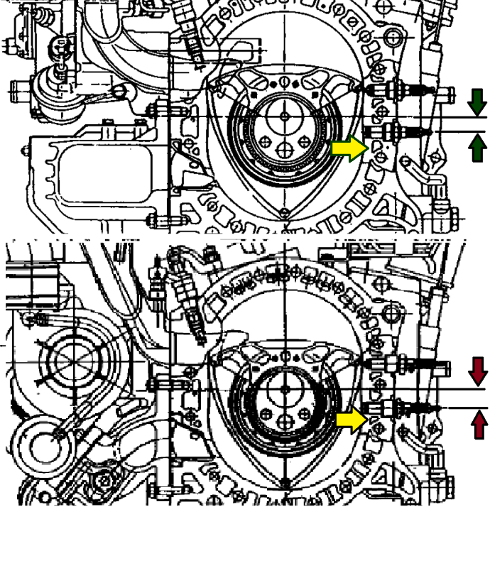
Notice that the water passages in the top housing drawing gradually get larger which corresponds to the heat map of the housing.
The lower drawing is of the latest version with smaller water passages on the more critical higher temp section.
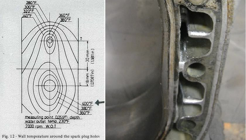
This is what the actual flow looks like on a 3rd housing.
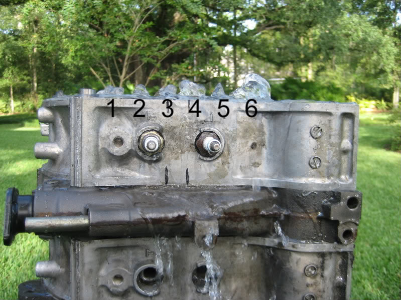
We need to increase flow at passages #3 and #5.
This next shot shows the solution. The housing is ported to increase the flow at this critical area.

This is a critical area so as always a compromise must be had� cutting enough to increase flow while not weakening the housing surface which supports over a 1000 psi (although over a very short period of time).
Do not cut the area next the plug boss anymore than removing the casting slag. Concentrate on cutting the thru-bolt side and the floor next to the housing face. I join the 3rd gen�s end mill cuts from one side to the other. They are about 5mm deep. Try not to cut through boss for the thru-bolt but if you do it is not a big problem. I use a 6" long 1/4" burr.
I have presented most of this information before in different threads but I thought it would be best to consolidate it as Problem/Solution , especially for new guys and home engine builders.
Barry
This problem area can be minimized by using cold plugs and a good water pump. But this is the Root Cause of Apex Seal problems.
Hard seals chip; softer seals warp, bow, or bend.
The actual problem was aggravated by a Mazda improvement. Mazda found the combustion burn-rate could be improved by widening the distance between the leading and trailing plugs. In order to do this as economically as possible they kept the through-bolt locations in the same place so they could use the existing side plates.
This in turn decreases the size of probably the most important water passage in the engine!
This Generational housing change is shown it the following image.
Notice that the water passages in the top housing drawing gradually get larger which corresponds to the heat map of the housing.
The lower drawing is of the latest version with smaller water passages on the more critical higher temp section.
This is what the actual flow looks like on a 3rd housing.
We need to increase flow at passages #3 and #5.
This next shot shows the solution. The housing is ported to increase the flow at this critical area.
This is a critical area so as always a compromise must be had� cutting enough to increase flow while not weakening the housing surface which supports over a 1000 psi (although over a very short period of time).
Do not cut the area next the plug boss anymore than removing the casting slag. Concentrate on cutting the thru-bolt side and the floor next to the housing face. I join the 3rd gen�s end mill cuts from one side to the other. They are about 5mm deep. Try not to cut through boss for the thru-bolt but if you do it is not a big problem. I use a 6" long 1/4" burr.
I have presented most of this information before in different threads but I thought it would be best to consolidate it as Problem/Solution , especially for new guys and home engine builders.
Barry
Nice info. Ever seen a twin dizzy engine? Mazda already moved the spark plug and tension bolt slightly lower for 74. They also moved another tension bolt lower under the exhaust port.


As long as the porting is done correctly, it seems like it would help. Too bad it would cost so much money to do the kind of testing we would need to validate the change--basically rigging up a specially instrumented engine.
Do you have a theory of how this would relate to discussion about squish flows and knock occurring in the trailing portion of the combustion chamber? Are you addressing spontaneous catastrophic failures, slower wearing of the apex seal, or both?
Do you have a theory of how this would relate to discussion about squish flows and knock occurring in the trailing portion of the combustion chamber? Are you addressing spontaneous catastrophic failures, slower wearing of the apex seal, or both?
Hi Barry,
Instead of just opening up for better flow, would increase in surface area by making grooves be better?? Also, what is your thoughts on E85 vs. say premium pump gas on this matter? Maybe my thought process might be wrong but would E85 lower the temp the area might face?
Now at it, I would like to pick your brain to see what your thoughts on Evan 0 pressure coolant vs. say 50/50 mix or lower coolant mixture. My thought is that ultimately its about heat exchange and Evan's 0 pressure indicates that its the nucleated boiling could be reduced by their product... But Water has much better thermal conductivity and with pressure and speed of flow, not sure this nucleated boiling is something to really worry about. I almost think purified water, small percentage of glycol could be more beneficial.
Your thoughts on the fluid is appreciated.
I think Mazda is working at almost the same problem here ...
http://wardsauto.com/vehicles-amp-te...otary-new-life
"Specifically, centrifugal force pushes the seal onto the housing surface. In low engine-rpm ranges, or under low-load conditions, gas pressure in the combustion chamber can cause the seal to lift off the surface, resulting in combustion gas leaking into the next chamber.
By changing the shape of the troichoid housing, the seals remain flush to the housing, Hitomi says. �In addition to reducing emissions, better sealing improves fuel economy and overall performance.�
A second engineering enhancement focuses on ignition.
�I can�t specify how we plan to address this problem,� the Mazda engineer says, �but the rotary�s spark plug is in a recessed position (below the housing surface), compared to that of a piston engine.
�This causes ignitability problems and increases fuel consumption. We�ve found a way to make dramatic improvements,� he says."
Trending Topics
Joined: Oct 2001
Posts: 6,279
Likes: 728
From: Florence, Alabama
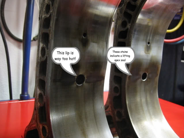
warning: these pictures are graphic. women and children please leave the room...

Barry has put his finger on one of the, uh, challenges for the rotary. i see the carbon wings on every motor i disassemble. your motor has them.
just so we are clear, wherever you see carbon on the housing face the apex seal is NOT contacting the housing. this has many ramifications:
loss of compression
neighboring chamber pollution
apex seal bouncing/chattermarks
eventual apex seal warpage
flatted apex seal shoulder
bad, bad, bad.


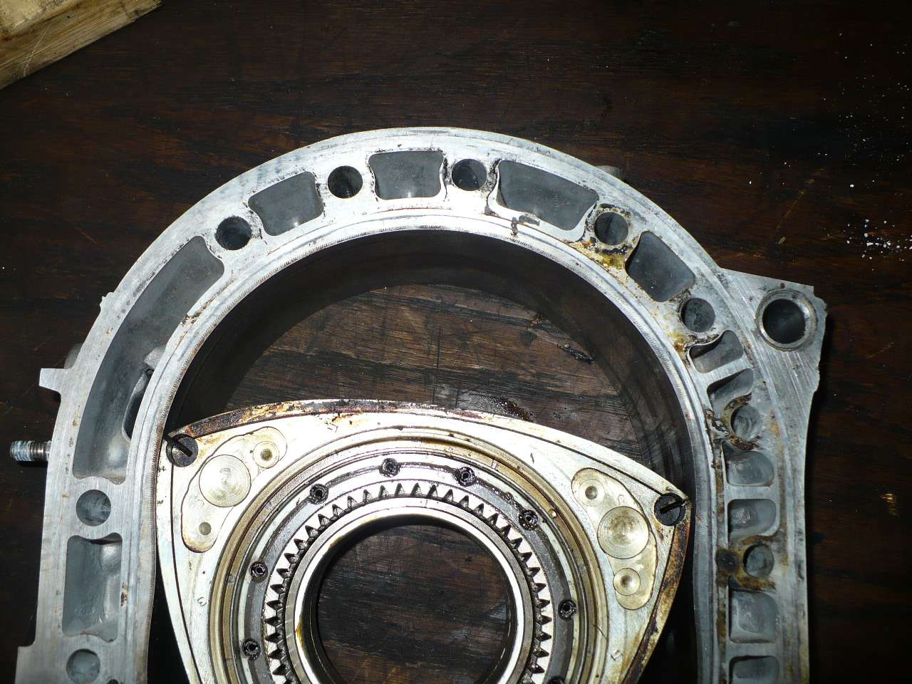
here is part of my solution... i chamfer the plugholes thus taking a bit of the top off the protuberance. it works. i see less carbon deposit on the housing. here is what they look like. while the housings don't have alot of miles on them they did make 514 hp.
i do not see dark carbon on my housings w this mod. (the darker carbon deposit on the high side of the plug hole was caused when the diffuser went thru the motor and broke the end of the apex seal)
removing heat from around the plug certainly is part of the answer and it does appear some aluminum could be removed. running cooler plugs is a positive step as is cooling things w AI.

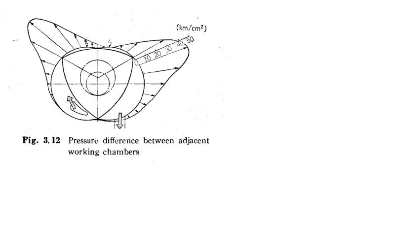
so what happens as the apex seals pass over the plugs? in the following picture the apex seal is exactly passing the lead plughole. note that the trailing chamber is at maximum volume and contains air and fuel and is at approximately your boost pressure.... say 20 psi.
the lead chamber is at near max combustion chamber pressure. the exhaust port is not open. this pressure is so great it drives your car forward.
the apex seal is lifted off the rotor housing by the growth of the leading plug boss. because of the great(est) disparity between neighboring chambers mazda chose to shroud the plug so it would decrease apex seal lift.
any gas travel at this point is from the leading to the trailing chamber due to the pressure differential.
picture 2 captures the apex seal being lifted by the leading plug. we see the trailing chamber compressed to maybe half it's max volume... so the pressure is around 40 psi at 20 psi boost.
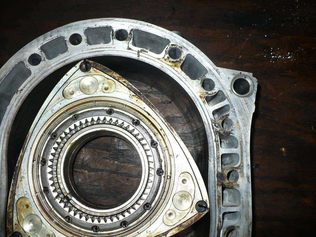
note that the exhaust port is fully open at the point where the apex seal centers on the lead plug and is being lifted from the housing. there is significantly less pressure differential between the two neighboring chambers but there still is a very significant difference. again, flow should go from lead to trail.

i will be taking a close look at the metal around my plugs going forward...
thanks Barry
howard
Barry has put his finger on one of the, uh, challenges for the rotary. i see the carbon wings on every motor i disassemble. your motor has them.
just so we are clear, wherever you see carbon on the housing face the apex seal is NOT contacting the housing. this has many ramifications:
loss of compression
neighboring chamber pollution
apex seal bouncing/chattermarks
eventual apex seal warpage
flatted apex seal shoulder
bad, bad, bad.
here is part of my solution... i chamfer the plugholes thus taking a bit of the top off the protuberance. it works. i see less carbon deposit on the housing. here is what they look like. while the housings don't have alot of miles on them they did make 514 hp.
i do not see dark carbon on my housings w this mod. (the darker carbon deposit on the high side of the plug hole was caused when the diffuser went thru the motor and broke the end of the apex seal)
removing heat from around the plug certainly is part of the answer and it does appear some aluminum could be removed. running cooler plugs is a positive step as is cooling things w AI.
so what happens as the apex seals pass over the plugs? in the following picture the apex seal is exactly passing the lead plughole. note that the trailing chamber is at maximum volume and contains air and fuel and is at approximately your boost pressure.... say 20 psi.
the lead chamber is at near max combustion chamber pressure. the exhaust port is not open. this pressure is so great it drives your car forward.
the apex seal is lifted off the rotor housing by the growth of the leading plug boss. because of the great(est) disparity between neighboring chambers mazda chose to shroud the plug so it would decrease apex seal lift.
any gas travel at this point is from the leading to the trailing chamber due to the pressure differential.
picture 2 captures the apex seal being lifted by the leading plug. we see the trailing chamber compressed to maybe half it's max volume... so the pressure is around 40 psi at 20 psi boost.
note that the exhaust port is fully open at the point where the apex seal centers on the lead plug and is being lifted from the housing. there is significantly less pressure differential between the two neighboring chambers but there still is a very significant difference. again, flow should go from lead to trail.
i will be taking a close look at the metal around my plugs going forward...
thanks Barry
howard
Great info as usual Barry, thanks for sharing. It seems that increasing flow in this area would be helpful whether using standard water/glycol coolant or Evans NPG. Have you had the opportunity to repeat the water-flow visualization test after modifying the housings? It seems it would be useful to have greater flow rates in the hotter areas than on the intake side of the housings, but then again there are some constraints you have to work around.
I really enjoyed reading about your in-chamber pressure measurements, what have you been up to lately? I realize there are plenty of people out there doing interesting things and not necessarily talking about it on the internet.
I really enjoyed reading about your in-chamber pressure measurements, what have you been up to lately? I realize there are plenty of people out there doing interesting things and not necessarily talking about it on the internet.
Joined: Jan 2002
Posts: 922
Likes: 0
From: KC, KS
Since I've had my FD I've been looking at re-builder site's for when that day does come. I've seen on a few of them that they offer coolant passage modification. Are these modifications the same between builders or are some taking different approaches?
Thread Starter
"Elusive, not deceptive!�
Joined: May 2007
Posts: 930
Likes: 13
From: Slidell, LA
As long as the porting is done correctly, it seems like it would help. Too bad it would cost so much money to do the kind of testing we would need to validate the change--basically rigging up a specially instrumented engine.
Do you have a theory of how this would relate to discussion about squish flows and knock occurring in the trailing portion of the combustion chamber? Are you addressing spontaneous catastrophic failures, slower wearing of the apex seal, or both?
Do you have a theory of how this would relate to discussion about squish flows and knock occurring in the trailing portion of the combustion chamber? Are you addressing spontaneous catastrophic failures, slower wearing of the apex seal, or both?
Very good questions Raymond.
I was mostly addressing the problem the apex seal chip/wear/warp.
The only reason we don’t see catastrophic failures from this raised area is that the pressures are almost equal across the leading plug opening.
The trailing is more critical because of the pressure delta.
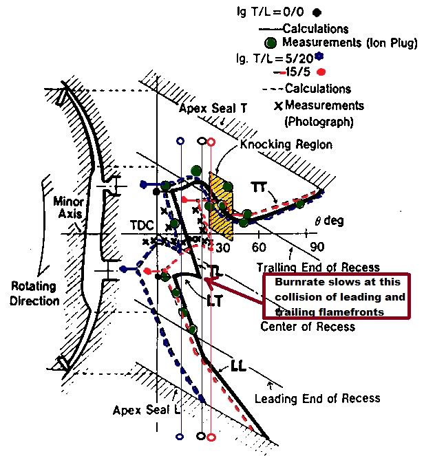
The sharp cracks that develop on both holes however could be a source for preignition but that is just speculation.
For others what Raymond is alluding to on the knock area can best be seen in this Mazda chart.
Thread Starter
"Elusive, not deceptive!�
Joined: May 2007
Posts: 930
Likes: 13
From: Slidell, LA
Howard, thanks for the input. I usually use a rubberized polishing wheel to smooth a rounded chamfer on that sharp edge.
This from Yamamoto�s research depicts what you are describing.
This from Yamamoto�s research depicts what you are describing.
Thread Starter
"Elusive, not deceptive!�
Joined: May 2007
Posts: 930
Likes: 13
From: Slidell, LA
Great info as usual Barry, thanks for sharing. It seems that increasing flow in this area would be helpful whether using standard water/glycol coolant or Evans NPG. Have you had the opportunity to repeat the water-flow visualization test after modifying the housings? It seems it would be useful to have greater flow rates in the hotter areas than on the intake side of the housings, but then again there are some constraints you have to work around.
I really enjoyed reading about your in-chamber pressure measurements, what have you been up to lately? I realize there are plenty of people out there doing interesting things and not necessarily talking about it on the internet.
I really enjoyed reading about your in-chamber pressure measurements, what have you been up to lately? I realize there are plenty of people out there doing interesting things and not necessarily talking about it on the internet.
No pictures to compare to the original flow tests. I will put that on the to-do list.
As for our guidance on what might work let us go to the Masters�. and the R26B.
Check out their water passages around the plugs�. Look familiar?
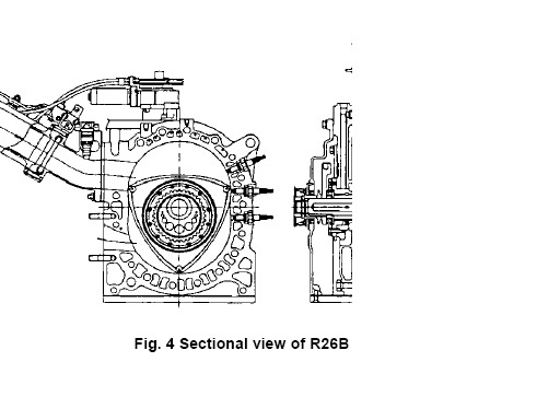
On the In-Chamber testing; I just got the TFX system back from Canada with a new Hall Effects Transducer for timing so testing is resuming.
Just hit 1137 psi for the first time. Boost on a 10lb spring creaping to 12psi Darned TO4Z feels good even at that low (for some guys) pressure!
Barry
Thread Starter
"Elusive, not deceptive!�
Joined: May 2007
Posts: 930
Likes: 13
From: Slidell, LA
Hi Barry,
Hi Phil, can't wait till DGRR, Jack and Jonathan are getting anxious.
Instead of just opening up for better flow, would increase in surface area by making grooves be better?? Also, what is your thoughts on E85 vs. say premium pump gas on this matter? Maybe my thought process might be wrong but would E85 lower the temp the area might face?
I don�t think anything changes from the water side with E85. Its lower temps help in getting more volume into the chamber after that we need as much heat as 93 oct for power. A faster burn-rate would help.
Now at it, I would like to pick your brain to see what your thoughts on Evan 0 pressure coolant vs. say 50/50 mix or lower coolant mixture. My thought is that ultimately its about heat exchange and Evan's 0 pressure indicates that its the nucleated boiling could be reduced by their product... But Water has much better thermal conductivity and with pressure and speed of flow, not sure this nucleated boiling is something to really worry about. I almost think purified water, small percentage of glycol could be more beneficial.
Phil you nailed it in my mind. The Evans with higher boiling point than 50/50) versus water removing temps faster.
Most people don't realize that the water pump pressurizes the system to over 40 psi till it cavitates at about 7400 rpm. (Oops another thread)
I use around 20/80 water in warm weather.
Your thoughts on the fluid is appreciated.
Joined: May 2005
Posts: 2,745
Likes: 0
From: North Bay, Ontario
Well, I'm not sure I am "qualified" to contribute anything to this thread, but Barry mentioned it to me and I'd like to throw a couple ideas up, and introduce some other questions.
Firstly, something to think about which although is obvious, is very unique about the rotary engine and relevant to this discussion. The only cooling to the combustion area comes from the water-cooling system. Let's repeat that. The only cooling to the combustion area comes from the water-cooling system. This obviously differs slightly from 4-stroke piston engines, where the combustion area is both A) Used half as often for combustion vs. the rotary engine for the same RPM and B) partially cooled by the incoming air charge (hence why "they" can get away with filling blocks with solid aluminum and relying on pure methanol as fuel to cool the heads on a drag engine). In this aspect, it is in my opinion (read: don't flame) that AI, water injection, E85, and even pure methanol as fuel do not really contribute to cooling the combustion chamber surface of the rotary engine to any significant degree. At the end of the day, we are still dealing with constant combustion and a leading plug area that is near 400* F as illustrated by Barry, regardless of our best efforts. Now, I do believe that all the things I just mentioned have their place in a rotary engine, and do help reduce pre-ignition, air charge, and a host of other benefits, don't get me wrong.
So, on the same point as above, if water-cooling is the only effective method to remove heat from the combustion area, then the 400*F recorded in the surface of the combustion chamber leading plug must have to be transferred in a majority part to the aluminum water jackets directly on the opposite side, no? Can anyone tell me what type of pressure water requires to prevent boiling at anywhere near 400*F? It's not very good. So, my question of the day is how much boiling really does occur at the site of the leading plug boss and area directly surrounding it, and would eliminating boiling (using something like Evans) at the sacrifice of thermal conductivity lower the surface temperature or not?
Personally, I like afgmoto's method of introducing extra fluid into these critical areas: https://www.rx7club.com/rotary-car-performance-77/latest-experiment%85failure-751977/page2/, and I will be doing similar using 2 electric water pumps to try introducing as much fluid flow as possible, one into the stock waterpump location and the second feeding the spark plug bosses directly.
Secondly, I feel that providing small amounts of fluid "relief" (back to the rad or inlet side of waterpump) after the critical combustion side of the rotary will help free up restriction and create more flow across the combustion area, and less around the less critical areas (similar to Mazda keeping water jacket diameters very small around the less critical areas of the engine). At the end of the day, flow, heat transfer and contact area, as Barry has worked on maximizing, are the only universally positive modifications to this dilemma, and without very expensive monitoring equipment, it's still a best-guess as to whether or not we are making progress.
Taylor
Senior Member
Joined: Nov 2008
Posts: 357
Likes: 0
From: Czech republic
Can anyone tell me what type of pressure water requires to prevent boiling at anywhere near 400*F? It's not very good. So, my question of the day is how much boiling really does occur at the site of the leading plug boss and area directly surrounding it, and would eliminating boiling (using something like Evans) at the sacrifice of thermal conductivity lower the surface temperature or not?
Good cooling system must be able to keep coolant temperatures low and circulate fast, otherwise coolant would pick up too much heat and raise its teperature, what would hinder subsequent heat transfer.
To the point of water injection, water, or water vapor can absorb heat even at very high temperatures, much higher than its boiling point. So it is wrong to believe that water won't act as internal coolant.
Joined: Oct 2001
Posts: 6,279
Likes: 728
From: Florence, Alabama
"water, or water vapor can absorb heat even at very high temperatures, much higher than its boiling point. So it is wrong to believe that water won't act as internal coolant."
agree.
i could get into a long post about BTUs and all that stuff but let's just be empirical, real, for a moment.
AI reduces heat within the rotary internals. fill up your FD w 93 octane, turn off your AI, run 20 PSI.... call me, i will rebuild your motor.
perhaps you are referring to the boundry layer since you specifically use the word "surfaces." certainly the reduced BTUs effect the surfaces less, but overall the heat is partially offset w AI.
speaking of surfaces and boundry layers... AI cleans the carbon off one of the biggest heat soaking offenders, the rotor surface. the rotors absorb huge amounts of heat, so much so that mazda fills them w oil to transfer the BTUs. how much heat do you think they absorb if they have a tenth of an inch of carbon on them?
i will say, w re to heat transfer that i have never been in love w the RacingBeat mod. sure it adds surface area to radiate heat into the coolant but the ripple topography impedes flow and perhaps causes pressure differences that could create gas... which doesn't transfer heat well.
i do run the trick water pump impeller for whatever it is worth.
another consideration is with the aftermarket water pump idler pulley... i'll bet that 75% of them can be turned by hand and slip at higher RPMs.
i suggest that they get snugged before the entire rotary cooling system gets redesigned.
hc
Last edited by Howard Coleman; Mar 5, 2012 at 06:59 PM.

But, I have talked to some.
A few years ago I had a conversation with someone at Mazmart re Evans.
Sorry, don't recall all the details, should have written them down.
But, I do remember the conclusion of the conversation.
The guys at Mazmart will use Evans in their own street engines.
They do not use it in their own race engines.
That was good enough for me.


Barry
I would not expect the carbon tracing to be the result of localized heat, at least not entirely. It appears the lifting of the apex seals at the trochroid humps would be more due to the mechanical dynamics of the rotor to housing interfaces. Mr. Hitomi describes it best:
"Even with our current 1.3L Renesisrotary, gaps can develop between the apex seal and troichoid housing in light-load operation when imbalances in centrifugal force and gas pressure occur,� he says.
Specifically, centrifugal force pushes the seal onto the housing surface. In low engine-rpm ranges, or under low-load conditions, gas pressure in the combustion chamber can cause the seal to lift off the surface, resulting in combustion gas leaking into the next chamber".
With respect to heat transfer, surface area in contact with the coolant is the key to efficient heat removal. Heat transfer (I know Howard Coleman didn't want to go here but..) is time based whereas, for example, heat energy if transfered from the metal structure to the coolant molecules which are in contact with the structure then from the coolant molecule to the next molecule and so forth through the coolant cross section. This takes time and with the coolant moving full flux transfer is incomplete or better stated inefficient. Now, if there was enough metallic surface area to contact every passing coolant molecule a near perfect transfer of energy to thermal equilibrium would occur in very short time. Temperature differential between the source of the heat and the coolant enables a greater amount of heat to be transfered until equilibrim between the two. It's really that simple for fluids. The issue becomes as heat transfer from the engine structure to the coolant, expansion of the coolant occurs which is simply increasing the spacing between the molecules and consequently resisting further heat transfer between molecules. When a steam pocket reveals in the coolant system heat transfer is greatly inhibited and the situation becomes a self eating watermelon. Any coolant flow over a steam vapor area will quench to a point however.
Don't forget also that much of the chamber heat is removed from the oil spray within the rotor....
Tom
Joined: May 2005
Posts: 2,745
Likes: 0
From: North Bay, Ontario
"water, or water vapor can absorb heat even at very high temperatures, much higher than its boiling point. So it is wrong to believe that water won't act as internal coolant."
agree.
i could get into a long post about BTUs and all that stuff but let's just be empirical, real, for a moment.
AI reduces heat within the rotary internals. fill up your FD w 93 octane, turn off your AI, run 20 PSI.... call me, i will rebuild your motor.
agree.
i could get into a long post about BTUs and all that stuff but let's just be empirical, real, for a moment.
AI reduces heat within the rotary internals. fill up your FD w 93 octane, turn off your AI, run 20 PSI.... call me, i will rebuild your motor.
But, how much does water and/or meth injection affect EGT's, which are IMO the closest measurement to combustion temperatures us average enthusiasts can log? And how much influence would this change (if any) in combustion temperatures have on the housing temperature in question? The most prominent example that comes to my mind is Rx72c's 700 whp pump/water injection car, which is running copious amounts of pure water (~1600CC's of it), and still sees ~950*C EGT's. Is the water really "cooling" the combustion chamber? Maybe yes, but the EGT's don't seem to show it. Is it preventing the motor from self-destructing? Without a doubt! I am a firm advocate of AI myself. I would have cooked engines many a time if it weren't for AI.
That being said, if Mazda is measuring 400*F average on the rotor housing surface directly around the leading plug -0.059" from the surface- at an EGT between 1700 and 1800*F, and a heavily water-injected, high-horsepower engine is still seeing 1700-1800*F EGT's, I'm going to go out on a limb and say that the housing temperature is still at least 400*F with a fairly heavy water-fuel ratio, which was my only point about AI. Maybe someone can show me the light if I'm missing it.
speaking of surfaces and boundry layers... AI cleans the carbon off one of the biggest heat soaking offenders, the rotor surface. the rotors absorb huge amounts of heat, so much so that mazda fills them w oil to transfer the BTUs. how much heat do you think they absorb if they have a tenth of an inch of carbon on them?
Now, to back Barry's theory about this up, I will add that there is a reason professionals such as Carlos Lopez have "secret cooling mods" that they only offer to their serious customers, and that they have the reputation to justify it.
Senior Member
Joined: Nov 2008
Posts: 357
Likes: 0
From: Czech republic
Barry
I would not expect the carbon tracing to be the result of localized heat, at least not entirely. It appears the lifting of the apex seals at the trochroid humps would be more due to the mechanical dynamics of the rotor to housing interfaces. Mr. Hitomi describes it best
I would not expect the carbon tracing to be the result of localized heat, at least not entirely. It appears the lifting of the apex seals at the trochroid humps would be more due to the mechanical dynamics of the rotor to housing interfaces. Mr. Hitomi describes it best
He described it in somewhat marketing language, but otherwise its correct. Most people won't believe that forces around TDC are actually centripetal and gas pressure under apex seal must be high enough to keep seal tracking housing surface. So groove clearance and different expansion properties of many apex seal materials and designs comes to mind... There is also phenomena that causes apex seal to lift from surface - detonation...
I hope that you can see my point. EGT's can be viewed only as reference number to your particular combination or as absolute number when you consider life of your turbine.
And how much influence would this change (if any) in combustion temperatures have on the housing temperature in question? The most prominent example that comes to my mind is Rx72c's 700 whp pump/water injection car, which is running copious amounts of pure water (~1600CC's of it), and still sees ~950*C EGT's. Is the water really "cooling" the combustion chamber? Maybe yes, but the EGT's don't seem to show it.
That being said, if Mazda is measuring 400*F average on the rotor housing surface directly around the leading plug -0.059" from the surface- at an EGT between 1700 and 1800*F, and a heavily water-injected, high-horsepower engine is still seeing 1700-1800*F EGT's, I'm going to go out on a limb and say that the housing temperature is still at least 400*F with a fairly heavy water-fuel ratio, which was my only point about AI. Maybe someone can show me the light if I'm missing it.
Thread Starter
"Elusive, not deceptive!�
Joined: May 2007
Posts: 930
Likes: 13
From: Slidell, LA
Barry
I would not expect the carbon tracing to be the result of localized heat, at least not entirely. It appears the lifting of the apex seals at the trochroid humps would be more due to the mechanical dynamics of the rotor to housing interfaces. Mr. Hitomi describes it best:
"With respect to heat transfer, surface area in contact with the coolant is the key to efficient heat removal. Heat transfer (I know Howard Coleman didn't want to go here but..) is time based whereas, for example, heat energy if transfered from the metal structure to the coolant molecules which are in contact with the structure then from the coolant molecule to the next molecule and so forth through the coolant cross section. This takes time and with the coolant moving full flux transfer is incomplete or better stated inefficient. Now, if there was enough metallic surface area to contact every passing coolant molecule a near perfect transfer of energy to thermal equilibrium would occur in very short time. Temperature differential between the source of the heat and the coolant enables a greater amount of heat to be transfered until equilibrim between the two. It's really that simple for fluids. The issue becomes as heat transfer from the engine structure to the coolant, expansion of the coolant occurs which is simply increasing the spacing between the molecules and consequently resisting further heat transfer between molecules. When a steam pocket reveals in the coolant system heat transfer is greatly inhibited and the situation becomes a self eating watermelon. Any coolant flow over a steam vapor area will quench to a point however.
Don't forget also that much of the chamber heat is removed from the oil spray within the rotor....
Tom
Man this is great... so many great thinkers have chimed in.... Makes me want to build a tent for some strange reason.
Tom on this image of Howard's notice the light carbon stains just past the waist of the trochoid with chatter marks.... that might be caused by the centripetal lifting you and Liborek are referring to.
The dark carbon pockets are from the spark plug boss bulging into the chamber.
Side note: The carbon @12:00 above the plug boss is probably from using softer apex seals that have worn the face of the seal... causing slightly less leakage at the hump but more everyplace else.

On this next housing it probably uses harder seals maybe stock and the apex triangle side is probably on the viewed right side. The seal is rocking more heavily on the left side because of having 2 vs 1 spring contacting points on the apex seal. This is what causes the chipped/broken end of the apex seal that we see to often.

i performed a different fix about a year ago by increasing the surface area in those passages versus opening them up.
won't know if it ever made a difference likely at all, since the car also runs AI and never has a spot of carbon to leave witness marks.
but as mentioned, this is just a flaw to the engine and not carbon sticking due to heat. it's due to the seal not having enough tension as it skips over the hump and has to push out to seal quickly, sometimes skipping over the pressurized area of the spark plugs due to boost lifting the seal hence why the trailing hole is so small, minimizing seal lift at a critical combustion rotor position(you will also see those stains to the side of the exhaust ports, as exhaust backpressure lifts the seal and rams it into the rotor and releases just after port closing), you do not see this carbon tracing around the plugs in naturally aspirated engines but you do still mostly see the lack of wear in that area due to weak sealing characteristics. after the humps in the rotating angle of the engine is the weakest point for the seals to bounce back into position and have decent holding force, like running a bike over a jump and trying to get the wheels to hit the ground just after it, the faster the engine runs the less tension can be applied after the ramp.
this is where more apex seal spring tension comes into play, but the sacrifice can be housing wear in all areas except this one. is it worth it? that is the million dollar question. combustion gases potentially mixing with the incoming charge and igniting it is bad news.
this is also the start point for the seals to begin chattering. more spring tension and chatter= fubar housing.
that isn't carbon above the spark plug holes, it is heat discoloration from the center of the apex seal trying to dig into the metal surface. take two bars of steel and rub them together with alot of force and pressure and you will see the same result, i have seen that spot purple and even blue in color before. note the wear channel at the top of the picture and follow it directly down.
in my time cutting housing surfaces the center position and the outer edges are always worn the most, in essence the housings are generally an "m" shape. i attribute this to the heat applied to these areas, the seal ends pick up friction from 2 angles and the center absorbs heat from the peripheral exhaust and then quickly releases it with the oil from the OMP injector which is where the wear line actually originates which spreads wider and wider until it meets the plug holes and continues around the whole housing.
i also believe the leading was moved down as a safety measure, it overlaps the exhast port opening more when you position the rotor over the leading plug hole, the exhaust port is opening alleviating some of that issue of combustion forcing back into the intake charge.
Last edited by RotaryEvolution; Mar 6, 2012 at 12:51 PM.