
#1 Rotary Problem Fix

I figure I post this in case some of you haven't read this article... especially this part,
Full article here: http://wardsauto.com/vehicles-amp-te...otary-new-life
My question is, would change in trochoid design really solve this issue we see on this thread??
Fuel economy and emissions were improved in the developmental engine “first, by changing the shape of the troichoid housing,” the Mazda executive says.
“The rotary has many seals, and ‘sealability,’ particularly at the apex, or tip, of the rotor has been a longstanding problem” dating back to the mid-1960s and the Cosmo Sport, Mazda’s first rotary car.
“Even with our current 1.3L Renesisrotary, gaps can develop between the apex seal and troichoid housing in light-load operation when imbalances in centrifugal force and gas pressure occur,” he says.
Specifically, centrifugal force pushes the seal onto the housing surface. In low engine-rpm ranges, or under low-load conditions, gas pressure in the combustion chamber can cause the seal to lift off the surface, resulting in combustion gas leaking into the next chamber.
By changing the shape of the troichoid housing, the seals remain flush to the housing, Hitomi says. “In addition to reducing emissions, better sealing improves fuel economy and overall performance.”
My question is, would change in trochoid design really solve this issue we see on this thread??
Thread Starter
"Elusive, not deceptive!�
Joined: May 2007
Posts: 930
Likes: 13
From: Slidell, LA
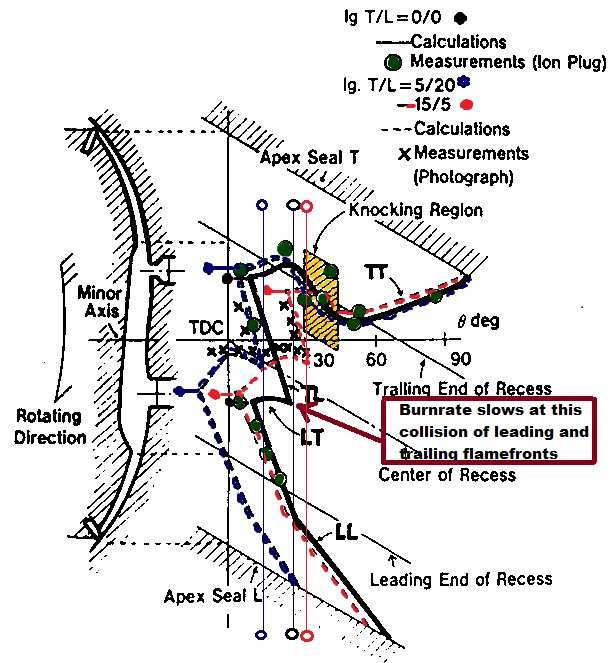
The Rotary face is so long that it requires two plugs to get the charge burned before the exhaust opens.
But the burn rate changes when the two fronts collide.
Read the 16X direct injection patent. They explain the best length/breadth ratios.
The 12A is better than the early13B geometry. The newer 13B increased the plug spacing��hence the small water passages.
The 16X is scaled up 12A , narrow and long. Better burn rate.
The crook in the burn rate curve happens at the collision shown below.
Old [Sch|F]ool


Joined: May 2001
Posts: 12,876
Likes: 575
From: Cleveland, Ohio, USA
This thread is as good a place as any to ask this.
When people do heavy relief of the water jacket fins, why is it done at the inner surface, and not at the outer surface?
It would seem to me that it would make more sense to cut away the inner fin at the outside, so that the inner surface (which is what we want to cool) ends up with more surface area to contact the coolant. Sure, you're reducing the distance that the heat needs to travel, but you're greatly reducing the surface area that the coolant can contact.
Also makes me wonder if this wouldn't actually make the warping problem worse.
Joined: Jan 2002
Posts: 922
Likes: 0
From: KC, KS
I'm curious as to how the temps would be different if there was 1 plug in the housing that was closer between the two currently. Granted this would require a spark strong enough to provide a clean burn. This would only require 1 hot spot to be cooled as opposed to two.
One thing you guys have to remember is that the rotary engine as we know it was basically designed in the mid 1960s. There hasn't been a major redesign of engine geometry since then. It was basically sketched out on paper and calculated with a sliderule or computers the size of our garages with less power than our cellphones. Mazda and Audi never made many fundamental changes to its design, whereas the mass production piston engine has had drastic changes to combustion chambers and basic geometry since then.
The water passageways were not optimized with modern fluid dynamics software. The combustion chamber and proportions were not calculated out with special modeling software. They did not have the same level of equipment and instrumentation during prototypes. So Mazda is only now going back to the proverbial drawing board to make big changes to the rotary. All they had done to the 13B was tweak it for about 30 years, from the early 1970s to the early 2000s.
I can name all sorts of design methods and software tools commonly used in the design of engines today. The basic rotary as we know it did not have the benefit of those tools. The engine design process has changed drastically in the past 15 years.
A plug in the location you describe wouldn't work. If you think of the rotary as a peanut, you are talking about putting the plug near the narrow part of the peanut. The problem is that the combustion properties would not work out. The rotary combustion chamber is divided into leading and trailing portions. You would probably have major quenching of the flame if you put the plug there.
The old single plug rotary engines have tended to run in the trailing position actually. One example is the KKM 502, the first production rotary engine in the NSU Spider.
The water passageways were not optimized with modern fluid dynamics software. The combustion chamber and proportions were not calculated out with special modeling software. They did not have the same level of equipment and instrumentation during prototypes. So Mazda is only now going back to the proverbial drawing board to make big changes to the rotary. All they had done to the 13B was tweak it for about 30 years, from the early 1970s to the early 2000s.
I can name all sorts of design methods and software tools commonly used in the design of engines today. The basic rotary as we know it did not have the benefit of those tools. The engine design process has changed drastically in the past 15 years.
I'm curious as to how the temps would be different if there was 1 plug in the housing that was closer between the two currently. Granted this would require a spark strong enough to provide a clean burn. This would only require 1 hot spot to be cooled as opposed to two.
The old single plug rotary engines have tended to run in the trailing position actually. One example is the KKM 502, the first production rotary engine in the NSU Spider.
Old [Sch|F]ool
Joined: May 2001
Posts: 12,876
Likes: 575
From: Cleveland, Ohio, USA
One thing you guys have to remember is that the rotary engine as we know it was basically designed in the mid 1960s. There hasn't been a major redesign of engine geometry since then. It was basically sketched out on paper and calculated with a sliderule or computers the size of our garages with less power than our cellphones.
Computers help us design things faster, but not necessarily better.
A lot of the changes in tech over the years are due not to computational ability, but cheapness of processes and materials. Remember that in the 30s and 40s, DOHC was considered to be "old tech" and passe' because it required a lot of skilled labor and craftsmanship to produce compared to simple, contemporarily modern valve-in-block designs.
Similarly, we may be able to engineer an engine to finished product status without ever machining one chip of metal, but that isn't to say that the engineers in the day couldn't produce good designs. It just took longer, and they had more considerations to think about. Check out the history of the production of the B29's engines for an interesting study in how they engineered things - make an engine, find the weak points, and improve on it, just like any other engineering. The tools may be out of date in 2012 (who uses, say, brittle lacquer anymore?) but the knowledge was definitely there.
In the end, EVERY manufactured product has cost as an overarching concern. There is always a point where you have to figure that something is "good enough". No, the rotary's coolant passages aren't perfect, but there are enough engines out there that live well beyond their design life to show that Mazda did a decent job of engineering a produceable product that performed satisfactorily in its intended purpose.
If you want a bar-no-costs everything-is-perfect car, you could try to hunt down a Vector W8, which was intended with those kind of standards in mind...
I am talking about specific tools and engineering processes used in design of water jackets that were not available in the early 1970s when the 13B was designed. These tools are undoubtedly being utilized in Mazda's development of whatever new rotary in development, most likely the successor to the 16X prototype. Check out some temperature and fluid visualizations from the latest generation of engines:
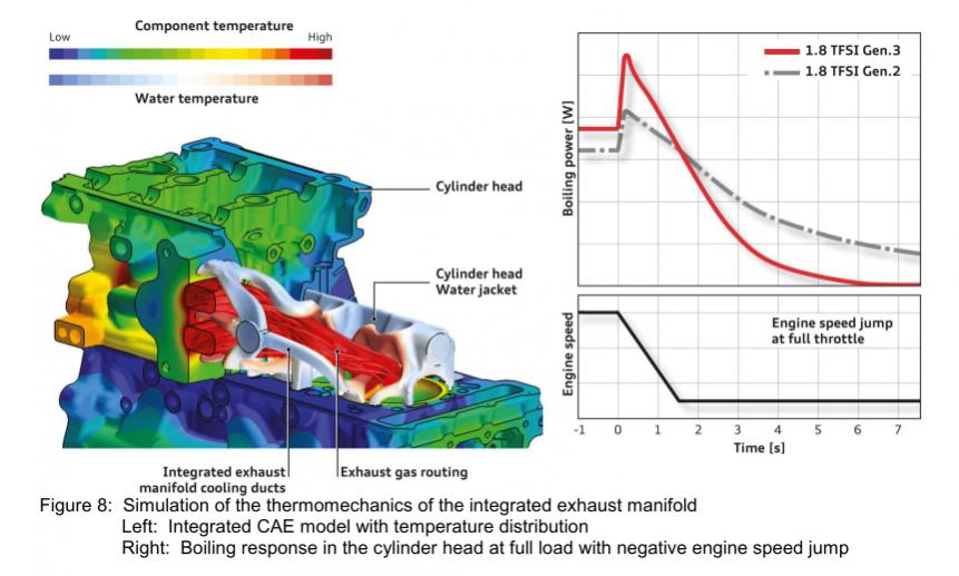
That's from the VW EA888 series 1.8T engine that will be coming out in Europe very soon. The water jackets from the head flow into the integrated exhaust manifold to cool down the exhaust temperature. This combined with port injection + direct injection allows the engine to run at a 14.7:1 air/fuel ratio at almost all rpm & load points under boost & WOT. Next up the is the 1LR-GUE engine used in the Lexus LFA:
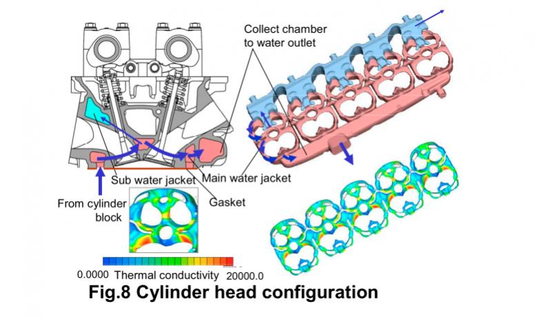
The modeling used in conjunction with fractional factorial design of experiments methods results in much better temperature distribution among the cylinders for improved knock resistance and emissions. Fractional Factorial Design of Experiments is a statistically-based method used in designing very complex aspects of a vehicle, such as water jackets and combustion chambers. It's a way of figuring out how many iterations of a design to try (either in simulation or with physical tests) by finding statistical trends. So with water jacket design, we might have a bunch of factors such as the dimensions of certain water jackets, the flow speed, turbulance, etc. For a combustion chamber we have piston shape, intake port flow coefficient, intake port charge motion (swirl, tumble, squish flows), etc. We use the Design of Experiments methods to direct these kinds of studies--it's basically commercially available planning software based on this methodology.
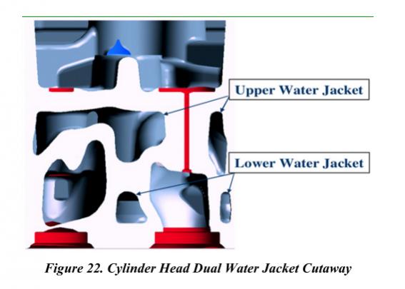
The last thing to check out is a cutaway of the coolant passages in the current Ford 6.8 diesel:
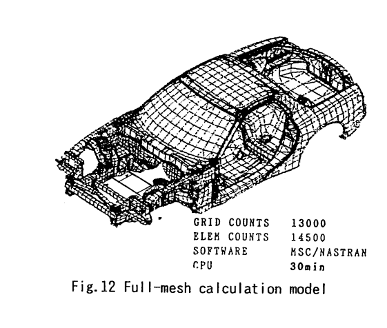
These designs couldn't realistically be optimized like we can now with the latest generation of modeling software. You can't eleventy billion guess-and-check prototypes. That being said, the models still have to be validated and prototypes are still built, but only in the later stages of design. It's a much more sophisticated way of doing things than building one-off designs and measuring temperature and flow at select points. By the way, Mazda used low-resolution finite element models when designing the FD chassis:
I hope that clarifies what I was saying--it's not always just about saving labor costs, although I suppose you could say that everything ultimately comes down to money in some way.
Thread Starter
"Elusive, not deceptive!�
Joined: May 2007
Posts: 930
Likes: 13
From: Slidell, LA
Raymond is there a program that could analyze the expansion forces at the plug area.
If you notice in this picture I have severed the cooling/support fin on the leading plug boss close to the housing in a "proof of machining concept".
The theory would be that the surface next to the plug surface may be cooling too much with the fin's heat dissipation and stregth so we cut it allowing it to heat.... and redirect all of it's colling to the plug boss.
Old [Sch|F]ool
Joined: May 2001
Posts: 12,876
Likes: 575
From: Cleveland, Ohio, USA
The modern tools are indeed pretty sweet, and allow us to achieve things we couldn't have even dreamed of 40 years ago. (I've heard of that development process as "evolutionary" - when I heard about it, in ~1990ish, they were using it to try to optimize Diesel combustion. Program makes minute mutations to the cycle, whichever one works better "won" and was permutated further, etc. Evolution in action. What the program worked out was that multiple small injections, or a small pre-injection followed by the big blorf of fuel, produced a much nicer and cleaner combustion/pressure curve - cleaner, quieter, AND more power. But they needed to figure out how to do that. Only recently did common rail Diesels with injectors fast enough to do multiple injections per cycle, and computers quick enough to control them, and (this) and (that) necessary, become available...)
But there's something else that needs to be considered, and that IS cost-related. The spark plugs were relocated a few times since 1974 when the engine's bolt pattern was nailed down. They could either redo *everything*, changing tooling and all of the casting molds, or they could figure that it will work well enough with the less than perfect coolant passages, and let it roll with just the spark plug location change.
I'm sure they COULD have optimized the coolant passages after every spark plug change, but it would have been a lot more expensive. And everyone would bitch that Mazda made all sorts of running changes that prevent people from swapping parts around
And it's also possible that the spark plugs could be in a better location than they ended up using - they could have been balancing the coolant passage problems against potential gains and worked out the best compromise.
Mind you, at least the first RX-8 engines had vestigial exhaust ports in the rotor housing castings. Mazda tries hard to get their mileage out of tooling.
This is very true. I am curious to see what kind of similarities and shared tooling this new rotary will have compared to the long line of 13B engines with all their shared dimensions and parts

Thread Starter
"Elusive, not deceptive!�
Joined: May 2007
Posts: 930
Likes: 13
From: Slidell, LA
One thing you guys have to remember is that the rotary engine as we know it was basically designed in the mid 1960s. There hasn't been a major redesign of engine geometry since then. It was basically sketched out on paper and calculated with a sliderule or computers the size of our garages with less power than our cellphones. Mazda and Audi never made many fundamental changes to its design, whereas the mass production piston engine has had drastic changes to combustion chambers and basic geometry since then.
The water passageways were not optimized with modern fluid dynamics software. The combustion chamber and proportions were not calculated out with special modeling software. They did not have the same level of equipment and instrumentation during prototypes. So Mazda is only now going back to the proverbial drawing board to make big changes to the rotary. All they had done to the 13B was tweak it for about 30 years, from the early 1970s to the early 2000s.
I can name all sorts of design methods and software tools commonly used in the design of engines today. The basic rotary as we know it did not have the benefit of those tools. The engine design process has changed drastically in the past 15 years.
A plug in the location you describe wouldn't work. If you think of the rotary as a peanut, you are talking about putting the plug near the narrow part of the peanut. The problem is that the combustion properties would not work out. The rotary combustion chamber is divided into leading and trailing portions. You would probably have major quenching of the flame if you put the plug there.
The old single plug rotary engines have tended to run in the trailing position actually. One example is the KKM 502, the first production rotary engine in the NSU Spider.
The water passageways were not optimized with modern fluid dynamics software. The combustion chamber and proportions were not calculated out with special modeling software. They did not have the same level of equipment and instrumentation during prototypes. So Mazda is only now going back to the proverbial drawing board to make big changes to the rotary. All they had done to the 13B was tweak it for about 30 years, from the early 1970s to the early 2000s.
I can name all sorts of design methods and software tools commonly used in the design of engines today. The basic rotary as we know it did not have the benefit of those tools. The engine design process has changed drastically in the past 15 years.
A plug in the location you describe wouldn't work. If you think of the rotary as a peanut, you are talking about putting the plug near the narrow part of the peanut. The problem is that the combustion properties would not work out. The rotary combustion chamber is divided into leading and trailing portions. You would probably have major quenching of the flame if you put the plug there.
The old single plug rotary engines have tended to run in the trailing position actually. One example is the KKM 502, the first production rotary engine in the NSU Spider.
It has what looks like a floating unsupported chamber wall and direct injection.

To model what Barry is trying to understand is a hugely complex and time consuming. NASTRAN was probably the first useful CFD FEA however it was limited to the available computing power in the day. Consequently, our models of the day could not be at the molecular level; the data was intrerpretable and to obtain resolution we were getting hours of time on the few Crays available. The second big challenge which is still the main factor today is an accurate model at the micro-inch resolution. Something as complex and varying as our rotor housings is difficult to as-built let alone to model the entire engine which would be required for a representative CFD. Today, the tools have improved to yield unpresented accuracy and visually dynamic illustration. Reviewing and understanding the numerical output and fixed in time graphics have evolved to video dynamic representations with predictive situational models. The computational power has enabled to run the models in minutes. The age old issue is still crap in crap out. Someone has to take the time to model the engine; this will literally take months with a modern CMM or laser modeler then that data must be nodally adopted into a model. Today we use awesome modeling packages like ANSYS, Solidworks, and ProE which all run in PC environments. The last component of an accurate model is to understand the thermal dynamics happening inside of the rotor housings which, obviously, is directly related to the heat flux we are trying to model. I will, however, bet my bottom dollar that Mazda has all this data and more for the RX8 and their competition programs these are essential data for emissions and achieving maximum output. So for the data handicapped engine "modder" we try, test, then try again. Barry is doing exactly that; kudos partner!
i performed a different fix about a year ago by increasing the surface area in those passages versus opening them up.
won't know if it ever made a difference likely at all, since the car also runs AI and never has a spot of carbon to leave witness marks.
but as mentioned, this is just a flaw to the engine and not carbon sticking due to heat. it's due to the seal not having enough tension as it skips over the hump and has to push out to seal quickly, sometimes skipping over the pressurized area of the spark plugs due to boost lifting the seal hence why the trailing hole is so small, minimizing seal lift at a critical combustion rotor position(you will also see those stains to the side of the exhaust ports, as exhaust backpressure lifts the seal and rams it into the rotor and releases just after port closing), you do not see this carbon tracing around the plugs in naturally aspirated engines but you do still mostly see the lack of wear in that area due to weak sealing characteristics. after the humps in the rotating angle of the engine is the weakest point for the seals to bounce back into position and have decent holding force, like running a bike over a jump and trying to get the wheels to hit the ground just after it, the faster the engine runs the less tension can be applied after the ramp.
this is where more apex seal spring tension comes into play, but the sacrifice can be housing wear in all areas except this one. is it worth it? that is the million dollar question. combustion gases potentially mixing with the incoming charge and igniting it is bad news.
this is also the start point for the seals to begin chattering. more spring tension and chatter= fubar housing.
that isn't carbon above the spark plug holes, it is heat discoloration from the center of the apex seal trying to dig into the metal surface. take two bars of steel and rub them together with alot of force and pressure and you will see the same result, i have seen that spot purple and even blue in color before. note the wear channel at the top of the picture and follow it directly down.
in my time cutting housing surfaces the center position and the outer edges are always worn the most, in essence the housings are generally an "m" shape. i attribute this to the heat applied to these areas, the seal ends pick up friction from 2 angles and the center absorbs heat from the peripheral exhaust and then quickly releases it with the oil from the OMP injector which is where the wear line actually originates which spreads wider and wider until it meets the plug holes and continues around the whole housing.
i also believe the leading was moved down as a safety measure, it overlaps the exhast port opening more when you position the rotor over the leading plug hole, the exhaust port is opening alleviating some of that issue of combustion forcing back into the intake charge.
There are a lot of different theories one could say is correct on this subject, however I agree the most with the one I quoted above. I believe a lot of the issue comes from the turbo/turbos and the heat and pressure they generate. As mentioned above, evidence of the seals lifting is not as common on the NA engines. The NA engines and TII engines rarely have cracking around the plug holes like the S6 engines. Though I personally dont modify the passages unless it is requested, it definitely cant hurt much.
As mentioned above it is unfortunate more R&D does not go into the development of the rotary compared to its piston counterpart. Great to see ideas like this from enthusiasts. I remember 5-6 years ago when it was accepted as near fact that 450rwhp was the limit for this engine, now 500rwhp on pump gas is the norm. Stuff like this is what keeps being in this community a lot of fun. We dont have all the answers and not too many are out there trying to find the answers. Barry has been experimenting for as long as I can remember on this forum and it is great to see another quality thread.
and even a few people have pushed out over 700whp on pump gas now. a few minor mods and the basic engine is capable of over 1000whp.
for endurance though different approaches need to be made, such as some mentioned in this thread.
for endurance though different approaches need to be made, such as some mentioned in this thread.
There are a lot of different theories one could say is correct on this subject, however I agree the most with the one I quoted above. I believe a lot of the issue comes from the turbo/turbos and the heat and pressure they generate. As mentioned above, evidence of the seals lifting is not as common on the NA engines. The NA engines and TII engines rarely have cracking around the plug holes like the S6 engines. Though I personally dont modify the passages unless it is requested, it definitely cant hurt much.
Exhaust Manifold Leak
Joined: Jun 2005
Posts: 815
Likes: 42
From: western europe
Nice topic!
Some time ago I saw a PP 20B built by Carlos Lopez. it had coolant routed to the exh ports and also at the highest point of the engine there was a coolant hose going to a 'condensor', and from there on back to the suction side of the waterpump, this was for the steam forming in the enigne to not get trapped up in the engine and sacrifice cooling efficiency.. I dont altough rember what mods where done to plug side of the engine.
Also the shape of the peripheral port was something I never saw before on a forum, it was like a round port with at the bottom side a portion lowered towards the exh port, but only around 3 cm in width and 1 cm in height or so.
Thread Starter
"Elusive, not deceptive!�
Joined: May 2007
Posts: 930
Likes: 13
From: Slidell, LA
Rub20B, do you have any pictures? Sounds interesting.
I am trying to visualize the "coolant to exhaust port" and the "condenser".
Barry
Nice topic!
Some time ago I saw a PP 20B built by Carlos Lopez. it had coolant routed to the exh ports and also at the highest point of the engine there was a coolant hose going to a 'condensor', and from there on back to the suction side of the waterpump, this was for the steam forming in the enigne to not get trapped up in the engine and sacrifice cooling efficiency.. I dont altough rember what mods where done to plug side of the engine.
Also the shape of the peripheral port was something I never saw before on a forum, it was like a round port with at the bottom side a portion lowered towards the exh port, but only around 3 cm in width and 1 cm in height or so.
Some time ago I saw a PP 20B built by Carlos Lopez. it had coolant routed to the exh ports and also at the highest point of the engine there was a coolant hose going to a 'condensor', and from there on back to the suction side of the waterpump, this was for the steam forming in the enigne to not get trapped up in the engine and sacrifice cooling efficiency.. I dont altough rember what mods where done to plug side of the engine.
Also the shape of the peripheral port was something I never saw before on a forum, it was like a round port with at the bottom side a portion lowered towards the exh port, but only around 3 cm in width and 1 cm in height or so.
Exhaust Manifold Leak
Joined: Jun 2005
Posts: 815
Likes: 42
From: western europe
No, unfortuantly not, did not have a camera, just was around when they where preppign the car.. had some talk with Carlos and he showed some pics of assembling the engine on his laptop.
so basicly the center I think fat iron was tapped with a braided line at the highest point, this line leads to a oilcooler (now working as water cooler/condensor) and from there back to the suction side of the waterpump. then there where some other lines going from the feed side of the waterpump behind the exh ports. I can't remeber if there where also lines goign to the plug side of the engine.. anyway, the car was completely crowded with coolers and braided lines for oil and water, had also 2 60 row oilcooler in a kind of V mount setup with the radiator, dry sump system.. quite alot fo cooling capacity far a NA engine
so basicly the center I think fat iron was tapped with a braided line at the highest point, this line leads to a oilcooler (now working as water cooler/condensor) and from there back to the suction side of the waterpump. then there where some other lines going from the feed side of the waterpump behind the exh ports. I can't remeber if there where also lines goign to the plug side of the engine.. anyway, the car was completely crowded with coolers and braided lines for oil and water, had also 2 60 row oilcooler in a kind of V mount setup with the radiator, dry sump system.. quite alot fo cooling capacity far a NA engine
Ahhh so this is what you guys are talking about!! Somebody kill me both my rotor housings are cracked!! Engine supposedly has 8k miles on it. Torn apart for a bent E shaft.
Does the last pic mean I had a coolant mod done?
Does the last pic mean I had a coolant mod done?
Last edited by linnadawg; Jul 15, 2012 at 11:05 PM.
Exhaust Manifold Leak
Joined: Jun 2005
Posts: 815
Likes: 42
From: western europe
Yesterday I rebuilt a TII engine with new FD rotor housings, so what I did was to radius the leading spark hole, this should atleast slow down if not prevent the crack formation, and maybe also do slightly less of the bump when hot causing the seal to lift.
I also made the water passage below the leading plug bigger and port it a bit for flow.
What I didn't do on this housing but what I could maybe do on a engine for more output was to connect with a small drill, lets say 3 or 4 mm connect the recesses (those endmill cutaway portions on FD housings) with the other side by drilling from 2 sides just above and below the plug hole, this will make the water flow there where the temperature is the highest.
About steam formation, I believe is there is enough flow of water, the steam formation is actually helping us, as making steam from water takes alot more energy away than just the water on itself could do, so in theory with enough coolant flow at atm pressure, the max surface temperature would only be slightly over 100degC, the steam formed then will condense again (thus give the heat away again) somewhere downstream. So one would need to prevent that steam can get trapped somewhere in the engine. ( like I saw on the 20B CLR engine with the big AN line going from the top of the engine to a condensor)

i do think all this mention of cracking is blowing things out of proportion, i have yet to see it cause adverse effects. most of the time the cracking is minor, even some cases where it was rather major the engines still performed fine and never was the cause of failure.
i do think all this mention of cracking is blowing things out of proportion, i have yet to see it cause adverse effects. most of the time the cracking is minor, even some cases where it was rather major the engines still performed fine and never was the cause of failure.
i do think all this mention of cracking is blowing things out of proportion, i have yet to see it cause adverse effects. most of the time the cracking is minor, even some cases where it was rather major the engines still performed fine and never was the cause of failure.
-J