
0 spark on 0 wire

Thread Starter
Joined: Jul 2007
Posts: 1,370
Likes: 13
From: Trois-Rivieres (QC)
0 spark on 0 wire
Hi there,
I just had a fire due to Fuel Pulsation Damper. I had to change wiring harness. (heavy damage on it near the injectors, no more rubber on them).
Now, I have 0 spark on 0 wire. Yes, Power FC is plugged. Anti-emission are removed.
Single turbo setup.
A lot of connectors stay unplugged because of all the stock junk I removed.
Do you guys have an idea? I tried opening PFC to see if it burnt, without success...
Right now I'm going to plug my computer in the Datalogit.


Thread Starter
Joined: Jul 2007
Posts: 1,370
Likes: 13
From: Trois-Rivieres (QC)
I would not suggest changing your coils without testing or knowing that you are indeed getting power to it.
I would start by checking the harness to the coil, and to the igniter. Make sure those are connected and back probe them with key on to see if there are any battery voltage.
If there isnt, back track to the PFC to see if there's power from the PFC.
-AzEKnightz
I would start by checking the harness to the coil, and to the igniter. Make sure those are connected and back probe them with key on to see if there are any battery voltage.
If there isnt, back track to the PFC to see if there's power from the PFC.
-AzEKnightz
Trending Topics
Thread Starter
Joined: Jul 2007
Posts: 1,370
Likes: 13
From: Trois-Rivieres (QC)


Thread Starter
Joined: Jul 2007
Posts: 1,370
Likes: 13
From: Trois-Rivieres (QC)
First thing to do is to check if I get power to the coils like AzEKnightz said! I had to change the wiring harness, I would not be surprised I forgot to plug an essential wire (got a single turbo setup so there's a lot of unplugged wires that's kinda confusing).
Thread Starter
Joined: Jul 2007
Posts: 1,370
Likes: 13
From: Trois-Rivieres (QC)
Ok I have checked the power of the 3 wires that leads to the coils, everything is OK.
I changed coil.
I changed the wires.
There is still no spark.
Is there supposed to be power from the CAS wiring connector when the key is ON? Could it be the problem?
I changed coil.
I changed the wires.
There is still no spark.
Is there supposed to be power from the CAS wiring connector when the key is ON? Could it be the problem?
Also, have you check power to your ignitor? If you're ignitor aint giving commend for sparks, you wont have sparks neither.
-AzEKnightz
Thread Starter
Joined: Jul 2007
Posts: 1,370
Likes: 13
From: Trois-Rivieres (QC)
Murcielago, when you said everything is "OK" is that battery voltage that you are seeing? What colors are the 3 wires. Please be more specific so I can pinpoint and help you diagnose this problem.
Also, have you check power to your ignitor? If you're ignitor aint giving commend for sparks, you wont have sparks neither.
-AzEKnightz
Also, have you check power to your ignitor? If you're ignitor aint giving commend for sparks, you wont have sparks neither.
-AzEKnightz
I didn't check power to the ignitor but I never unplugged it. I'll test it this sunday.
By everything is OK, I mean that I simply verified the connectors with a test light. Should I use the multimeter... ?
Thanks!

So now, you have power to the ignition coil. So here's a old mechanic's way to test the wires. Remove 1 wire at a time, put a long screw driver in the spark plug side of the wire and put it away from any ground in the chassis and have somebody crank the car (with rubber gloves on) while you watch to see if ALL wires are dead or only a couple.
Check that ignitor out to make sure it is giving out signals for the the coils to collaspe and create spark. Let me find you the info on how to test it.
-AzEKnightz
Check that ignitor out to make sure it is giving out signals for the the coils to collaspe and create spark. Let me find you the info on how to test it.
-AzEKnightz
Trailing Side
Insert positive voltmeter lead into brown (front rotor trailing) or gray (rear rotor trailing) lead of SST adapter harness and verify meter shows battery voltage.
Press tester switch 2 to ON and verify that voltmeter needle moves.
Leading Side
Insert positive voltmeter lead into black lead of SST adapter harness and verify meter shows battery voltage.
Press tester switch 2 to ON and verify that voltmeter needle moves.
Replace igniter if it fails any of these tests.
Hmmm, per Alldata, you have to use a special tool. But I bet you that you can back-probe all the wires at the igniter connector to verify if there are any voltage being supplied.
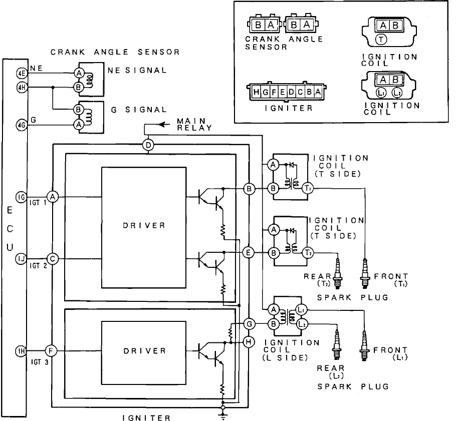
Here's a diagram of how the ignition system work. I believe the 2 CAS is what supply the timing to the ECU. Then the Igniter will look at the TIMING and signal a command for spark. Therefore the coils would ignite and sending the spark down from the wires to the spark plug.
Right now, we have powers to the ignition coils, but 0 SPARK on ALL wires.
Therefore, lets check the igniter for power supply and ground.
And check the 2 CAS when you crank see what voltage you have.
That way we can conclude if the problem is within the ECU itself, the CAS sensors, or the igniter since you are 100% sure that the coils are good.
-AzEKnightz
right now, as I read this diagram. I am leaning towards the CAS or the connection to the CAS being the culprit. Reasoning: Because you've checked that there is power supply to the ignition coils. Which means you have power from the PFC > Igniter > Coil but NOTHING is coming out from the wires (but you've replaced new wires). Therefore I would check on your 2 CAS sensor and the connections to that to make sure it is sending out the signal to the ECU to determine the timing otherwise you will have no spark but power from PFC to the coil.
-AzEKnightz
p.s sorry for the multi-post. I am at my shop dealing with customer's cars while helping you on this =).
-AzEKnightz
p.s sorry for the multi-post. I am at my shop dealing with customer's cars while helping you on this =).
Resistance test the CAS sensors:
Remove sensor and measure resistance across terminals:
0.95 - 1.23K ohms @ 68�F (20�C)
I havent done a CAS backprobe while cranking, therefore I wouldnt know what voltage it would supply the ECU with. Let me dig around to see if I can find any information on that ok?
-AzeKNightz
Remove sensor and measure resistance across terminals:
0.95 - 1.23K ohms @ 68�F (20�C)
I havent done a CAS backprobe while cranking, therefore I wouldnt know what voltage it would supply the ECU with. Let me dig around to see if I can find any information on that ok?
-AzeKNightz
Thread Starter
Joined: Jul 2007
Posts: 1,370
Likes: 13
From: Trois-Rivieres (QC)
OK you really really are big help... I'm pretty sure CAS isn't working properly, I had to fix it on the harness... maybe I did it the wrong way...
I've checked the wires that goes to the connector while key is "ON" and there's no power at all, even before where I fixed the wires. Here's a picture!
Thank you so much!

I've checked the wires that goes to the connector while key is "ON" and there's no power at all, even before where I fixed the wires. Here's a picture!
Thank you so much!
Alright sounds good. By looking at the diagram I've provided, it looks like both "A" wire on the sensor should be getting a signal voltage from the ECU and "B" is the actual reading that will be sent back to the ECU for timing. If you arent getting power to "A", you are most likely disconnected somewhere at the harness. Figure that out and let's see what we've got.
I am glad I could of help. Let me know if you need more information, I will try my best =).
-AzEKnightz
I am glad I could of help. Let me know if you need more information, I will try my best =).
-AzEKnightz