When you click on links to various merchants on this site and make a purchase, this can result in this site earning a commission. Affiliate programs and affiliations include, but are not limited to, the eBay Partner Network.
Where to: Small Vacuum Hoses on lower intake 87TII
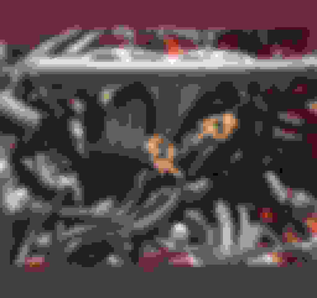
Idk how I misplaced my marking on #1....??? I took the extra time to label everything. #2 what i marked is different then what manual pics say. I hope this pic works. I can take better pics if need be.
#1 is mid lower intake manifold and the original hose is pretty short in the shape of a ? As I�m typing this I�m saying to myself it�s gotta be apparent as soon as I start putting that upper manifold back on.
#2 is where the lower intake almost meets the block, right smack in the middle of two oil injectors.
Anyone know where these go....??? It�s a 1987 Turbo II.
Check out this thread. Already labeled for you. The hose you have labeled #1 is the vacuum reference for your fuel pressure regulator circuit. It will connect directly to your "rats nest" right below it. It goes to the control solenoid that changes pressure at the regulator. The vacuum nipple near the oil injectors, and way down in no-hand-will-fit land, is an air bleed. This hose connects from down by the oil injectors to up on the back side of the upper intake manifold, right next to the throttle body. This bypasses air around the throttle body to the engine. If you don't have this, it messes with the throttle body and idle adjustments because those were designed to work with a certain minimum amount of air bypassing the throttle.
It helps to color code the vacuum nest, so you know what air goes where. Model airplane paint and clear coat work just fine.
Alright so this confuses things more. The back of my upper intake / throttle body doesn�t have 3 nipples. It has 2. Both nipples for mine I have marked. The bigger of the two is for the oil metering splitter and the smaller above it is coming off a herd metal line on the rats nest that attaches to the top of the block.
Im starting to think w all the searching I�ve done to figure **** out that I might have a Series 5 JDM motor in here.
Well the motor I pulled was def a S5, the knock sensor threads were above the spark holes on the rotor housings. I thought maybe just the short block but then in another thread searching... the sensor on the back of the water pump, my plug is black not green.
In the picture you posted of your manifold, you don't have any nipples for the secondary air bleeds, just the primary. This and your oil injector air line should take up those two vacuum nipples.
I�m putting it back the way those were. The lager nipple was hooked up to the oil metering splitter and the smaller went to a hard line in the rats nest on top of the block.
I dont know what air bleeds are.....???
And for now I�m hooking #1 and 2 in the original post to an accessible long hose for each and capping.
Last edited by 85TIIDEVIL; Jun 7, 2020 at 05:28 PM.
I explained air bleeds in the previous postings here... They are just vacuum tubes that bypass air around the throttle body and into the engine. From the diagram for an 87TII, the big nipple on the back of your manifold goes to your oil injectors like you're going to do. The smaller nipple on the UIM connects to the nipple on the LIM down in between the oil injectors. Whether you pipe it through the vacuum nest, or with a straight tube, that's how it is supposed to go. Page 4B-5 of the FSM.
Well I put the upper intake manifold on today. The smaller nipple of the two in the pic I took earlier went to a hard line on the rats nest that if followed does NOT go to the lower nipple btwn the oil injectors and that�s how it was before.
I want to smack the **** out of myself for losing these labels.