
water temp sensor or wiring?


water temp sensor or wiring?
Curious about the water temp sensor on the thermostat housing that goes to the ecu. While logging with my PowerFC I see the temperatures show normal and then will go to 175 followed by -47 or -46. Then the temperature will go back to normal. I am not sure how to check the sensor. Haven't found it in the FSM. Going to check wiring, but while I am working, might check the sensor too.


175 to negative 46?
Replace the sensor if you want, but like I mentioned in the other thread, I'm pretty certain it's the wiring.
Hell, why not run new wires? Not like running 2 new wires is that big of a deal anyways. While you're at it, just get a new connector too. I believe they use something similar to the injectors, so you could sand off the tab on the sensor itself to make a new connector fit if you need.
http://www.diyautotune.com/catalog/f...-ev1-p-48.html
talking head
Joined: Apr 2008
Posts: 2,775
Likes: 15
From: Perth, WA, OZ
sensor are notorious for ungluing the plastic top section after many years
when so the top can twist and provide shorts that have been known to cost engines
( as water temp provides critical function in the fuel algorithm )
however since yours reads cold , this indicates high resistance or broken circuit on delco and denso sender curves
so indicates contacts in the sender may be broken and only in occasional contact
, or the clip holding the harness to the sender may be faulty and the harness loose and breaks contact to the sender with vibration
-continuity fault through sender or wiring
Well, I am just replacing the sensor and the wiring. Trying to figure the wiring out though. I have the new sensor and connector in. Wiring routed into the cab but I am not sure where to go from there. I have the FSM which shows connector b2-32 for the water thermosensor a br/b wire and a g/w wire. It also shows a single wire going into the ecu at pin 2e. I have found pin 2e and the color is correct but where is connector b2-32? I haven't been able to find it. Also, does it matter which wire is connected to the BR/B and which to the G/w? I assumed it was just measuring resistance. Does one wire go to ground and the other to the ECU?
So according to the FSM I should be measuring a small amount of voltage at pin 2E. So I need to know where to connect the other wire and if it matters which goes to pin 2E and which goes to this source of voltage. Looks like the Throttle sensor.
Trending Topics
ECU is n370 pin 2E. B2-23 in the FSM on the Turbo Engine Control Unit. Looking in the Wiring manual pg z-40. The FSM shows the Green/White wire at the thermosensor. The other end appears to go to the throttle sensor, but I am not sure.
the neg number is the default parameter when the ecu see's no signal, so you have have a sensor dropping out or a open in the wiring. you can check the wiring point to point with a ohm or multimeter. make sure you wiggle the wiring to make sure theres no cracks in it while testing it. as for the sensor you can use a ohm meter and hot water to check values at certain temp to make sure its not going in and out.

B2-23 is the plug/connector for the Thermosensor.
Well, I have a new sensor and new wiring. I have wiring into the cab, I just want to know where the other wire from the thermosensor goes. One goes to pin 2E on the ECU, just need the other one.
You could use an existing ground sight for the "other" wire or create a new one.
Verified I am getting voltage to one wire of the old connector for the thermosensor. 5 volts with the key to on, I suppose I can just splice the new connector into the hot wire. I was trying to replace the whole wiring so I know I don't have a problem inline somewhere. Preference would be to find where the voltage is coming from so I can use a new wire.
Run the new wire to pin 2E. The other wire goes to ground. Use the new connector, new wire, new sensor. Do all this, you shouldn't have a problem with it again. Hell, you could even pull that green/white wire out of the harness then to see where the break was. Or maybe it was in the old connector. Who knows.
I can do that. I do have power to pin 2E. So how does this work? If the thermosensor connects to a voltage source at pin 2E and then the other wire goes to ground, what does the thermosensor do? Doesn't make sense to me. I assumed the voltage was coming from another source, being modified as it passed through the thermosensor, and then fed that voltage to the ecu. Does anyone understand what actually happens. According to the FSM the voltage at pin 2E changes based on temperature so I figured this was the voltage fed from the sensor.
Curious about the water temp sensor on the thermostat housing that goes to the ecu. While logging with my PowerFC I see the temperatures show normal and then will go to 175 followed by -47 or -46. Then the temperature will go back to normal. I am not sure how to check the sensor. Haven't found it in the FSM. Going to check wiring, but while I am working, might check the sensor too.
The water thermosensor is a thermistor. The resistance changes as temperature increases. The reference voltage passes through the thermistor and the voltage at FD pin 3E will go down as the engine warms up.

You can check the sensor voltage with the etc. --> sensor check screen.
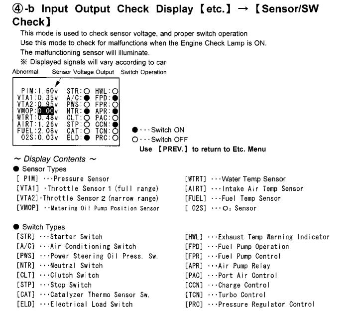
If the WTRT value changes rapidly and drastically, I would suspect a failing electrical connection like a trashed connector causing an intermittent problem. The FC sensor uses Bosch EV1 injector connector with an offset tab. It's the same connector as the s4 BAC valve and the 88 model injectors.
You can de-pin the factory connector and install an EV1 connector on the original pins, or a salvaged connector from a junk harness. If you have an EV1 connector just file down the tab at the bottom and it will work. The thermosensor also can read inaccurately when it gets old. You can get another one from Mazdatrix http://www.mazdatrix.com/86-92Electrical-Engine.htm .
Last edited by arghx; Jan 5, 2011 at 07:06 PM. Reason: image
The car is an S5. I have a AP Engineering PowerFC and the adapter is very nearly the same as the Banzai one. Looking at the FSM for the S5 I should be checking voltage at pin 2E. Pin 2E has 5 volts with the ignition on even without the Thermosensor hooked up. That is why I am confused about connecting one wire to pin 2E and the other to ground. I have a datalogit and that is my only way of logging. Supposed to have ~2.4 volts at 68F and .3-1.0 hot by S5 FSM. Still factory wiring.
From what I gathered, it's an S5 with the power FC. Not sure whether it matters or not on the patch harness or what, but it should still be pin 2E if going by the stock harness identification.
And I think he already got the new connector, I recommended he get one in post 3. I still highly doubt it's the sensor. If they fail, it's usually a complete failure. Open or short, it should stay that way. When wiring goes bad, it's got a much higher chance of going gremlin on you.
I think he's on the right track. So long as he can properly solder the connection to pin 2E, he's solid.
The car is an S5. I have a AP Engineering PowerFC and the adapter is very nearly the same as the Banzai one. Looking at the FSM for the S5 I should be checking voltage at pin 2E. Pin 2E has 5 volts with the ignition on even without the Thermosensor hooked up. That is why I am confused about connecting one wire to pin 2E and the other to ground. I have a datalogit and that is my only way of logging. Supposed to have ~2.4 volts at 68F and .3-1.0 hot by S5 FSM. Still factory wiring.
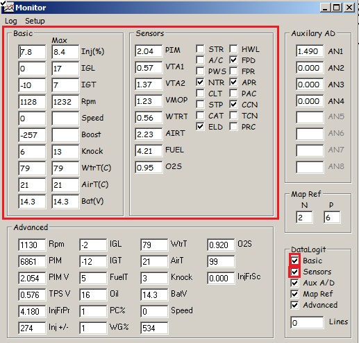
"Basic" is the same screen you would have if you were in the monitor window on a Commander. "Sensors" is the same data as on the sensor screen for the Commander. So check the WtrT voltage under sensors and check the WtrT temperature in Celcius. What do you see? Can you take a screenshot? Or can you log data showing the problem and then post the log file?
Don't make this more complicated than it has to be. Most likely you can leave the wires alone. You either have a bad sensor, a bad connector, or an improper diagnosis. Even if the connector is bad, you don't have to cut anything. Those connectors can easily be de-pinned or broken with some cutters. Then you can insert the intact pins into the new connector. I have replaced connectors like that before. My BAC valve connector is a replacement Bosch EV1 injector connector that I installed by-depinning the messed up original connector.
So when I ran the new wires I wasn't paying attention to which lead in the sensor was to the green/white wire. Does it matter on the new ones? It won't be hard to backtrack, I just want to make sure before I solder the new wire and attach the ground point.
Thanks to everyone on this thread. I replaced the sensor, connector and wiring to the ecu. The sensor was cheap enough I just went ahead and replaced it. I drove just over 200 miles in the car yesterday without a single problem. Thanks again.

Thread
Thread Starter
Forum
Replies
Last Post
sherff
Adaptronic Engine Mgmt - AUS
9
Feb 24, 2019 12:09 PM
immanuel__7
2nd Generation Specific (1986-1992)
89
Sep 5, 2015 10:23 AM
befarrer
Microtech
3
Aug 22, 2015 05:52 PM